
Abstract
Planning of strip layout is one of the important activities of progressive die design in sheet metal industries. The optimum and economical die design mainly depends on the design of strip layout. Many methodologies are used to determine optimum strip layout, but there is no literature available for strip-layout simulation. Petri net is one of the most suitable methodologies for simulation of strip layout. In this article, two research contributions are described (1) to apply the visual Petri net to simulate the sequential workstations in the strip layout of part and (2) to integrate the parametric design of strip layout and simulation using Petri-net technique. To demonstrate the present research contribution, two case studies are also discussed.
Introduction
The planning of strip layout is the first activity of die design process. The decision made during strip-layout planning plays a vital role not only in the design of progressive die but also economical production of defect-free sheet metal parts. The progressive die design is a complex, time-consuming, error-prone, and highly experience-based activity. 1 The degree of complexity of progressive die design increases with the increase in number of die stations. The process of strip layout has many stages, including design, process planning, optimization, simulation, and verification. Many researchers have applied efforts to develop computer-aided systems for strip-layout planning of progressive die. For example, Ngoi and Chua 2 applied the knowledge-based approach to describe the strip-layout features, design, and planning. Lin et al. 1 studied the application of Petri net (PN) in strip-layout planning in two dimensions (2D) including shearing operations. This model includes 5 shearing stations, 16 places, and 8 transitions. Later on Lin and Horng 3 extended their work to include shearing operations in three dimensions (3D). The model includes 12 stations, 25 places, and 17 transitions. Lin and colleagues1,3 used the discrete technique in their work. Chu et al. 4 used graph method for strip-layout design of progressive die. This approach incorporates rules and heuristics used by human process planning experts and synthesizes the reasoning process using graph theoretic algorithms. Chang et al. 5 applied genetic algorithm (GA) technique for design of strip layout. Kumar and colleagues6,7 developed an intelligent system to design the strip layout for progressive die parametrically.
The PN methodology can be used in modeling, simulation, and performance analysis of strip-layout planning.
In this study, two research contributions are described. A visual PN code called “HPSim” is constructed to simulate the strip-layout design of the designed workstations. This strip-layout system has used the continuous technique inside PN. The second contribution is the development of an integrated system to integrate the parametric strip-layout design as prepared by Kumar and colleagues6,7 and the PN simulation module. This integrated system is built on the platform of AutoCAD software. Two case studies are taken from the work of Kumar and colleagues6,7 to demonstrate the present contributions.
Strip layout
It involves laying out the material strip of sheet metal to be passed through the eccentric press in order to produce stamping parts exactly as per the part design. It also determines the number of working and idle workstations, punched, blanked, bent, or formed features at each workstation and the operation sequence at each workstation of progressive die. The productivity, accuracy, cost, and quality of progressive die as well as sheet metal parts that will be produced depend to large extent on strip-layout planning. Therefore, the design of strip layout is considered as one of the important activities of progressive die design. The design of strip layout is a part of process planning of die design. The process planning of progressive die design involves the following three steps:
Unfolding the 3D sheet metal stamping part into a flat pattern;
Nesting of parts to maximize the strip utilization;
Deciding the number of stations on progressive die and sequence of operations on each workstation. This is termed as strip layout.
On the basis of strip layout, the progressive die is to be designed and manufactured. Progressive die is an assembled unit of various components such as die block, punches (piercing, blanking, etc.), pilots, pitch punches, punch plate, strippers, guide plates, die-set, and fasteners.
Nowadays, commercial computer-aided design (CAD) systems are being used worldwide for part modeling, unfolding, and nesting. But design of strip layout is still done manually by experienced die designers. Only few studies have been reported in the literature for automation of design of strip layout. 7 In sheet metal industries, it is still believed that design of strip layout is an art rather than a science. Recent advances in CAD and artificial intelligence (AI) have given opportunity to the researchers to develop automated systems with built-in intelligence to ease complexity in progressive die design including strip layout.
PNs
PNs are a mathematical and graphical modeling tool applicable to many systems. It is first suggested by Carl Petri in 1962 during his PhD work. It was used for modeling, simulating, and analyzing the discrete event dynamic systems. Now, it is an important tool for studying and describing information processing systems that are characterized as being asynchronous, concurrent, parallel, distributed, nondeterministic, and/or stochastic. A PN or place/transition net N is a four-tuple (P, T, F,W) where P and T are finite, non-empty sets, and disjoint sets. P is a set of places, and T is a set of transitions, elements belonging. The basic concepts of PN and the advantages of using PN in the construction of system modeling and simulation are described in detail by Lin et al., 1 Lin and Chua, 3 Peterson, 8 and Li and colleagues.9,10 For the details of PNs, the reader is referred to the study by Li and Zhou. 11 PNs have found their extensive application in, control, 11 modeling, 12 particularly deadlock control,13–16 scheduling,12,15,17–23 and performance analysis18,19 of resource allocation systems, particularly flexible manufacturing systems.24–27 Note that when PNs are used to model a resource allocation system, they are two modeling paradigms: resource-oriented Petri nets (ROPNs)19–22 and process-oriented Petri nets (POPNs). 12 The former can usually provide a convenient and compact model compared with the latter. However, the POPNs are used by more researchers than ROPNs.28–32
Planning of shearing-cut strip layout using Petri-net approach
The bottom-up synthesis method of PN is more suitable for planning the workstations of progressive die for shearing operations. The reason is that for the bottom-up method construction, each subsystem (i.e. single punching die workstation) is typical and actual solid equipment in the real world. Thus, corresponding relationship of each subsystem merging with the entire system will be more direct.
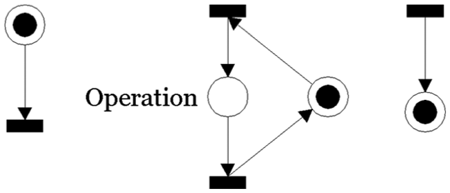
Steps of the PN graph construction for shearing-cut strip layout for progressive die workstation are follows: the state of this level (subsystem) is the actual single punching station equipment in an actual factory (single die’s workstation) as shown in Figure 1. Analysis of the movement operation sequence and changes of conditions of these single punching stations can establish the PN graph of these stations. In the primary PN graph, all places are state places denoting the working conditions. The flow of tokens represents changes of the punching state of the working of a die workstation.

Single punching station’s working process.
The upper-level control center mainly connects the operation of all working stations inside the lower level and monitors working conditions of various working stations. Therefore, the reason why the primary PN of this control center can be established is mainly based on the functions that can be executed by the subsystems and the analysis of their output and input parameters. The construction of the primary PN of this control center mainly relies on the function that can be executed by subsystems and the analysis of the input and output conditions. The primary PN graph of the control center is also the basis of reference base of the system’s control logic.
The so-called communication place denotes the basis of communication with the upper and lower levels. These communication places appear at all die workstations and the PN graph of the upper level in pairs. These pairs represent response of the conditions of the various levels in the system. Tokens of the communication places can flow between the upper and lower levels in the PN graph to denote the condition of message communication during the workstation of the shearing-cut progressive die.
The so-called compensation for upper and lower dies offset displacement exist for the following reason. During the working process of tile shearing-cut progressive die, the imbalance between the torque on both sides along the upper and lower tiles causes an offset displacement. The communication of compensation message serves its command delivery and response of condition to let designers change the initial design according to the scale of the upper and lower die offset displacement. The communication of a compensation message can deliver its orders and report the states. Designers can change the initial design based on the amount of the upper and lower dies’ displacement to avoid unbalanced moment on the right and the left sides during the working process of the shearing-cut progressive dies.
Case Studies
Case study 1
Description of PN in a strip layout
Figure 2 shows the sheet metal part and Figure 3 depicts the strip layout automatically generated by the intelligent system as proposed by Kumar and Singh. 7
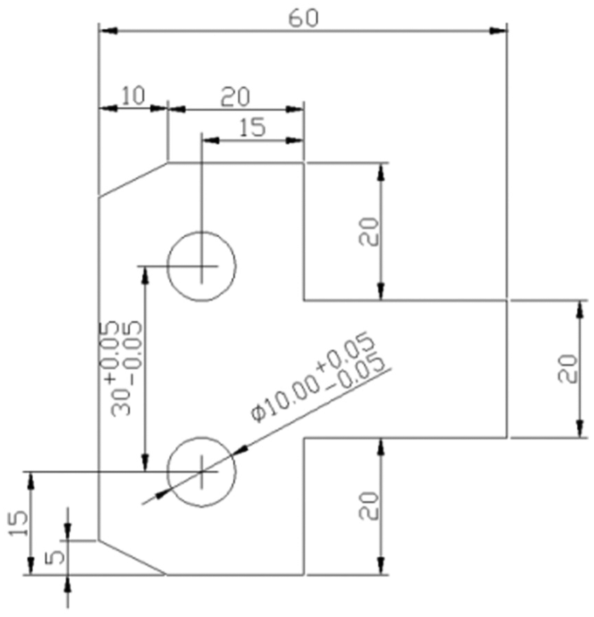
Sheet metal part (all dimensions are in mm). 6

Figure 4 shows the PN graph of the places representation. There are five places in Figure 4(a) and two transitions in Figure 4(b). Describing the working actions of a punch press is shown in Figure 4(b). It should be noted that a punch press machine means a die workstation at this time. When a punch press machine is idle, p1 sends an order. Therefore, p1 is also called a communication place. When the punch press machine is idle and a message arrives (p2 and p4 have tokens), the punch press machine begins to punch the workpiece (st means that t1 is fired). At this moment, tokens start to shift. After the tokens of p1, p2, and p4 are shifted out, it means that the punch press machine is not idle. When a token is shifted to p3, it means that the punch press machine is processing a workpiece, as shown in Figure 4(c). At last, t2 is fired as shown in Figure 4(d), which also signifies that the punch press machine has finished the punch work.

PN of the places representation: (a) representation of places, (b) initial working state of a single punching station, (c) PN graph after the firing of t1, and (d) PN graph after the firing of t2.
At this time, tokens are shifted. The token of p3 is shifted out and the tokens are shifted to places p2, p4, and p5. Place p5 indicates the completion of punch work while p4 reports to the system of initial state that indicates the punch press machine is idle at this time.
When p1 sends an order (input of information concerning workpiece to be punched), another new cycle is initiated by the firing of various places and transitions. After the primary PN graphs of sub-levels (such as mentioned above, the working process of a simple punch press machine) are established, the bottom-up synthesis method introduced earlier is applied to expand the working conditions of various workstations into a complete structural graph of the shearing-cut progressive die working system.
In this example, a shearing-cut progressive die working system containing five workstations is considered. At this time, the workstation likes the major construction of a simple punch press work, where the first workstation does the guiding hole punching and the other workstations are for punching and blanking. After passing through five workstations, the workpiece goes out from the last station and the shearing-cut progressive die working is completed; Figure 5 shows the sequence of continuous PN technique which represents the strip-layout working.
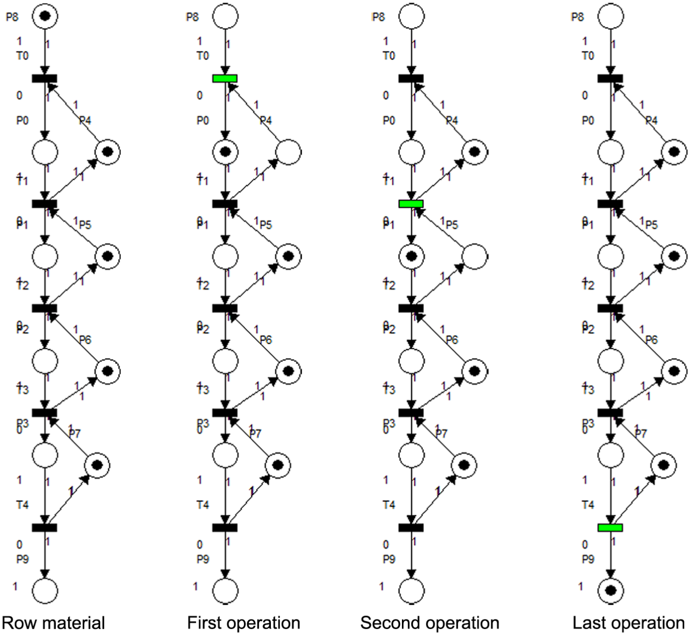
The visual PN for the continuous technique for strip layout (case study 1).
Case study 2
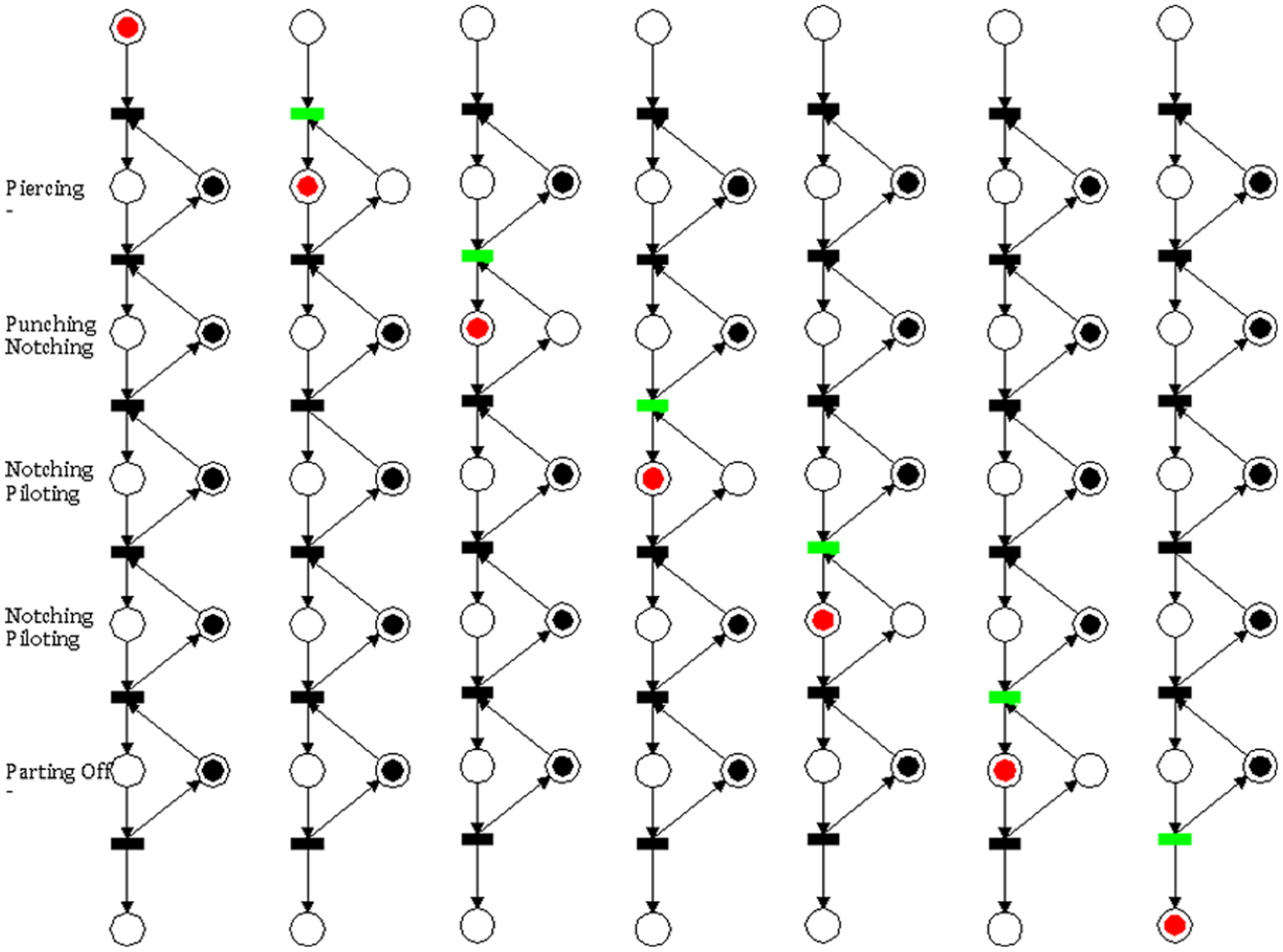
Figure 7 shows the strip layout for a typical sheet metal part shown in Figure 6 which taken from the work of Kumar. 6 The PN graph of this strip layout is illustrated in Figure 8.

Sheet metal part. 6

Strip layout of a typical sheet metal part shown in Figure 6. 6

The visual PN for the discrete technique for strip layout.
PetriCAD for strip layout
AutoCAD customization and programming have wide applications in many engineering applications. The power of AutoCAD comes from its 2D drafting module. The visual Petri-net program represents the network also in 2D drafting. Also the Petri-net application for strip-layout simulation uses small part of the Petri-net possibilities. Kumar 6 has developed a computer-aided system for automatic strip-layout design for progressive dies. The system is constructed using AutoCAD software. Adding the PN as an extra module to the automated strip layout will certainly enhance the capability of the system. The next section discusses about AutoCAD programming and customization to be a Petri-net module for strip layout.
The system description
The proposed system integrates intelligent system for strip-layout design (ISSLD) module developed by Kumar 6 and the new module which called “PetriCAD” constructed in this study. The ISSLD module generates strip layout automatically in the drawing editor of AutoCAD software. The data input for ISSLD module is the 2D part drawing. The module also stores its output data such as number of stations, detail of operations performed at each station, punch number, punch dimension in a data file, and 2D drawing of strip layout in a drawing file.
The developed PetriCAD module receives its input from the output data file of ISSLD module. The module is connected with script file which include a number of circles which denote “places,” lines and arrows which denote “transition,” closed donuts which denote “tokens,” and text to be inserted beside each place with the name of operation. The script file is connected with AutoLISP, which receive the data file and reconstruct the number of station on the AutoCAD screen using a simple loop. The AutoLISP includes some of the PN rules which direct serve in the strip-layout problem and connected with the AutoCAD script file to draw the PN graph as in Figure 9.
The Petri net items in the PetriCAD module.
The script file includes a number of layers which are controlled by the code. The token represents as AutoCAD donut and put in each circle, which represent place. The token is placed on a number of layers, some of them are hidden and some appear as layers. As the script starts working to represent the PN for strip layout as programmed by AutoLISP, the movement of token will represent as layer hidden from the departure place and layer appear in the arrival place. In the same way, the transition will change its color from black to green, to represent the movement from station to other. The whole system is represented in AutoCAD screen as shown in Figure 10 for discrete simulation and Figure 11 for continuous simulation.
The discrete simulation steps for case study 2 based on PetriCAD module.

The continuous simulation steps for case study 2 based on PetriCAD module.
Conclusion
Continuous simulation for the strip layout using PN is presented in this article. Continuous technique is most suitable and logical to simulate this kind of problems. The AutoCAD programming can be used to visualize the PN simulation for the strip layout. The suggested PN model in this study is quite simple and certainly it is an effective technique for more sophisticated strip-layout designs.
Footnotes
Academic Editor: ZhiWu Li
Declaration of conflicting interests
The author(s) declared no potential conflicts of interest with respect to the research, authorship, and/or publication of this article.
Funding
The author(s) disclosed receipt of the following financial support for the research, authorship, and/or publication of this article: This work was funded by the National Plan for Science, Technology and Innovation (MAARIFAH), King Abdulaziz City for Science and Technology, Kingdom of Saudi Arabia (Award Number 12-INF2816-02).