
Abstract
The purpose of this study was to use a hybrid frequency response function–based substructuring synthesis method to predict the structure-borne noise of a vehicle frame resulting due to excitation by the engine and to develop a noise reduction method for optimizing the subframe model. The finite element models of the subframe were first verified by comparing their natural frequencies and frequency response functions with those of the real subframe models. Several substructures were then defined and the vehicle interior noises were predicted using the hybrid frequency response function–based substructuring synthesis method. Based on the prediction results, different target frequency ranges were selected, and different methods for optimizing the subframe model to reduce noise were investigated within the selected frequency ranges. Finally, the subframe modes within the selected frequency ranges were analyzed and new noise reduction models were developed by modifying the thickness of parts of the original subframe.
Keywords
Introduction
Excessive interior noise in vehicles is annoying, fatiguing, and stressful to both drivers and passengers, and the large number of sources of the noise makes reduction difficult. The noise types include turbulent boundary layer noise, tire/road noise, and motive power plant noise.1,2 A theoretical investigation of vehicle interior noise requires an understanding of the transfer functions between the reference noise sources and the response signals. Indeed, various methods for deriving the transfer functions of complicated systems have been developed over time.
Traditional transfer path analysis (TPA) is a very well-known method for deriving the transfer functions. However, it is difficult to derive the transfer functions for impact hammers in complicated systems such as motor cars and trains. 3 Moreover, the use of traditional TPA to determine the transfer functions and source quantities such as the operational forces and volume velocities is time-consuming. To overcome these challenges, new methods such as operational TPA have been suggested more recently. 4
Operational transfer path analysis (OTPA) is a method for directly deriving the transfer function from operational data. 5 The method was proposed by T Sakai and A Sakamoto 6 for the contribution analysis of vehicle interior noise. The usefulness of the method was verified by the degree of similarity between its results and those of actual interior noise measurements and interior noise synthesis using the operation transfer function within a frequency of 2000 Hz. The method is thus effective for analyzing the causes of interior noise based on the transfer functions. However, the method cannot be used to determine the effects of design changes because it is experiment based rather than analytical. Conversely, an analytical finite element method is useful for examining the effects of design changes. Such a method can be used to determine the dynamic characteristics of various models obtained by computational calculation. 7 However, substantial time and effort are required to develop full-scale finite element models of a vehicle owing to the complex shape.
In view of the forgoing, a frequency response function (FRF)-based substructuring (FBS) method was proposed for the analysis of complicated vehicle models. 8 The FBS method is used to predict the dynamic behavior of a structure based on the dynamic behavior of the constituting substructures. The FRFs of the overall structure is determined from those of the substructures. For instance, Ochsner and Bernhard 9 used the method to analyze the transmission of structure-borne noise from a vehicle tire spindle, through the suspension, and into the passenger compartment. The FBS method has been used to predict the dynamic behavior of a coupled system using the free-interface FRFs of the uncoupled components. 10 In this previous study, the method was used together with the modal synthesis technique to analyze vehicle finite element data. The error due to modal truncation was particularly taken into consideration.
Hybrid FBS, which combines the finite element method with experimental modal testing, has also been proposed for the prediction of interior noise in complex structures with high modal densities. 11 When FBS is used to investigate the dynamic characteristics of a complex structure, the components of the complete structure are divided into simple structures and complex structures for analytical and experimental analyses, respectively. 12 This procedure saves time and effort by optimally exploiting the advantages of the experimental investigation of the complexly shaped parts of the system. Contribution analysis of system changes may also be conducted using analytical structural models. However, the application of this method to a complex system requires the analytical models to be reliable alternatives of the real models. It is therefore necessary to compare the dynamic characteristics such as the natural frequencies, FRFs, and mode shapes of the analytical and real models.13,14 With regard to hybrid FBS, DH Lee et al. 15 used it to perform a sensitivity analysis of the engine mount system of a passenger vehicle. They applied finite element analysis to the engine mount structures, while the trimmed body including the cabin cavity was experimentally investigated. The obtained interior noise results confirmed the efficiency and accuracy of the hybrid FBS method. However, the researcher did not suggest practical noise mitigation measures through the use of subframe models.
In this study, hybrid FBS was used to predict the structure-borne noise of a vehicle frame due to excitation of the vehicle engine and to develop a noise reduction method for optimizing the subframe model. A finite element model was first developed from the real subframe model and was verified by comparing its natural frequency and FRF with those of the real subframe model. The substructures were then defined and the vehicle noise was predicted by the hybrid FBS method. Target frequency ranges were selected based on the prediction results and used to investigate different methods for optimizing the subframe model for noise reduction. Finally, the subframe modes within the selected target frequency ranges were visualized and used to generate new models for noise reduction by modifying the thickness of the original subframe.
Hybrid FBS
The major underlying ideas of FBS are compatibility and equilibrium. The conditions of compatibility and equilibrium of an assembly are defined based on the connection points of each substructure of the assembly.
Let us consider an assembly comprising n substructures, as shown in Figure 1. Let fi be the force applied to each substructure, and xi the corresponding displacement. Each substructure is rigidly connected at a point. If the coordinate A of the assembly and coordinate n of each substructure are associated, the displacement and force applied to the assembly would, respectively, satisfy the following equations

where x and f denote the displacement and force, respectively, and the subscripts A and 1, 2, …, n are the coordinates of the assembly and individual substructures, respectively. Equation (1) can be expressed in matrix form as follows

where x and f are the same as in equation (1). Equation (1) can be expressed in matrix form as follows


Substructures and the full assembly.
Based on the characteristics of the substructure

This is a representation of the compatibility and equilibrium, as mentioned earlier.
The concept of FBS was developed to satisfy the requirements of accuracy and efficiency. By accuracy, it is meant that the predicted characteristics of the assembly should not be sensitive to errors in the analytical calculation, while efficiency implies that the prediction should require a short time and little effort. In this context, the receptance coupling (RC) method is typically used for substructuring.16,17
The application of the RC method to the receptance matrix presented as equation (3) gives the following

where the subscripts m and i denote the combined and uncombined coordinates, respectively; the subscripts j and n denote the connection and non-connection points, respectively; the matrixes

Limitations of the RC method.
However, in the generalized receptance coupling (GRC) method, all the substructures form a substructuring system, as shown in Figure 3.18,19 The receptance matrix of the substructure is thus expressed as follows


Substructure and assembly systems.
The relationship between the reference and the response points can be expressed as follows

In equations (6) and (7), the subscripts a and n denote the coordinates of the assembly and a substructure, respectively; and the subscripts b, c, and j denote the connecting points. The connection coordinates

The non-connection coordinates do not change with the connection process, as expressed by the following

Based on equation (8), equation (6) can be expressed as follows

By introducing equations (8) and (9) into equation (10), we have

Assuming
Moreover, equation (13) can be obtained from equation (8)

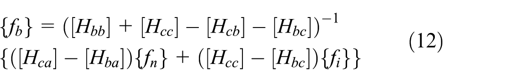
By substituting equations (12) and (13) into equation (6), the following can, respectively, be derived from equations (14)–(16)

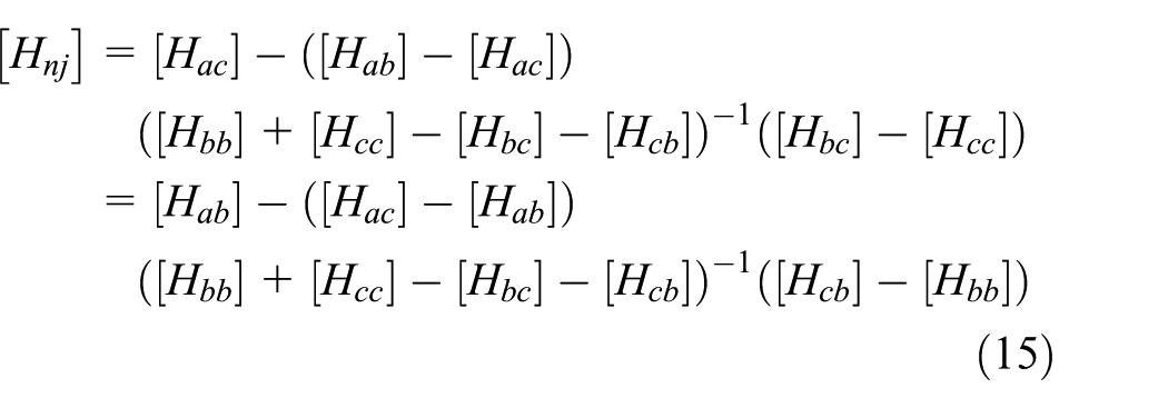
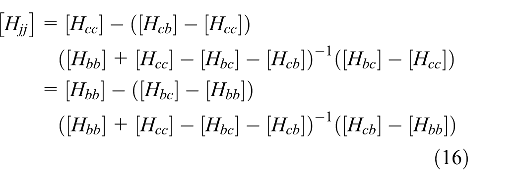
Equations (14)–(16) can be expressed as follows

Equation (17) is the GRC method equation, which can be seen to be similar to that of the RC method. It is obtained by physical generalization for practical application. Moreover, the GRC method can be applied to an assembly that connects several substructures, as well as one that forms a single connection between two points.
Application to vehicle interior noise
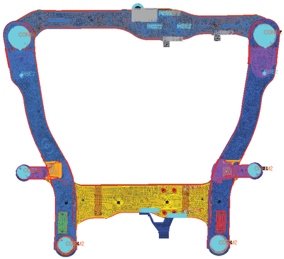
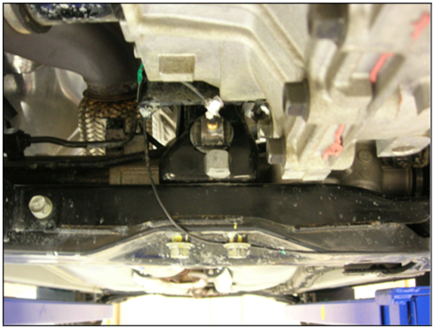
In this study, the hybrid FBS synthesis method was used to analyze the interior noise of a vehicle in which the motive power plant was considered as the main noise source. The transfer paths of the vibrations generated by the engine mount were thus analyzed separately from the vehicle structures. The vibrations generated by the engine were initially transmitted to the subframe through two roll mounts, as shown in Figure 4, and then to the vehicle body through six connection points between the subframe and the vehicle body, as shown in Figure 5. The vibration of the vehicle body caused structure-borne noise in the vehicle cabin. The transfer paths between the two input and six response points on the subframe were considered as substructure A. In addition, the six input and one response points of the vehicle body were defined as substructure B. The response point of the vehicle body was set at the position of the driver’s ear. After the substructuring, FBS was implemented using the GRC method.

Substructure A: subframe.

Substructure B: trimmed car body and response points.
The dynamic characteristics of the finite element and real models of the subframe were compared to verify the finite element model. For this purpose, a modal test was conducted on a real 21-kg subframe model, as shown in Figure 6. Eight accelerometers were installed at the input and response points, and two input points on the front and rear roll mounts were exited with an impact hammer. The response accelerations at the six output points were then measured in the x, y, and z directions. The actual frequency and mode shapes of the model were determined from the results.

Front subframe modal test.
The finite element analysis of the subframe was conducted using NASTRAN in the MSC software (see Figure 7). The element size was first optimized because a too small element could significantly increase the calculation time, while a large element would limit the representation of the physical shape of the real model. The values of the dynamic characteristics were observed to converge with decreasing element size, as shown in Figure 8. We could therefore determine the optimal element size by investigating the convergence of the dynamic characteristics. To do this, we analyzed the natural frequency of the finite element model of a part of the subframe using various element sizes, namely, 1, 2, 4, and 8 mm, respectively. The considered subframe part is shown in Figure 9. As shown in Figure 10, the 1-, 2-, and 4-mm elements produced the same frequency characteristics up to 2200 Hz. The natural frequencies for different parts using 2- and 4-mm elements are compared in Figure 11. Based on these results, a 4-mm element was concluded to be optimal for the subframe model used in this study.
Front subframe FE model.

Comparison of the dynamic characteristics for different element sizes.

Test component for optimization of the element size.
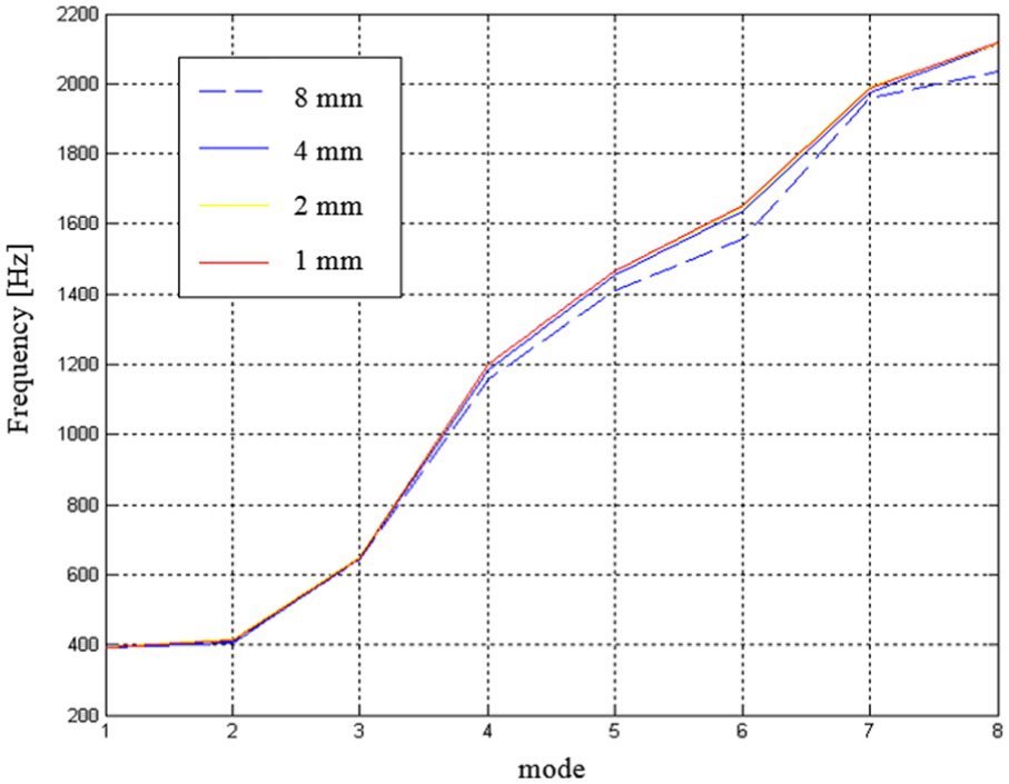
Relationship between the mesh size and natural frequency.
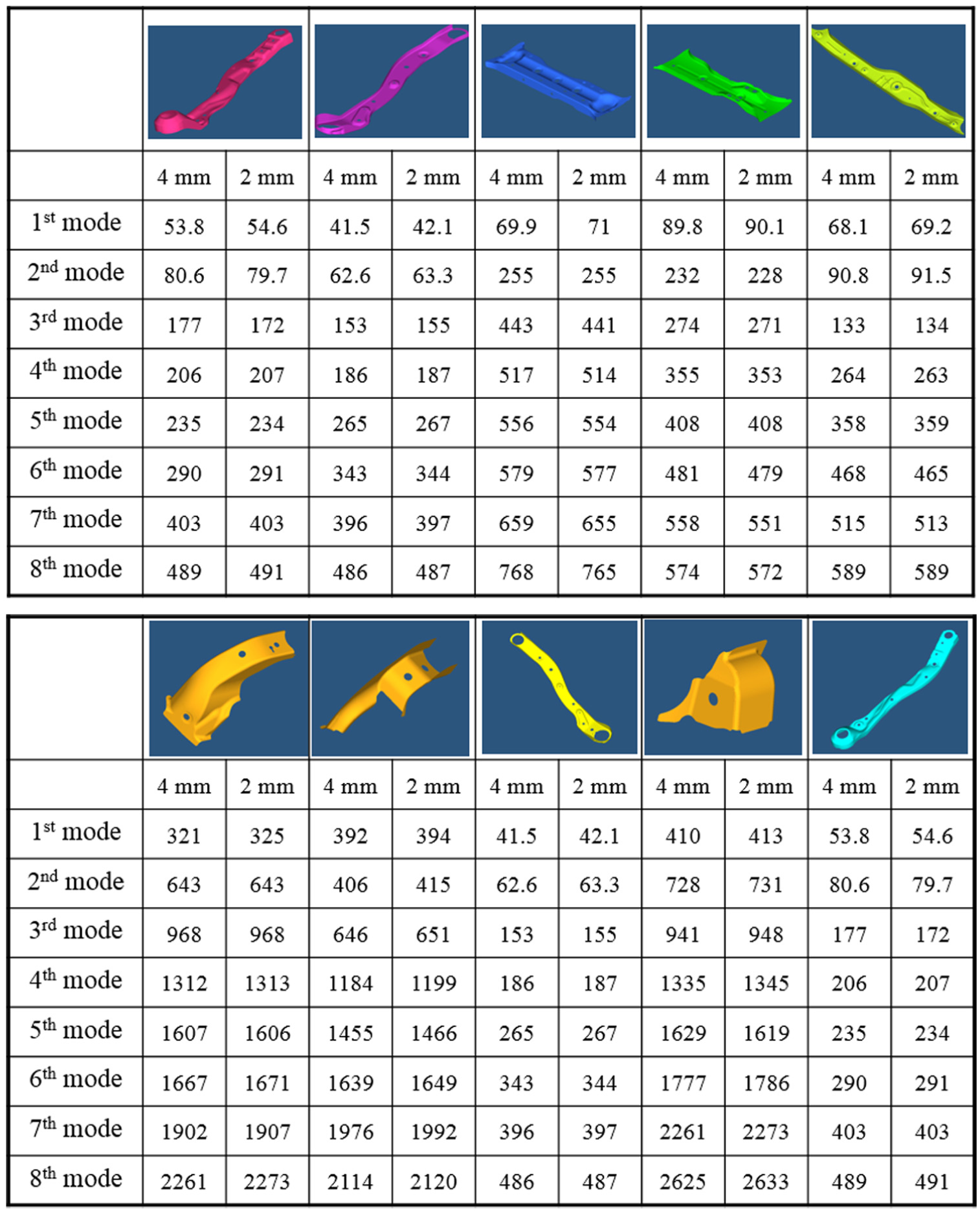
Convergence of the natural frequencies of the components.
After optimization of the element size, the dynamic characteristics of the finite element model of the subframe were determined by finite element analysis, and the results were compared with those of the real model. The differences between the characteristics of the two models were within 5% for frequencies of up to 500 Hz (see Table 1). The characteristics of the vehicle frame were also determined by modal testing.
Comparison of the natural frequencies of the test model and FE model.
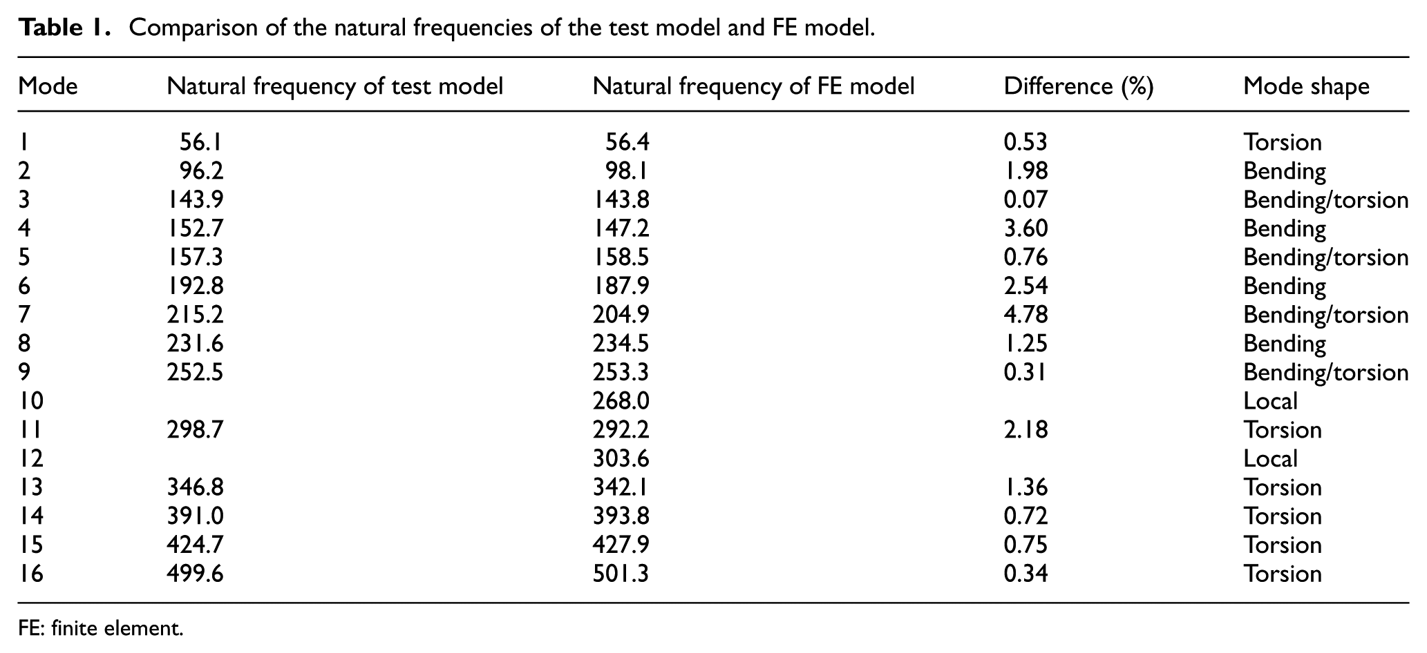
FE: finite element.
In this study, the noise generated by a vehicle substructure was predicted using the FRF, as illustrated in Figure 12. The employed FBS method may be implemented using experimental or analytical data depending on the characteristics of the substructures. The FRFs of substructure A were determined in this study by finite element analysis. In the case of substructure B, the noise transfer functions between the connection point and the position of the passenger’s ear were determined experimentally using an impact hammer. In addition, the dynamic stiffness of the connection bushing elements was determined by measurement and interpolation, as shown in Figure 13. The FRFs of the real and finite element models were compared, as shown in Figure 14. Consistency can be observed between the two up to a frequency of 300 Hz. However, there are many peaks in the curve of the finite element model beyond 500 Hz. This is attributed to the difficulty of detecting the local and torsion modes of a finite element model by modal testing of a real model. The obtained results confirm the reliability of the finite element model up to a frequency of 300 Hz.
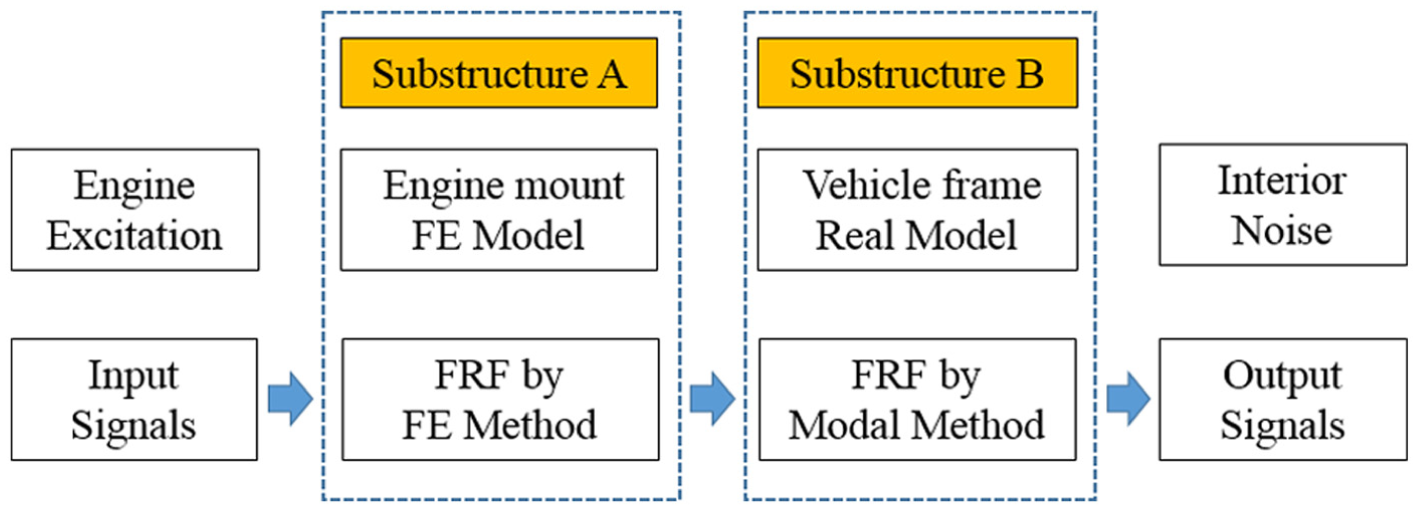
Interior noise prediction using the substructuring method.
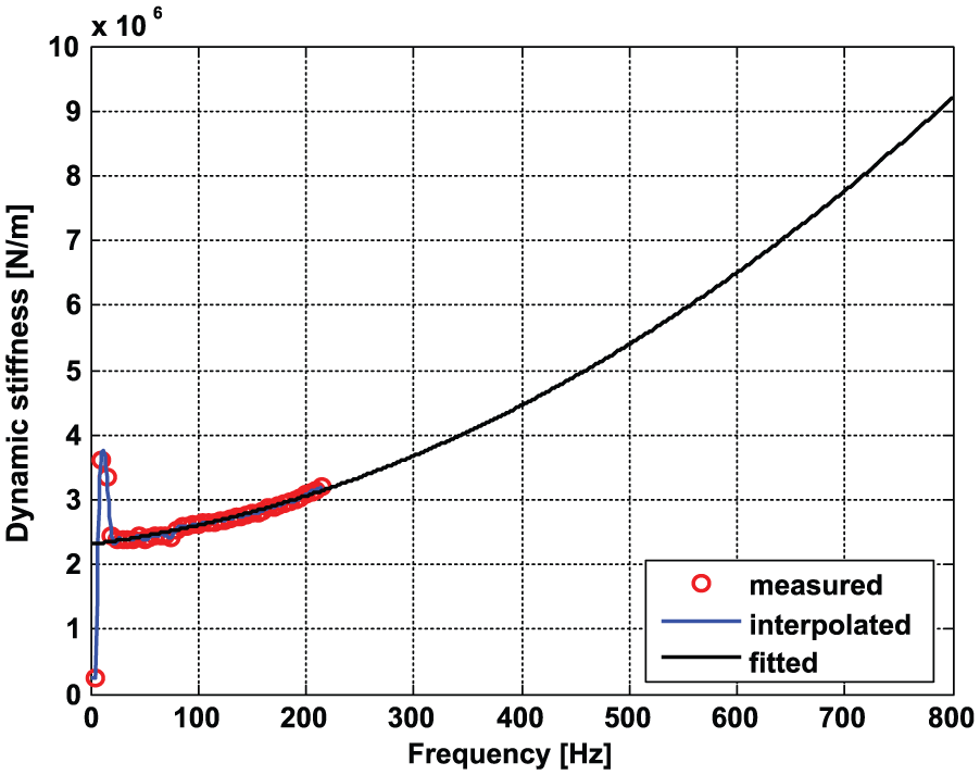
Dynamic stiffness of the bushing elements at the connection points.

Front subframe frequency response function.
The purpose of this study was to estimate the FRF of a complex structure through experimental and theoretical approaches. However, owing to the impossibility of accurately predicting the FRF of a real vehicle, the reliability of the employed method was assessed based on the overall trend of the prediction results. After validation of the finite element model, we obtained the FRF by substructuring. Figure 15 compares the substructure FRFs of the finite element model and actual model. General consistency can be observed. The interior noise was predicted by summation of the transfer functions of the different excitation sources. The results are shown in Figure 16.

Comparison of the measured frequency response functions with those determined by FBS: (a) X direction. (b) Y direction, and (c) Z direction.
Vehicle noise predicted using the FE model.
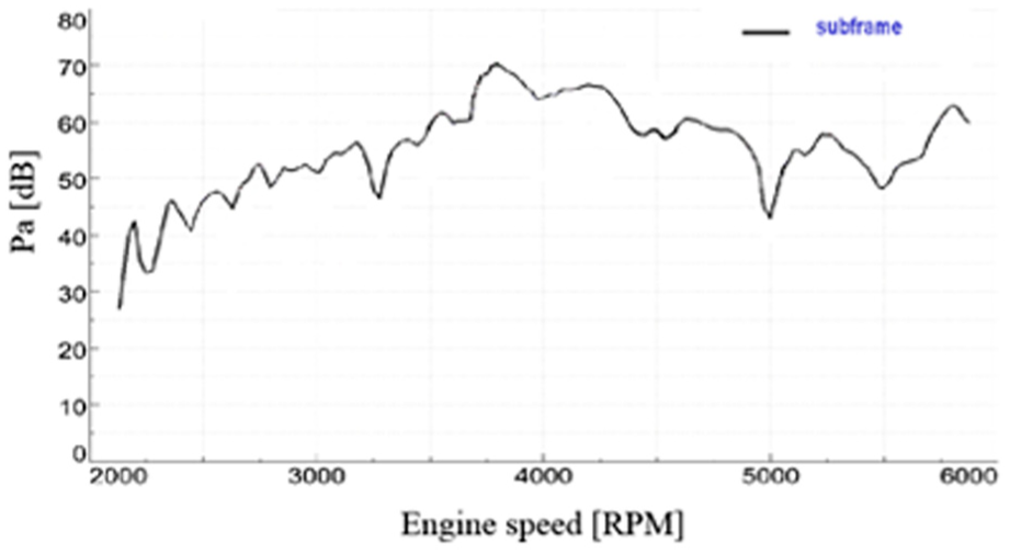
The engine of the vehicle considered in this study was supported by four mounts, namely, a rear roll mount, engine mount, transmission mount, and front roll mount (see Figure 17). Two of the mounts were connected to the vehicle body, as shown in Figure 18, while the other two were connected to the subframe, as shown in Figure 19. The connection points were selected as the transfer paths, which were used to perform a contribution analysis. The analysis results shown in Figure 20 suggest that the noise was generated within a frequency range of 70–110 Hz. The transfer path of the rear roll mount can also be observed to have made the largest contribution.

Locations of the four engine mounts.
Location of the rear roll mount.

Location of the front roll mount.
Results of the noise contribution analysis: (a) engine mount, (b) rear roll mount, (c) transmission mount, and (d) front roll mount.
Possible noise mitigation measures were also investigated by analyzing the mode shapes of the subframe model using the finite element models shown in Figure 21. It was observed that the bending modes of each beam were dominant in the first, second, and third modes. We therefore recommend the reinforcement of the bending modes to reduce vibration excitation by the engine.
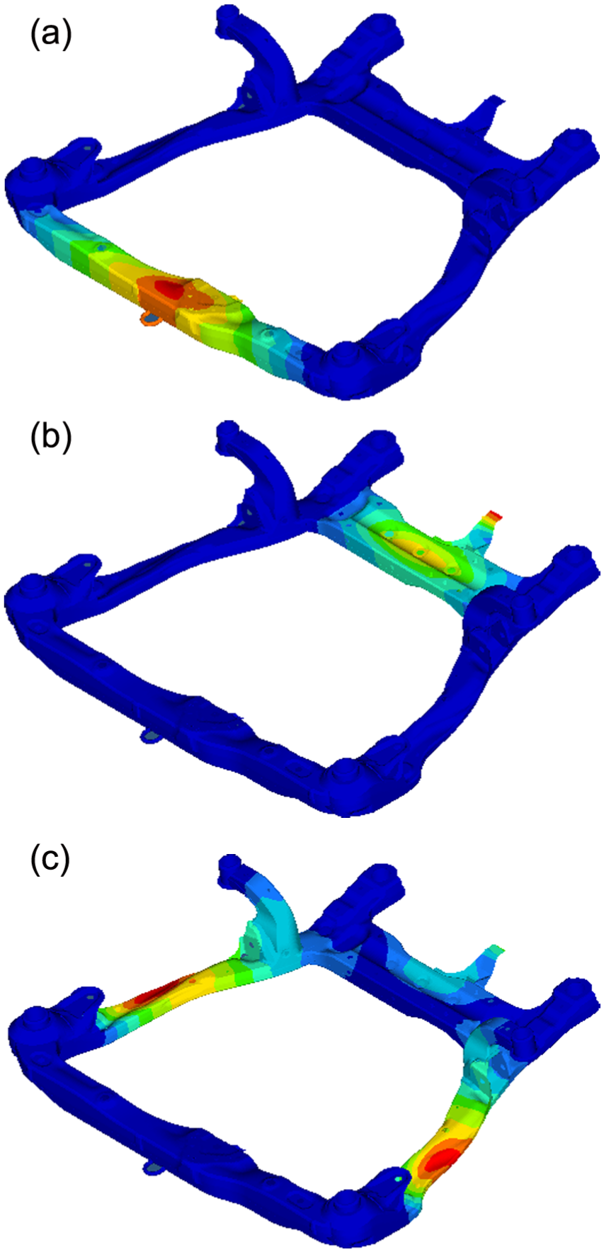
Mode shapes of the finite element model for rigid connection: (a) first mode shape, (b) second mode shape, and (c) third mode shape.
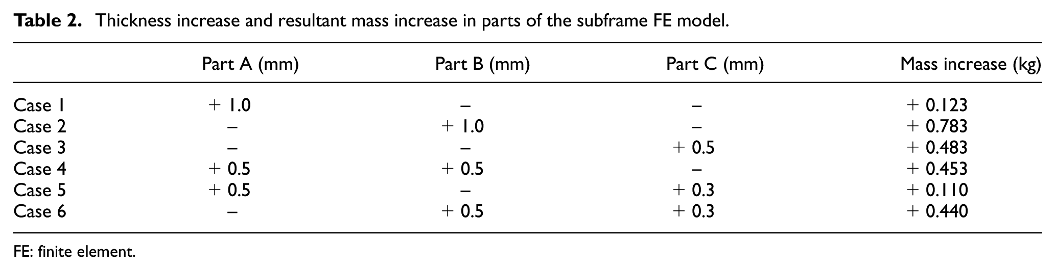
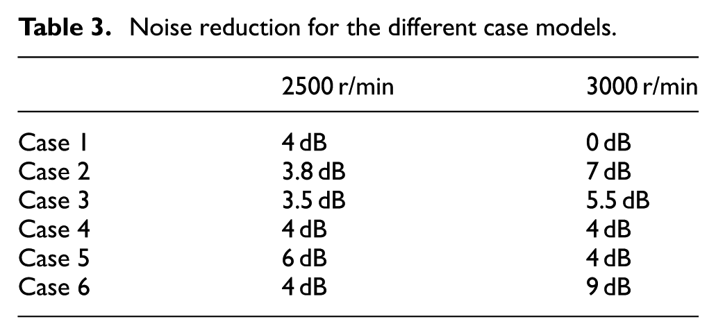
Reinforcement of the subframe thickness was also investigated as a potential noise mitigation measure in this study. Each of the beams was divided into A, B, and C parts, as shown in Figure 22. The effects of varying the thickness of each part were then examined (see Table 2). In Cases 1, 2, and 3, the thickness of parts A, B, and C were all increased by 1.0, 1.0, and 0.5 mm, respectively. In Case 4, the thickness of parts A and B was increased by 0.5 mm. In Case 5, the thickness of parts A and C was increased by 0.5 and 0.3 mm, respectively. In Case 6, the thickness of parts B and C was increased by 0.5 and 0.3 mm, respectively. The resultant mass changes of the subframe varied between 0.110 and 0.783 kg. The predicted interior noises for the different cases are shown in Figures 23 and 24, from which it can be observed that Case 2 was the most effective among the simple beam reinforcement cases (1, 2, and 3) for noise reduction for engine speeds of 2500–3200 r/min. Within the same engine speed range, Case 6 was the most effective among the multiple beam reinforcement cases (4, 5, and 6). The results are summarized in Table 3. Based on the findings of this parametric study, it is concluded that structural reinforcement to reduce the bending motion of the engine mount is an effective noise reduction strategy. Part B was particularly determined to be the most critical for this purpose.

Parts of the finite element model used for thickness modification of the subframe.
Thickness increase and resultant mass increase in parts of the subframe FE model.
FE: finite element.

Noise prediction results for Cases 1, 2, and 3: (a) second mode, (b) fourth mode, and (c) sixth mode.
Noise prediction results for Cases 4, 5, and 6: (a) second mode, (b) fourth mode, and (c) sixth mode.
Noise reduction for the different case models.
Conclusion
This study was performed to analyze the contribution of the engine vibration to the interior noise in a vehicle. For effective utilization of frequency response substructuring for this purpose, the vehicle structure was decomposed into the subframe and vehicle body. The subframe was analyzed using a finite element model, while the dynamic characteristics of the vehicle body were determined experimentally. The finite element model was verified by comparing its natural frequency and FRF with those of the real subframe model. It was then used to predict the interior noise by the substructuring method. The results showed that this prediction method was effective for frequencies of up to 300 Hz. Further contribution analysis revealed that the interior noise originating from the engine was dominant within frequencies of 70–110 Hz. Possible noise mitigation measures were also investigated using different case models comprising subframes of varying thickness. The case models were used to predict the internal noise by frequency response substructuring, and it was found that thickness reinforcement to reduce the bending modes was effective for noise reduction.
Footnotes
Academic Editor: Ling Zheng
Declaration of conflicting interests
The author(s) declared no potential conflicts of interest with respect to the research, authorship, and/or publication of this article.
Funding
The author(s) disclosed receipt of the following financial support for the research, authorship, and/or publication of this article: This research was supported by a grant from R&D Program of the Korea Railroad Research Institute, Republic of Korea.