
Abstract
For an in-wheel motor driving system with rubber bushings, the driving motor is integrated into the wheel. A magnet gap deformation of the motor will be inevitably caused by the road excitation, which will produce an unbalanced electromagnetic force and influence the power-train vibration. Furthermore, the rim is flexibly connected to the motor rotor by rubber bushings, and a strong coupling and nonlinear vibration of the power-train in all directions can be demonstrated under the electromagnetic excitations. Thus, a 14-degree-of-freedom coupling vibration model of the power-train is first developed for the in-wheel motor driving system with rubber bushings, including the bushing and bearing models. Then, the mathematical model is deduced using a Lagrangian approach. Finally, based on the model, a coupling vibration analysis is conducted under different electromagnetic force excitations. The results indicate that there are coupling vibration components in the torsional direction, except the one-time rotating frequency; however, in the bending direction, the vibration response includes a one-time rotating frequency component and an excitation frequency component of the electromagnetic force. Furthermore, the results indicate that the bushing plays an important role in reducing the power-train vibration, which has a positive effect on the improving vehicle dynamics.
Introduction
Torsional and bending vibrations are the primary forms of vibration in a vehicle power-train. In a traditional vehicle, the drive shaft is longer and there are relatively more transmission parts (such as the transmission, speed reducer, and differential). Furthermore, torsional and bending vibrations have been previously studied separately, and studies on torsional vibration were more common.1,2 These specific studies can simplify the model of the research object, which will allow for easier research. However, the two vibrations exist on the drive shaft simultaneously, and the vibration of the vehicle power-train indicates strong complicated coupling as well as nonlinear property due to the effect of the external force motivation and the imbalanced mass of the rotating parts. 3
For electric vehicles (EVs) driven only by the in-wheel motor (IWM), the chassis is quite different from that of traditional vehicles, and the driving motor is placed inside the wheel to further shorten the mechanical transmission 1 path from the electric motor to the driving wheel.4–6 Although this structure reduces the driving medium and improves the transmission efficiency, the deformation that will be caused by the road surface roughness (RSR) excitation in the magnet gap of the IWM is inevitable. The magnet gap deformation will produce an unbalanced electromagnetic force (EMF) and influence the vibration of the power-train. Furthermore, the rim is flexibly connected to the rotor of the IWM via a set of the rubber bushings, and a strong coupling and nonlinear response of the power-train vibration in all of the directions will be demonstrated under the EMF excitation.6,7 Therefore, a comprehensive understanding of the vibration rules for the power-train under the EMF excitation can provide theoretical guidance for the design and the vibration control.
In this article, a 14-degree-of-freedom coupling vibration model of the power-train for an IWM driving system with rubber bushings is initially developed using a Lagrangian approach. Based on the model, the effect of the EMF on the vibration response of the power-train is analyzed under different single harmonic excitation conditions.
IWM driving system and physical model
IWM driving system
The fundamental structure of the IWM driving system is illustrated in Figure 1. It is primarily composed of the IWM, rubber bushing, brake, bearing, rim, and so on. Uncharacteristically, there are flexible rubber bushings placed between the IWM stator and the support shaft, between the IWM stator and the suspension bracket and between the rim and the IWM rotor. Due to the rubber bushing, the IWM mass is isolated from the unsprung mass, and the bushings can absorb the RSR vibration.

IWM driving system with rubber bushings.
Physical model
Physical model of the rubber bushing
As depicted in Figure 1, bushing 1 is mounted between the IWM stator and the suspension bracket, and bushing 2 is placed between the IWM stator and the support shaft. The components connected by bushings 1 and 2 are static and do not transfer torque. Only bushing 3 is mounted between the IWM rotor and the rim and transfers the driving torque. Bushing 3 has a uniform distribution along the circumference direction of the wheel hub, as indicated in Figure 2.

Distribution of bushing 3.
As indicated in Figure 2, three annular bushings are subjected to the excitation force and the driving torque Tc from the IWM rotor. Although the wheel is driven by the driving torque, each bushing suffers from a radial force, and the deformation in the rubber bushing occurs in its radial direction. Therefore, the torsional stiffness of bushing 3 is the radial stiffness. To simplify the analysis, three rubber bushings are set to be equivalent to one flexible component, as indicated in Figure 3.

Equivalent structure.
Physical model of the power-train
The coupling vibration model is constructed based on the following assumptions:8,9
The IWM rotor and the rim are regarded as a rigid body, and both have 6 degrees of freedom, including 3 translational and 3 rotational degrees of freedom.
The connecting shaft of the IWM rotor and the rim is considered to be a rigid shaft without mass, and the mass of the shaft is shifted to the rotor and the rim equivalently.
The three rubber bushings are equivalent to one flexible component, for which the center is homocentric, and the rim and the mass are ignored.
The bearing is equivalent to the elastic support, and both the stiffness characteristics in the X and Y directions are the same, that is, kxx = kyy, as indicated in Figure 4.
For bushings 1 and 2, which do not transmit torque, only the radical stiffness and damping are considered in the X and Y directions. Here, bushings 1 and 2 are combined in parallel to demonstrate that the equivalent total spring and damper is k31x, k31y, c31x, and c31y.
The IWM rotor is supported on the stator through bearings 1 and 2, and the entire IWM is supported on the hub support shaft through bushings 1 and 2, whereas the rim is similarly supported on the hub support shaft through bearing 3. Therefore, the hub support shaft is selected as the basis for modeling.

Bearing model.
Based on the assumptions, a vibration model with 14 degrees of freedom is developed, as indicated in Figure 5.

Physical model of the power-train.
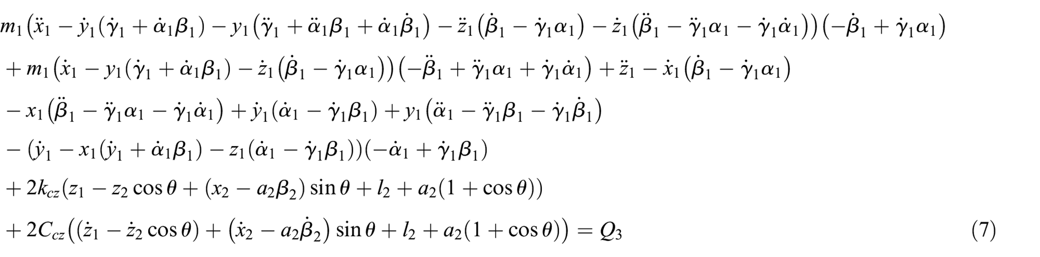
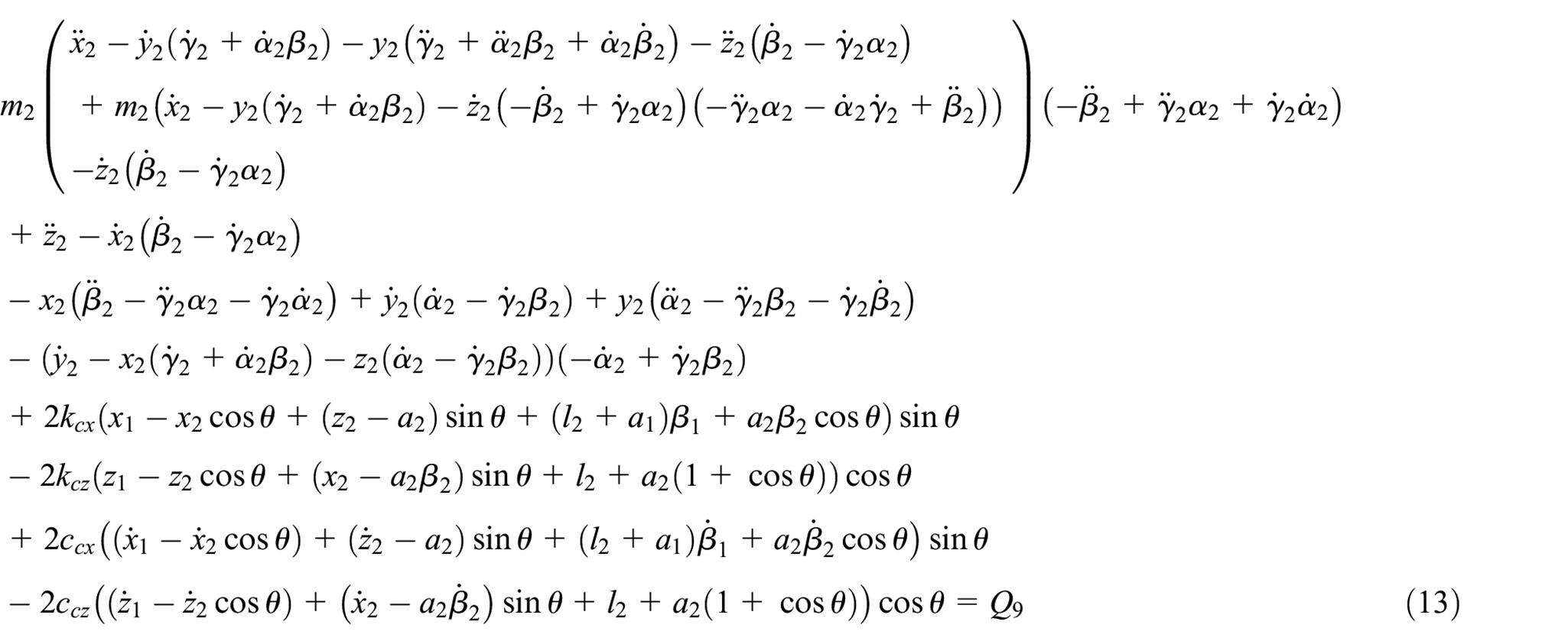
As illustrated in Figure 5, l1 and l2 are the distances from the geometric center of the IWM rotor to bearings 1 and 2, respectively; a1 and a2 are the distances from the bushing coupling points c− and c+ to bearing 3 support points b2 and b3, respectively; k31y and k31x are the stiffnesses in the X and Y directions, respectively; c31y and c31x are the damping in the X and Y directions, respectively; m1 is the total mass of the IWM rotor and the housing; m2 is the mass of the rim; and m3 is the mass of the IWM stator.
Mathematical model
Coordinates O1X1Y1Z1, O2X2Y2Z2, and O3X3Y3Z3 are initially defined for the development of the mathematical model based on the characteristics of the above physical model. The three coordinates are fixed onto the IWM rotor, rim, and IWM stator, and the coordinate origin is placed at the mass center of the corresponding component.
Kinetic, potential, and dissipation energy of the system
The generalized coordinate is defined as
Kinetic energy
The kinetic energy of the system can be given as follows

where mn is the mass of the IWM rotor and the rim; Idn is the rotary inertia of the IWM rotor and the rim about their own X-axis and Y-axis; and Ipn is the rotary inertia of the IWM rotor and the rim about their own Z-axis, where n = 1, 2.
Potential energy
A model of the three bearings is depicted in Figure 4. Bearings 1 and 2 have the same stiffnesses kx1 and ky1 in the X and Y directions, respectively. The stiffness of bearing 3 is different from 1 and 2 and can be represented using kx2 and ky2 in the X and Y directions, respectively.
The kinetic energy of the system can be given as follows

where kcx, kcy, and kcz are the three stiffnesses of the coupling point c in the three translational directions; kc1, kc2, and kc3 are the three stiffnesses of the coupling point c in the three rotary directions; and θ is the angle between the Z1-axis and the Z2-axis.
Dissipation energy
The dissipation energy of the system can be given as follows

where ccx, ccy, and ccz are the three damping coefficients of the coupling point c in the three translational directions and cc1, cc2, and cc3 are the three damping coefficients of the coupling point c in the three rotary directions.
Mathematic model of the system
The dynamic equation of the IWM driving system is determined based on the generalized Lagrange function. By assuming that the system has f degrees of freedom, the Lagrange function can be expressed as follows 10

where L = T − V; f is the number of the degrees of freedom; and Qj is the generalized force of the system, where f = 14.
A partial derivative calculation is conducted for each generalized coordinate vector, and 14 coupling vibration equations can be deduced as follows


Coupling vibration of the power-train under the EMF excitation
Parameter of the system
The main parameter of the system is listed in Table 1.
Vehicle parameters.
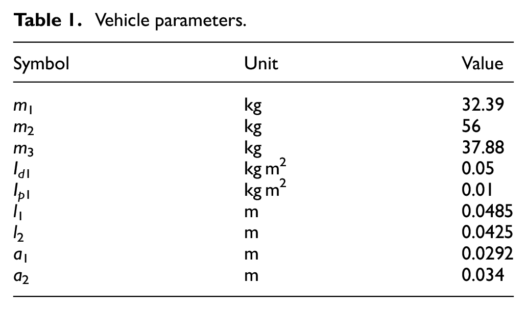
Figure 6 depicts the relationship between the displacement and the force of the three bushings (single), which is obtained from the experiments. As indicated in this figure, the force characteristic increases linearly with the displacement over a unique range of deformation. Therefore, for a simple analysis, a linear stiffness of the bushings is used in this article.

Displacement–force relation of the bushings.
Vibration response under the EMF excitation
Previous studies on the IWM EMF indicate that the EMF can be expressed as a series of harmonic functions with different amplitudes and frequencies.11,12 Therefore, an analysis on the effects of the EMF on the coupling vibration response of the power-train can be conducted by researching the effects of the single harmonic EMF excitation on the power-train.
During vehicle operation, the static and dynamic eccentricities of the IWM exist simultaneously, and the frequency of the unbalanced EMF in the X1 and Y1 directions is the same, that is, if the rotating frequency of the IWM is ωω = 2πfω, then the frequency of the EMF in the X1 and Y1 directions is kpωω (k = 1, 2, 3, …). 13 Thus, the effects of the single harmonic EMF excitation on the system vibration is investigated to understand the effects of the EMF on the coupling vibration response of the power-train, and it can be assumed that the EMF in the X1 and Y1 directions can be given as follows


where Fx0 and Fy0 are the amplitudes of the EMF in the X1 and Y1 directions, respectively; ωf is the EMF excitation frequency, ωf = kpωω; and p is the number of pole-pairs of the IWM, where p = 6.
The EMF acts on the stator and rotor of the IWM simultaneously. By substituting equations (19) and (20) into the Lagrange functions (5) and (6), the coupling vibration response of the system can be solved:
1. The rotating frequency of the IWM is ωω = 50 rad/s (k = 1), that is, the frequency of excitation is kpωω = 300 rad/s. By assuming that the amplitudes of the EMF in the X1 and Y1 directions are 100 and 200 N, respectively, that is, Fx0 = 100 N and Fy0 = 200 N, the bending and the torsional vibration of the power-train can be obtained in the time and frequency domains, as illustrated in Figures 7–9. Here, the result of the power spectral density (PSD) is obtained using the Fourier transform based on the result in the time domain.
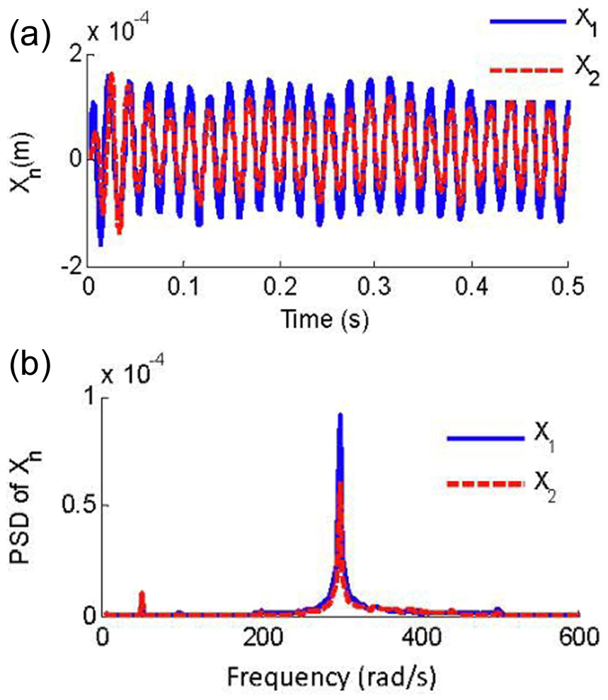
Vibration response of the IWM rotor and the rim in the Xn direction: (a) Results in the time domain and (b) results in the frequency domain.

Vibration response of the IWM rotor and the rim in the Yn direction: (a) results in the time domain and (b) results in the frequency domain.

Vibration response of the IWM rotor and the rim in the βn direction: (a) results in the time domain and (b) results in the frequency domain.
As depicted in Figures 7–9, if the rotating frequency of the IWM is ωω = 50 rad/s and the frequency of the excitation force is ωf = 300 rad/s, then the torsional frequency of the IWM rotor and the rim in the βn direction is 50, 250, and 350 rad/s, whereas the bending frequency of both is 50 and 300 rad/s. The rubber bushing causes the vibration amplitude of the rim transmitted from the rotor to decrease in each direction; however, a time delay exists in the response behavior of the rim due to the hysteresis of the rubber bushing. In addition to the one-time rotating frequency ωω, the same frequency component of the EMF excitation is produced in the translational direction. In the rotating direction βn, a frequency of 250 rad/s (250 rad/s = ωf − ωω) and 350 rad/s (350 rad/s = ωf + ωω) is excited by the excitation force along with the one-time rotating frequency ωω.
2. The rotating frequency is ωω = 50 rad/s (k = 2), that is, the frequency of excitation is kpωω = 600 rad/s. Similarly, by assuming that Fx0 = 100 N and Fy0 = 200 N, the bending and the torsional vibration of the system can be obtained in the time and frequency domains, as indicated in Figures 10–12.
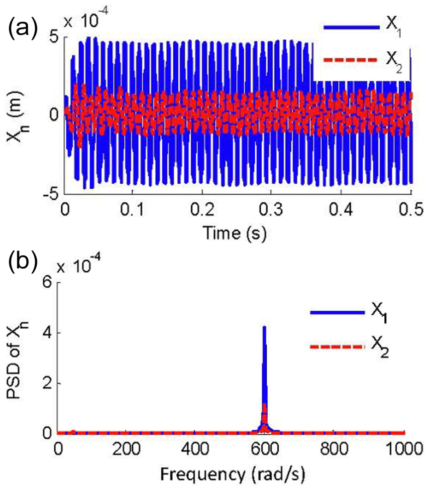
Vibration response of the IWM rotor and the rim in the Xn direction: (a) results in the time domain and (b) results in the frequency domain.

Vibration response of the IWM rotor and the rim in the Yn direction: (a) results in the time domain and (b) results in the frequency domain.

Vibration response of the IWM rotor and the rim in the βn direction: (a) results in the time domain and (b) results in the frequency domain.
As indicated in Figures 10–12, if the rotating frequency of the IWM is ωω = 50 rad/s and the frequency of the EMF is ωf = 600 rad/s, the torsional frequency of the IWM and the rim in the βn direction is 50, 550, and 650 rad/s, whereas the bending frequency of both is 50 and 600 rad/s, and the one-time rotating frequency ωω caused by the imbalanced mass of the rotating parts is relatively small. Similarly, in addition to the one-time rotating frequency ωω, the frequency component ωf is produced in the translational direction. In the rotating direction βn, a frequency of 550 rad/s (=ωf − ωω) and 650 rad/s (=ωf + ωω) is excited by the excitation force along with the one-time rotating frequency ωω. Furthermore, the rubber bushing causes the vibration amplitude of the rim transmitted from the motor to be reduced in each direction.
Discussion and conclusions
In this article, a 14-degree-of-freedom coupling vibration model is developed using a Lagrangian approach to study the power-train vibration of the IWM driven system with rubber bushings under the EMF excitation. Based on the coupling vibration model, further analysis on the effects of the EMF on the vibration response of the power-train is performed under a single harmonic excitation condition. A few conclusions can be obtained as follows:
Although the power-train of the IWM driving system with rubber bushings is relatively short, the IWM EMF caused by the road excitation will have an effect on the vibration characteristics of the power-train. Furthermore, the rim is flexibly connected to the IWM motor due to the set of rubber bushings, and strong coupling and nonlinear characteristics of the vibration in all of the directions will be demonstrated under external exciting forces, such as EMF excitation. Therefore, it is necessary to develop a bending–torsion coupling vibration model of the power-train that can accurately reflect the operating states.
The EMF excitation is related to the IWM rotating frequency ωω. The frequency of the EMF acting on the stator and the rotor in both the X and Y directions is ωf = kpωω, if a mixing eccentricity existed in the motor. Then, the torsional vibration component of the IWM rotor and the rim in the βn direction is |kp ± 1| ωω (k = 0, 1, 2, …), where the torsional component ωω is caused by the imbalanced mass of the rotating parts; the others are excited by the coupling effects of the IWM rotor and rim in the translational and rotational directions and the bending vibration components, including one-time rotating frequency ωω caused by the imbalanced mass of the rotating parts and the kp times frequency kpωω excited by the EMF.
The rubber bushing causes the vibration amplitude of the rim transmitted from the IWM to decrease and plays a role in decreasing the vibration of the power-train to a certain extent, which has a positive effect on improving vehicle dynamics. However, a time delay exists in the response behavior of the rim due to the hysteresis of the rubber bushing. Therefore, the time delay must be considered in the field of vehicle control, which will increase its difficulty. The characteristics (stiffness and damping) of the rubber bushing are not only critical to the coupling vibration of the power-train but also influence the ride comfort and handling stability of the vehicle. Thus, one of the future studies on the subject is optimally designing the rubber bushing based on the above factors.
Footnotes
Academic Editor: Hamid Taghavifar
Declaration of conflicting interests
The author(s) declared no potential conflicts of interest with respect to the research, authorship, and/or publication of this article.
Funding
The author(s) disclosed receipt of the following financial support for the research, authorship, and/or publication of this article: This research is supported by the National Natural Science Foundation of China (grant no.: 51405273), Shandong Province Higher Educational Science and Technology Program (grant no.: J14LB08) and sponsored by the Young Teachers Development Support Program for Shandong University of Technology (grant no.: 4072/115005) and the Natural Science Foundation of Shandong Province (grant no.: ZR2013EEM007).