
Abstract
In some finite element analysis studies of models of sections of the spine, the three-dimensional solid model is built by assuming symmetry about the mid-sagittal plane of the section, whereas in other studies, the model is built from the exact geometry of the section. The influence of the method used to build the solid model on model parameters, in the case of the cervical spine, has not been reported in the literature. This issue is the subject of this study, with the section being C2–C7, the applied loadings being extension, flexion, left lateral bending, and right axial rotation (each of magnitude 1 Nm), and the model parameters determined being rotation, intradiskal pressure, and facet load at each of the segments. When all the parameter results were considered, it was found that, by and large, the influence of solid model construction method used (exact geometry vs assumption of symmetry about the mid-sagittal plane of the section) was marginal. As construction of a symmetric finite element model requires less time and effort, construction of an asymmetric model may be justified in special cases only.
Introduction
Finite element (FE) analysis has been widely used in the biomechanical study of models of the cervical spine.1–3 This is because, among other things, FE analysis can be used to (1) obtain information about the underlying mechanism of dysfunction and injury of the cervical spine, (2) estimate parameters that cannot be determined from in vitro or in vivo biomechanical tests, (3) study the influence of variation of a given parameter of the model on model outputs, and (4) study the capability of a simulated treatment method for a given pathology of the spine to restore normal physiology of the spine.
FE analysis comprises four main features: a mesh of the solid geometry of the model, material properties, constraints, and applied loading. The cervical spine comprises hard tissues (seven vertebrae) and soft tissues (intervertebral disks, ligaments, and muscles). Muscles are not considered in the FE analysis with static loading. Three-dimensional (3D) geometry of the vertebrae and the disks are obtained from computed tomography (CT) scans taken from the spines of patients or cadavers. Geometry of ligaments is defined based on their origin and insertion. Material properties of each spinal component can be obtained from literature studies. Applied loading and constraints are similar to those experienced physiologically.
In constructing the 3D solid model geometry of a spine section, it is common to use CT scans of that section of a person or a cadaver. However, some researchers have used these scans together with an assumption of symmetry of the section about the mid-sagittal plane of the section,4–6 whereas others did not make such an assumption and, instead, used these scans together with the exact geometry of the section.7,8 To the best of the authors’ knowledge, there are no studies of the influence of the method used to construct the 3D solid model of a spine section on biomechanical responses of the model.
The purpose of this work was to conduct such a study with respect to a section of the cervical spine (C2–C7), with a series of clinically relevant applied loadings, each of magnitude 1 Nm, and the FE outputs being motion, intradiskal pressure (IDP), and facet loading at each of the segments in the model.
Materials and methods
Two FE models of a section of the cervical spine (C2–C7) were built, one using the exact geometry of the section (ASYM model) and another in which the geometry was approximated by assuming symmetry about the mid-sagittal plane of the section (SYM model) (Figure 1). MIMICS (MIMICS® Version 14.1; Materialise, Inc., Leuven, Belgium) software package was used for image processing the CT data, IA-FEMESH (University of Iowa, IA, USA) software package was used to generate the FE mesh of the model, and ABAQUS (ABAQUS®, Version 6.10-2; Abaqus, Inc., Providence, RI, USA) software package was used for the FE analysis. Lordosis was measured using the four-line Cobb method to be 25° and 22° for the ASYM and SYM models, respectively.

The finite element models: (a) asymmetric (ASYM) model and (b) symmetric (SYM) model.
FE model
Vertebrae
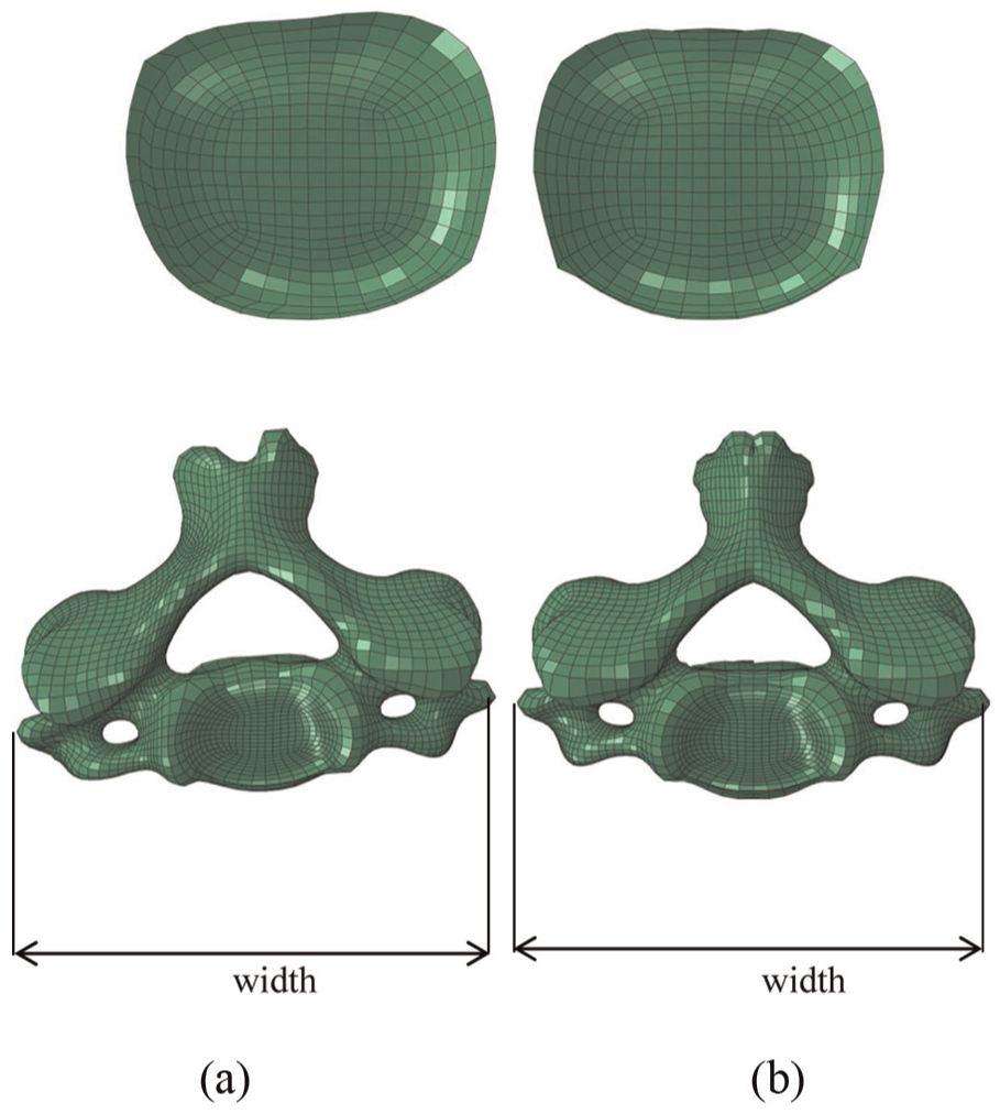
The 3D surface geometry of the vertebrae was obtained from CT scans of a 35-year-old man. The exact geometry of the vertebrae was used to construct the ASYM model. The geometry of the vertebrae for SYM model was generated based on the geometry of the ASYM model vertebrae. A mid-sagittal plane was generated to cut the geometry of the ASYM model. The location of the mid-sagittal plane was calculated based on the average widths of ASYM vertebrae. The width of each vertebra was measured between the left and right outer lateral borders (Figure 2; Table 1).
Circular mesh pattern, which was implemented on the C4 vertebral body: (a) ASYM model and (b) SYM model.
Comparison between the measured widths of the vertebrae (in mm), obtained using the asymmetric (ASYM) and symmetric (SYM) models.

For each vertebra, the outermost layer (approximately 0.5-mm thick) was assigned cortical bone properties, whereas the rest was assigned cancellous bone properties. The layer of element adjacent to the disk was assigned the material property of the bony endplate. The isotropic elastic constitutive model was used to simulate the material properties of all elements in vertebrae with approximate thickness of 0.6 mm.
Facet joints
Facet joints in each segment of the spine were simulated with 3D GAPUNI element library in ABAQUS. These elements transfer the force between nodes in a single direction as a function of the specified gap between them. The “softened contact” parameter, in ABAQUS, was used to adjust the force exponentially across the joint depending on the size of the gap. In each model, the same number of elements was used in each segment. For the SYM model, orientation of each element was the same on the each side of the mid-sagittal plane.
Intervertebral disks
Between each pair of vertebrae, 3D volumes were created to represent the geometry of an intervertebral disk. For the SYM model, the geometry of each disk was created by cutting its geometry in the ASYM model about the mid-sagittal plane. For each disk, the FE mesh comprised two parts: a mesh with a circular pattern representing the annulus fibrosus containing the fibers oriented at ±25° to the horizontal (as given in the literature) and a mesh in the core, representing the nucleus pulposus (NP). In each model, the same number of layers of elements (six layers) was generated for defining the annulus.
The layers of the annulus fibrosus were simulated with Neo-Hookean hyperelastic constitutive model. For each disk, the Rebar option, in ABAQUS, was used to simulate the behavior of fibers in the annulus. The “no compression” option, in ABAQUS, was used to allow the fibers to undergo only tension loading. For the fibers, isotropic elastic constitutive model was used. The fibers were oriented at ±25° to the horizontal according to the literature in the cervical region. Incompressible fluid elements were used to simulate fluid behavior of the nucleus.
Ligaments
In each model, five of the ligaments in the cervical spine were modeled, namely, anterior longitudinal ligament (ALL), posterior longitudinal ligament (PLL), ligamentum flavum (LF), capsular ligament (CL), and interspinous ligament (ISL). For each ligament, its point of origin and insertion in the spine section were taken from literature studies. For the SYM model, each of the ligaments was added to one side before mirroring about mid-sagittal plane. For the FE mesh, truss elements were used for each of the ligaments, with each element being assigned a cross-sectional area such that the total number of elements would produce the total area, as stated in literature reports. For each model, the same number of elements was used for a given ligament.
Each ligament was taken to be nonlinear elastic behavior, with low stiffness at low strain and higher stiffness at higher strain. The nonlinear behavior of the ligaments was simulated with “hypoelastic” constitutive model. This material model allowed axial stiffness to be defined as a function of axial strain.
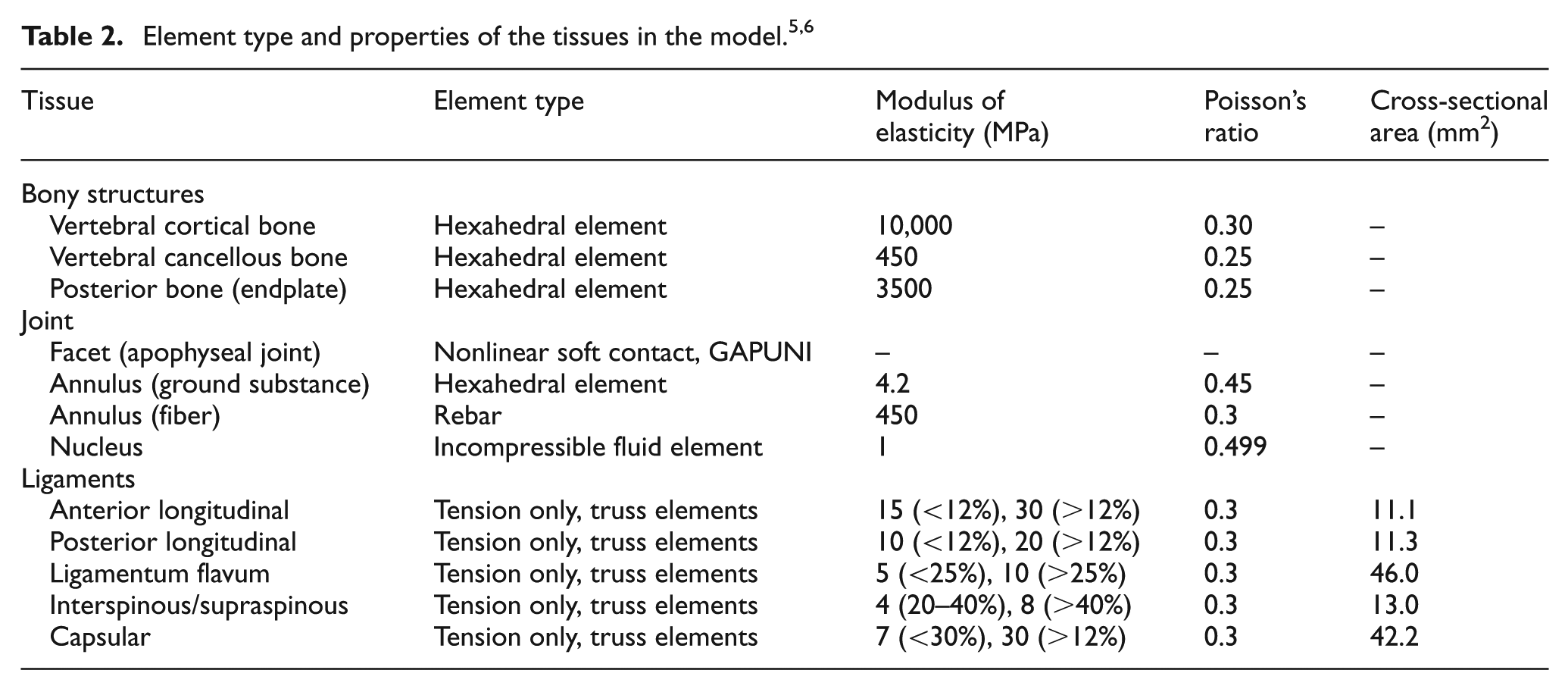
For each of the tissues, the same values of material properties were used in both models, and these values were taken from the literature (Table 2).
Loadings and boundary conditions
In each model, the bottom of the inferior endplate at C7 was fixed in all positions and directions and the loading was applied to a flying node (FN) that was created on the top of the odontoid process of the C2 vertebral body. These nodes were fixed in all positions and directions. For each model, a pure moment (each of magnitude 1 Nm) was applied individually in each of the three main directions: extension (EXT), flexion (FLEX), right lateral bending (RLB), and right axial rotation (RAR).
Under each of the applied loadings, the output parameters obtained were range of motion (ROM), IDP, and facet load (FL) at each of the segments in the model. Validation was done by comparing the ROM results obtained from the FE analysis on the ASYM model, 9 under each of the four types of applied loading, with corresponding ones obtained from a number of in vitro biomechanical studies.10–12
Results
In a previous report, 9 it was shown that ASYM model was validated. The ASYM model underestimates ROM in 45% of the sets (9 out of 20 sets), with this underestimation being (1) consistent when RLB was applied and (2) the largest (25%) at C2–C3 under RAR (Figure 3). The ASYM model underestimates IDP in 60% of the sets (12 out of 20 sets), with this underestimation being (1) consistent when EXT was applied and (2) the largest (50%) at C2–C3 under EXT (Figure 4). The ASYM model underestimates FL in 40% of the sets (6 out of 15 sets), with the largest underestimate being ~75% at C5–C6 under RAR (Figure 5).

Summary of the segmental motion results.

Summary of the intradiskal pressure results.

Summary of the facet load results.
Discussion
An FE model of the cervical spine can be constructed based on the exact geometry or using an assumption in the geometry. Symmetry about the mid-sagittal plane is one of the widely used assumptions in FE models of the cervical spine. On the other hand, understanding the effect of such an assumption, that is, symmetry in the mid-sagittal plane, is of high importance to trust on the output of the FE model. The lack of such a study was the motivation for this work, which was an investigation of the influence of the method used to construct the solid model of a cervical spine section (exact geometry vs assumption of symmetry) on biomechanical responses of the model.
Each of the biomechanical responses determined in this work is clinically relevant. ROM indicates the ease with each a person can perform various activities of daily living, such as reading and combing of hair. IDP and FL are measures of load sharing by a segment during performance of these activities.
For each of the biomechanical outputs determined, the difference in results obtained when ASYM model was used compared to the case when SYM model was used was, on the whole, marginal. Assumption of symmetry about the mid-sagittal plane reduces the time for constructing the FE model of the cervical spine. Therefore, the time spent on creating the hexahedral mesh on the SYM model becomes approximately half of the ASYM model due to complexity in the cervical spine geometry. However, in this work, the number of nodes and elements in the SYM model was higher than in the ASYM model; as such, the simulation time for the former model was longer.
This study has three limitations. First, the solid model was constructed using CT scans from one patient. Thus, the results are patient-specific. Second, the bony tissues, annulus fibrosus, and NP were each modeled as isotropic, elastic materials. Use of sophisticated material constitutive models, such as transverse isotropy for cortical bone, poroelasticity for cancellous bone, and hyperelasticity for NP, could have enhanced the FE analysis. Third, muscles were not included in the solid model, and left lateral bending moment and left axial rotation loadings were not applied; in each of the loadings, a compressive load representing the weight of the head was not included. Addition of each of these features would have further enhanced the analysis.
Conclusion
For a model of a section of the cervical spine (C2–C7), FE analysis results obtained from imposing a series of clinically relevant applied loadings (EXT, FLEX, RLB, and RAR) on the model, each of magnitude 1 Nm, show that the influence of the method used to build the 3D solid model (exact reconstruction of geometry vs reconstruction of geometry that assumed symmetry about the mid-sagittal plane of the section) was, on the whole, moderate.
Footnotes
Academic Editor: Libardo Vicente Vanegas Useche
Declaration of conflicting interests
The author(s) declared no potential conflicts of interest with respect to the research, authorship, and/or publication of this article.
Funding
The author(s) received no financial support for the research, authorship, and/or publication of this article.