
Abstract
The service life of a gear-type oil pump with variable displacement is affected by the reliability of its drive system. To analyse the reliability of the drive system and improve the service life of the oil pump, a virtual prototype model was established based on real conditions and multi-body dynamic theory. The model was validated according to bench test results. And simulation results were in good agreement with test results. A numerical method was used to simulate the dynamics model and the dynamic meshing forces of gear pairs were obtained. A reliability evaluation model of the drive system was built. The reliability of each part and the entire drive system were calculated. And system reliability was analysed and discussed when 45 steel or 40Cr was utilised as the material for the drive system. The results provided a foundation for the reliability design and the dynamic optimisation of a gear-type oil pump with variable displacement.
Introduction
Compared with a fixed displacement pump, a variable displacement oil pump can reduce energy consumption (by 3%) and CO2 emissions. 1 Research on variable displacement pumps has focused on vane pumps, gear pumps and piston pumps. Given their light weight, low cost and high operation efficiency, gear-type oil pumps with variable displacement have been applied in automobile engines. The service life of an oil pump is mainly determined by the reliability of its drive system. Therefore, research on the reliability of oil pump drive systems is significant.
Product reliability has a direct relationship with quality and competitiveness. Thus, manufacturers spend a huge amount of money to improve the reliability of their products. 2 In the past decades, research, analysis and design on mechanical system reliability had made significant achievements. At present, both domestic and foreign scholars have achieved considerable progress in improving the reliability of drive systems. Based on the rules of mono-source fuzzy numbers which can be used into the solution of fuzzy stochastic finite element equations in engineering, Liu and Chen 3 proposed a new method to appreciate the structural fuzzy failure probability. Considering the correlation of failure modes, Su et al. 4 proposed a frequency reliability analysis method for rotor systems. He determined the resonance vibration failure probability of a rotor system through numerical integration. Liu et al. 5 calculated and evaluated the reliability of the key parts of a differential system, using 45 steel or 1Cr18Ni9Ti as the material for the worm shaft. System reliability was then analysed and discussed. Du et al. 6 established a reliability analysis model for harmonic drives. Zhang et al. 7 used a second-order inelastic analysis method to evaluate the strength and serviceability reliabilities of steel. To improve the reliability of an axle drive shaft, Shin et al. 8 applied stress relief grooves on the drive shaft and analysed its reliability by conducting finite element analysis. The reliability of the drive shaft was improved significantly and fatigue life increased by nearly 3.3 times. Wang et al. 9 built a dynamic reliability model of the gear drive system of a wind turbine and calculated the dynamic reliability of the system. The results of the developed method were then compared with those of the Monte Carlo method; the findings provided the foundation for the design of a wind turbine gear drive system. Teng et al. 10 established a three-dimensional (3D) model of a planetary gear box. Gear tooth surface contact stress and tooth root bending stress were obtained using finite element analysis software. This previous research showed that excessive contact stress was directly responsible for gear failure. System reliability evaluation was also completed, which could provide guidance in engineering practice. Alemayehu and Ekwaro-Osire 11 presented a novel probabilistic multi-body dynamic analysis method and then analysed and calculated random variables and system reliability. Nejad et al. 12 proposed a method for analysing the gear tooth root of the drivetrains of a wind turbine under long-term fatigue damage. The short-term stress cycle was obtained, and finally, the reliability of the drive system was calculated under load effect. Song and Wang 13 presented a reliability simulation model of the electric drivetrain of hybrid electric vehicles based on MATLAB. This model could predict the reliability of a system and reduce power loss. Kim et al. 14 presented a selection search technology based on a genetic algorithm to complete system reliability analysis and system failure probability calculation. The failure proportion of the components was also evaluated. Complex systems require high reliability in the operation and design processes. Peng et al. 15 developed a reliability analysis method for systems with multi-level qualifications, lifetime prediction and data degradation.
Above all, the system reliability can be obtained by theoretical calculation or simulation analysis. The results of theoretical calculation can be concluded with empirical formula, which needs to establish the reliability model of the object and substitute into the relevant values. The process characteristic of theoretical calculation is simple and convenient. So that it is applied to deal with practical problems by engineers. According to the finite element model, the system reliability results can be drawn. While the parameters of all the parts are known, finite element model can be built. Actually, it is difficult for the engineers to obtain all the parameters. Therefore, the empirical formula is used to calculate the reliability of the drive system.
Structural reliability analysis is typically based on a model that describes the response of a system, such as stress, maximum deformation and contact force time series, as a function of random variables.16,17 In this study, the contact force of a gear and the bending torque of a shaft were used as random variables to analyse the reliability of a drive system. In 1950, Tuplin 18 laid the theoretical basis for gear system dynamics research. They proposed the concept of equivalent tooth meshing stiffness, among others. The results of their research significantly promoted the development process in the field. In 1998, Kahraman and Singh 19 built a lumped-parameter model and a finite element model of a planetary drive system by considering the nonlinear and time-varying meshing stiffness of the system. Ambarisha and Parker 20 analysed nonlinear phenomena such as chaotic motions, period-doubling bifurcations and mode jumping. Based on a 4-degree-of-freedom (DOF) dynamic model of transmission, Nikolić 21 proposed a dynamic contact stress/strain state analysis method, adopted a nonlinear finite element contact formulation method, used CODE-ASTER and developed modules for a novel software.
At present, research on the reliability of gear-type oil pumps with variable displacement remains scarce. Most studies on this topic have focused on the theoretical perspective, used an empirical formula to calculate the contact force between the gear and the bending torque of a shaft and rarely considered the contact force of the gear and the bending torque of the shaft of drive systems during operation. Moreover, these studies cannot accurately obtain the fatigue reliability of drive systems.
In this article, the drive system of a gear-type oil pump with variable displacement is selected as the object. A multi-body dynamics model of the oil pump is established using virtual prototyping software ADAMS. The typical working conditions of the oil pump are applied to obtain the contact force time series and the torque time sequence in the gear meshing process with the dynamic model. A reliability model of the drive system and its key parts is established. The reliability of the model is calculated. To improve system performance, the reliability of the drive system is analysed using two different materials.
Structural parameters of the gear-type oil pump with variable displacement
The structural diagram of the gear-type oil pump with variable displacement is shown in Figure 1. In this two-stage pressure pump, the pressure is adjusted by controlling the amount of oil obtained by the pump gears. The amount of oil from the pump is determined by the relative displacement of the pump gears (particularly the axial movement of the driven gear). The capability to refuel is strongest when the pump gears are meshing and weakest when the maximum axial displacement of the driven gear is reached. The axial movement of the driven gear is caused by the pressure difference between the piston top and the bottom face. Such difference in the pump is caused by changes in the hydraulic control system. System oil pressure is managed by the engine control unit according to engine speed through the solenoid control valve. When engine speed reaches 3500 r/min, the oil pump switches to high voltage and the output oil pressure is 0.33 MPa. By contrast, when engine speed is less than 3500 r/min, the oil pump is under a low-pressure condition and the output oil pressure is 0.18 MPa.

Structural diagram of the gear-type oil pump with variable displacement.
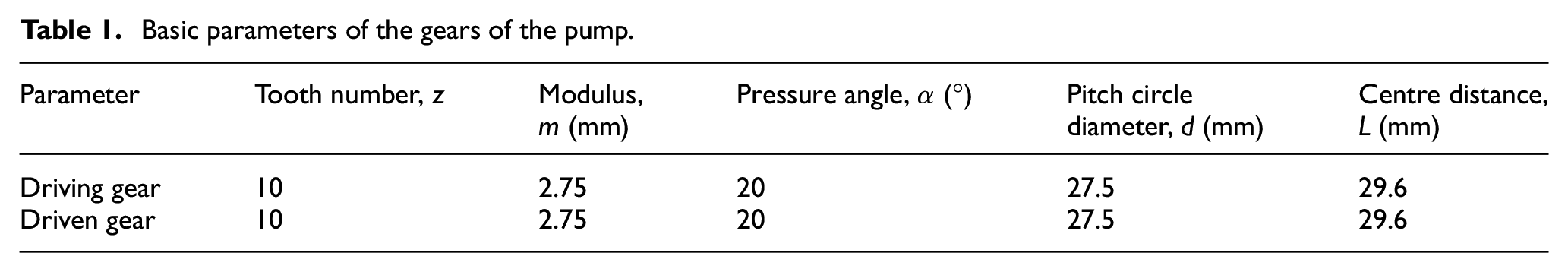
The gear drive system is the main component of the gear-type oil pump with variable displacement. In Figure 2, basic dimensions of each components of the drive system are drawn.

The drive system model.
The difference in the amount of oil is determined by the change in the relative displacement of the master-slave gear in the drive system. As the axial displacement of the driven gear increases, the width of the gear tooth becomes small and the capability to supply oil is poor. The reliability of the gear drive system is affected by the load force of the oil supply and the normal use of the oil pump. Therefore, reliability research on the gear drive system of oil pumps is highly significant. This study uses the drive system of a pump as a case analysis. The parameters of the gears of the pump drive system are provided in Table 1.
Basic parameters of the gears of the pump.
Establishing the multi-body dynamics model
Multi-body dynamic theory
The Lagrange motion equation of the gear-type oil pump with variable displacement was built according to the mechanical system model. This Lagrange equation and the corresponding constraint equation are expressed, respectively, as follows 22


where K is kinetic energy of the system, qj is generalized coordinates of system, ψi is constraint equations of the system, Fj is generalized force and λi is Lagrange multiplier array.
Multi-body dynamics model
Constraint determination
The mechanical model of the pump is established using 3D software. To simulate the operation process, the material of each part is redefined using multi-body dynamics software ADAMS. Constraint relationships among major parts are then determined based on the working principle of the oil pump. The specific constraint types are listed in Table 2.
Constraint relations among the major components of the gear-type oil pump with variable displacement.
Apart from the aforementioned major constraints, contact forces also occur between the driven gear and the driven shaft to adjust meshing position. Simultaneously, the meshing gears transmit power through such contact forces.
Contact force definition
Contact force is defined using two methods: the compensation method and the impact-function method. The former needs to determine the penalty and compensation coefficients preliminarily. 23 The latter calculates contact force between two motion artefacts based on Hertz elastic collision, which consists of the damping force caused by relative velocity and the elastic force produced by tangential velocity. The algorithm is suitable under continuous contact conditions and is mostly adopted to calculate gear meshing force. 24 In this study, we select the impact-function method to calculate gear contact force, the function expression of which is as follows

where K1 is contact stiffness coefficient of the master-slave gear, q is actual distance in the process of collision between master-slave gear, q0 is initial distance, e is force exponent, C is damping and d is penetration depth.
Based on multi-rigid-body dynamics theory and the working principle of the oil pump, the relationship among the main components is determined, the boundary is defined and the appropriate load is added. Finally, the research object of the multi-body dynamic model is established, as shown in Figure 3.
Dynamic model of the gear-type oil pump with variable displacement.
Model verification
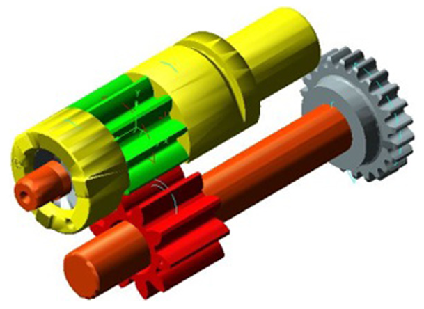
To verify the prototype model, the experiment platform of the gear-type oil pump with variable displacement is established, as shown as Figure 4. In this study, the torque of the drive shaft is regarded as an effective criterion.
Torque test platform of the gear-type oil pump with variable displacement.
The working speed range of the gear-type oil pump with variable displacement is 600–7000 r/min. In this study, eight operating conditions are selected to analyse the torque of the drive shaft. These conditions are 1000, 2000, 3000, 3500, 4000, 5000, 6000 and 7000 r/min. The results of the analyses are provided in Figure 5.

Experimental and simulation results of the torque of the driving shaft.
As shown in Figure 5, the simulation results are in good agreement with the experiment results. Maximum deviation appears at high speed. The deviation remains within the acceptable range. Therefore, the prototype model established in this study is effective and can be used in the reliability analysis of pump drive systems.
Reliability calculation of key parts
Based on the working principle of the research object, the drive system includes the following key parts: driving wheel, driving shaft, driving gear, driven gear and driven shaft.
Reliability assessment model of gears
The main failure forms of gears include gear tooth breakage, fatigue pitting, tooth face agglutination, tooth surface abrasion and tooth surface plastic deformation. 25 For enclosed transmitting gears under normal conditions, tooth surface contact fatigue damage and tooth root bending fatigue failure are the main failure modes. Therefore, we choose tooth surface contact fatigue reliability and tooth root bending fatigue reliability to calculate gear reliability.
Tooth surface contact fatigue reliability
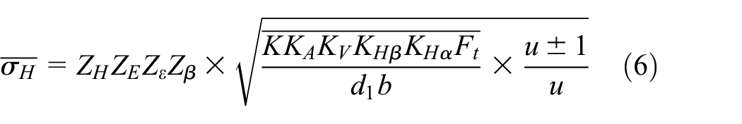
Based on the literature, 26 gear tooth surface contact stress can be calculated as follows

Meanwhile, gear surface contact fatigue strength can be calculated through the following equation

Using the variation coefficient method, the average contact stress, the coefficient of variation and the standard deviation are calculated, respectively, as follows


Similarly, the average contact fatigue strength, the coefficient of variation and the standard deviation can be calculated, respectively, as follows


According to stress–strength interference theory, the reliability coefficient of tooth contact fatigue strength is calculated as follows

Based on central limit theorem, if the studied object is explained by many independent random variables, then the affection of each variable is minimal and distribution is roughly normal. Consequently, the distribution of reliability is normal. Therefore, the tooth surface contact fatigue reliability function can be expressed as follows

Tooth root bending fatigue reliability
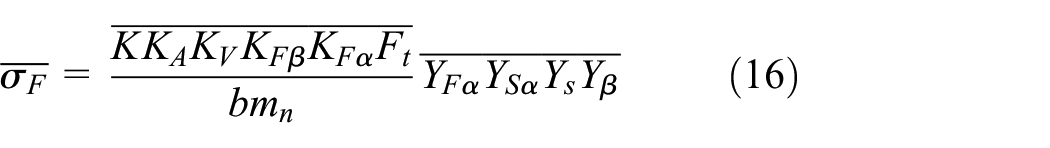
According to the literature, 27 the bending stress of the tooth root can be calculated as follows
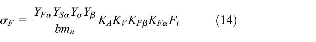
Meanwhile, the bending fatigue strength of the tooth root can be calculated as follows

Using the variation coefficient method, the average bending stress, the coefficient of variation and the standard deviation are calculated, respectively, as follows


Similarly, the average bending fatigue strength, the coefficient of variation and the standard deviation are calculated, respectively, as follows


Thus, according to stress–strength interference theory, the reliability coefficient of tooth bending fatigue strength is calculated as follows

In the same manner, the reliability function of tooth surface bending fatigue can be expressed as follows

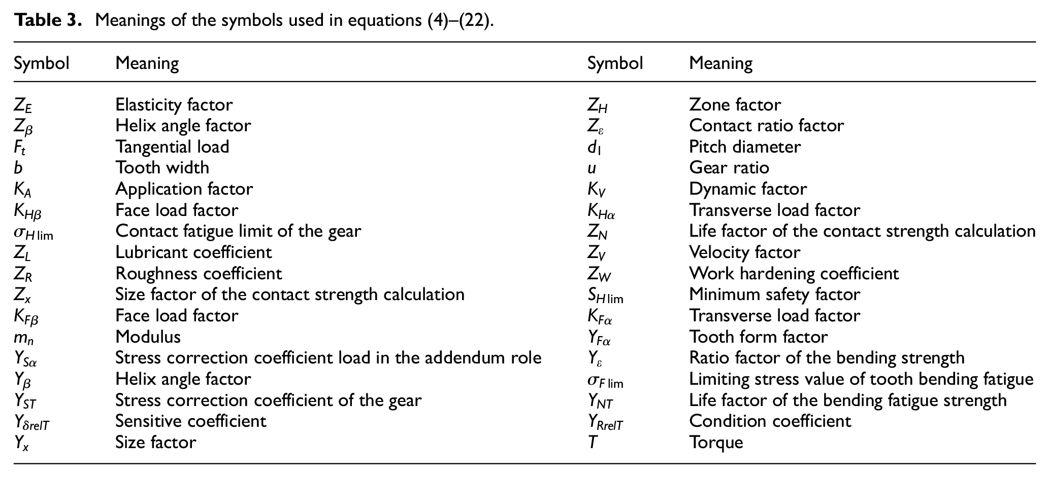
Meanings of the symbols used in equations (4)–(22) are shown in Table 3.
Meanings of the symbols used in equations (4)–(22).
Reliability assessment model of the shaft
The research object of the driving shaft is a rotating axis, which is simultaneously subjected to bending moment and torsion. Reliability is calculated by considering bending and torsion strengths. The bending moment of the rotating axis is calculated as follows

Where MH is horizontal bending moment and MV is vertical bending moment.
Bending stress can be calculated as follows

Shear stress can be calculated as follows

The combined of the bending and torsional stresses of the shaft can be calculated as follows

The distribution of the bending and torsion fatigue stresses of the shaft is normal. Hence, the average mean stress and stress amplitude are calculated, respectively, as follows
The average combined of bending and torsional stresses is calculated as follows

The standard deviation of bending and torsional stresses is calculated as follows

The fatigue limit of the shaft can be calculated as follows

where σ−1 denotes fatigue limit, k denotes reduction factor of the fatigue strength; ε denotes size factor and βα denotes surface quality coefficient.
The average fatigue strength can be calculated as follows

The standard deviation of the fatigue strength of the shaft can be calculated as follows

The reliability coefficient of the shaft is calculated as follows

Similarly, the reliability function can be expressed as follows

In view of the requirement of the enterprise and the running condition of the vehicle, the working speed of the oil pump is 600–7000 r/min. the pump is in a low-pressure state at 600–3500 rpm. The pump automatically switches to a high-pressure state in excess of 3500 r/min. Meanwhile, as the tooth width of a gear changes, the contact force of the gear also changes rapidly. While the highest rotational speed is 7000 r/min, the contact force of the gear is the largest. Therefore, these two conditions are chosen in this study to calculate the reliability of the drive system. Simulation time is set to 1 s and simulation step is set to 0.001 s. The results of the dynamic contact force of the gear under the two conditions, that is, 3500 and 7000 r/min, are presented in Figures 6 and 7, respectively.

The dynamic contact force of the gear at 3500 r/min.
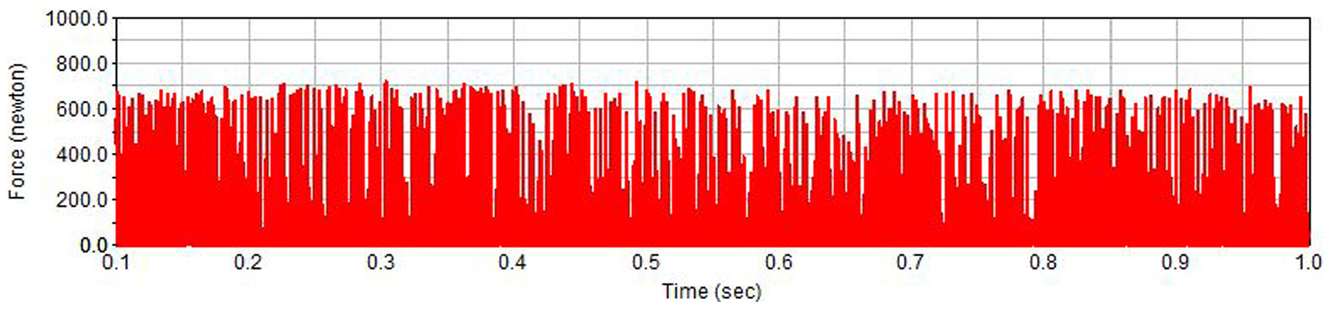
The dynamic contact force of the gear at 7000 r/min.
The average contact force at 3500 and 7000 r/min is 264.97 and 326.67 N, respectively. The simulation contact force consists of two mutually perpendicular force components, namely, tangential force and radial force. The tangential force under the two conditions is
The average tooth surface contact stress under the two conditions is, respectively, as follows

The variation coefficient of contact stress is calculated as follows

Meanwhile, the standard deviation of contact stress under the two conditions can be calculated, respectively, as follows
The average contact fatigue strength is calculated as follows

The variation coefficient of contact fatigue strength is calculated as follows

The standard deviation of contact fatigue strength is calculated as follows:

The reliability coefficient under the two conditions is calculated respectively as follows

Reliability R, which exhibits standard normal distribution, can be calculated from the normal distribution chart as follows

The average tooth root bending stress is calculated, respectively, as follows

The variation coefficient of bending stress is calculated as follows

The standard deviation of bending stress is calculated, respectively, as follows

The average tooth bending strength is calculated as follows

The variation coefficient of bending strength is calculated as follows

The standard deviation of bending strength is calculated as follows

The reliability coefficient is calculated, respectively, as follows

Reliability is calculated as follows

The tangential force under the two conditions is calculated, respectively, as follows

The bending moment in the horizontal plane is calculated, respectively, as follows

The bending moment in the vertical plane is calculated, respectively, as follows

The bending moment of the shaft is calculated, respectively, as follows

The average combined stress is calculated, respectively, as follows

The standard deviation of the combined stress is calculated, respectively, as follows

The average strength is calculated as follows

The standard deviation of shaft strength is calculated as follows

The reliability coefficient of the shaft is calculated, respectively, as follows

The reliability of the shaft is calculated, respectively, as follows

Reliability assessment model of the drive system
The reliability evaluation of independent failure involves the failure of each component of a system. The failure of each part is an independent event. The traditional system reliability model is founded on the premise of independent failure. However, most mechanical systems are dependent and affected by unit reliability and unit combination. 2
A system will yield varying reliability results using the same elements in different combinations. In this study, the drive system of the pump is a series system. For series systems, overall failure occurs if a unit of the system fails. The reliability of a series system is illustrated in Figure 8.

A series system of n units.
As shown in Figure 8, each unit is required to operate properly at the same time to ensure the normal operation of a series system. If

In reality, correlation exists among the components of a system. Therefore, the reliability of the whole system can be expressed as follows

where Φ and φ are probability distribution function and probability density function of standard normal distribution, respectively; Zβ is reliability index; and ρ is correlation coefficient.
Considering the failure probability of each part and based on the definition of a series system, the drive system of the gear-type oil pump with variable displacement can be simplified into five units in a series, namely, a driving wheel, a driving shaft, a driving gear, a driven gear and a driven shaft. The reliability block diagram of the drive system is shown in Figure 9.

Reliability block diagram of the drive system of the gear-type oil pump with variable displacement.
Considering the interaction among system units, the reliability of the drive system based on gear couple RZ of equation (37) can be simplified as follows 28

Assuming that the reliabilities of both the driving wheel and the driven shaft are constant, satisfy design standards and are set to 99%; then, the tooth surface contact fatigue reliabilities and the tooth root bending fatigue reliabilities of the driving gear and the driven gear are equal. The reliability of the drive system can be calculated as follows

Optimisation analysis of the drive system
As indicated by the reliability result, the drive system can satisfy engineering standards. However, the reliability value of the drive system is low when the oil pump works under the limiting working condition, and thus the system cannot work for a long time. To improve product quality, enhance competitiveness and satisfy the needs of a product for a long period under high speed, the reliability of the drive system is analysed and calculated using 45 steel and 40Cr. This work will provide an optimisation method for product design in the future. The properties of the two materials and processing methods used are provided in Table 4.
Material properties and heat treatment method.

The reliability of the drive system is calculated using different materials for the shaft and the gear, as shown in Table 5. The results are also provided in Table 5.
Reliability of the drive system using different materials.
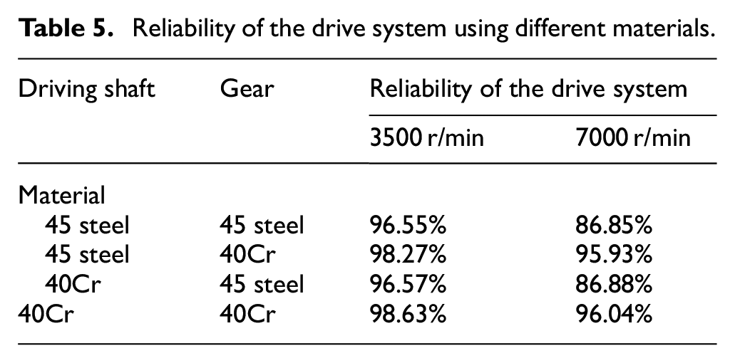
As shown in Table 4, three cases are used to change the reliability of the drive system apart from the initial design:
Case 1. The shaft is made of 40Cr; the reliability of the drive system improves inconspicuously.
Case 2. Both the shaft and the gear are made of 40Cr; the reliability of the drive system improves most obviously among the three cases.
Case 3. The gear is made of 40Cr; reliability obviously increases. In this case, the calculation result is similar to that of the reliability of Case 1 and the difference can be ignored.
Under the premise of satisfying the aforementioned requirement, economic feasibility will be affected by the complexity of the structure and the high reliability of the system.29–30 Therefore, 40Cr should be used as the material for the gear instead of 45 steel, whereas 45 steel should be used as the material for the shaft. The reliability of the drive system is improved and the method is economically feasible.
Discussion and conclusion
Based on Multi-body dynamics and working principle of a gear-type oil pump with variable displacement, a dynamic model of the research object was established by employing a virtual prototype. To validate the dynamic model, a test bench was built. Based on experiment results, basic parameters of the oil pump were obtained. And simulation results had good consistency with the experiment results. Comparing simulation results with experiment results, the simulation based on dynamic model can truly reflect working conditions of the pump and the results achieved were accurate and reliable. The contact force between the gear and the torque of the driving shaft was simulated under different conditions to analyse and evaluate the reliability of the drive system. And the reliability of the gear was calculated using the variation coefficient method and based on the stress–strength interference theory under the typical condition. The reliability of the driving shaft was calculated using the bending moment and torque obtained from the simulation. Considering the interaction among the drive system units, the reliability of the drive system was estimated. The reliability of the research object under two typical conditions was higher than the allowable value and satisfied the engineering requirements. The reliability of the drive system was analysed using two different materials, 45 steel and 40Cr, under the condition that the weight of the oil pump remained constant. And considering the reliability and economic feasibility, 40Cr should be used as the material for the gear instead of 45 steel, whereas 45 steel should be used as the material for the shaft. The result of this study provides theoretical support for further optimising the design of gear-type oil pumps with variable displacement.
Footnotes
Academic Editor: Anand Thite
Declaration of conflicting interests
The author(s) declared no potential conflicts of interest with respect to the research, authorship, and/or publication of this article.
Funding
The author(s) disclosed receipt of the following financial support for the research, authorship, and/or publication of this article: This work is supported by the Program for the Research Fund for National Nature Science Foundation of China (NSFC 51175320), Shanghai Natural Science Founds (14ZR1418600), the Shanghai Young University Teachers Training Aid program by Shanghai Municipal Education Commission (ZZGJD13027) and the Teaching Building Project by Shanghai University of Engineering Science (2013–2015).