
Abstract
Structural synthesis of kinematic chains is one of the most important and challenging mathematical problems in the field of conceptual design stage of mechanisms. In this article, an automatic topological structural synthesis algorithm has been proposed for planar simple joint kinematic chains. At first, the planar simple joint kinematic chains can be represented by single-color topological graph and corresponding link-joint incident matrix. Then, the corresponding incident matrices of planar simple joint kinematic chains with special input parameters can be formed with the single kinematic chain adding method with the help of isomorphic identification. Finally, based on the procedure for the single-color topological graph automatic drawing, an automatic topological structural synthesis algorithm of planar simple joint kinematic chains with specified degree of freedom F and number of links n can be synthesized in batch, while there are several examples to show the effectiveness of this method.
Keywords
Introduction
Structural synthesis is the first and most important stage in the mechanical conceptual design progress.1–4 It is the original innovation of mechanical systems and provides large numbers of optional structure types when new mechanisms are created. The structural synthesis of planar mechanisms aims at generating a complete list of kinematic structures of mechanisms with specified input parameters, which are free from isomorphic kinematic chains. Since 1960s, structural synthesis of kinematic chains has been attracted by many scholars to research on. 5
The concept of Assur-groups and mechanisms can be composed by introducing the corresponding Assur-group which is proposed by Assur.6–8 Structural synthesis method is based on Franke’s Notation proposed by Davies and Crossley 9 and Soni, 10 with which 40 types of 9-link 2-degree of freedom (2-DOF) and 230 types of 10-link 1-DOF planar simple joint kinematic chains (PSJKCs) are synthesized in batch. The topological graph theory on the study of PSJKCs is introduced in the papers,11–13 and later the synthesis method based on topological graph theory is developed widely and has become the most popular structural synthesis approach. Tuttle et al.14,15 have proposed the approach relied on the finite group theory and the PSJKCs with 6–12 links and 1–3 DOFs are generated. The permutation group approach for the structural synthesis of PSJKCs is presented by Yan and colleagues.16,17 The dual graph approach is proposed by Sohn and Freudenstein, 18 the hamming number technique by Rao,5,19 and the single opened chain (SOC) theory to synthesize PSJKCs by Yang and colleagues.20,21 Those methods also expound some new ideas for the structural synthesis of PSJKCs. Butcher and Hartman 22 have developed the efficient enumeration and hierarchical classification of PSJKCs, and Sunkari and Schmidt 23 have put forward a structural synthesis method of PSJKCs by adapting the Mckay-type algorithm. Ding et al.24–26 have raised a structural synthesis theory of planar simple and multiple joint kinematic chains based on the topological model. With this method, some specific planar kinematic chains are obtained. Chu and colleagues27–35 have put forward a unified topological model with the help of SOC theory to synthesize planar simple and multiple joint kinematic chains. According to the incident matrixes (IMs) of kinematic chains corresponding to specified DOFs F, number of links n and the total multiple joint factors P can be automatically synthesized.
From the research status above,5,6–26 the structure synthesis of PSJKCs has lingered at a relatively low level in terms of automation in the past. Common features of structural synthesis approaches in general are that the generated kinematic structures are depicted in the form of algebraic representations (such as adjacency matrix (AM) or IM) in output and designers can hardly use the output for concept design. Therefore, developing a more effective method for automatic topological structural synthesis for all possible kinds of PSJKCs is urgently desired, which would directly export final kinematic structures in topological graphs and would give designers a better visual understanding of the kinematic chains. Thus, it makes concept design more convenient.
In this article, an automatic topological structural synthesis algorithm has been advanced for PSJKCs. In section “SCTG and IM,” the single-color topological graph (SCTG) and corresponding link-joint IM A of PSJKCs are introduced. Then, in section “Automatic synthesis of IMs from PSJKCs,” based on the SCTG and IM, the IMs of the PSJKCs with independent loops D can be formed by subsequently adding single open chain Oj (j = 2, …, D) to the basic C1. Besides, in section “SCTG automatic drawing,” the algorithm for automatically drawing SCTG of PSJKC by the IM is presented. By this algorithm, all the topological structures of PSJKCs can be automatically drawn, which makes the mechanical conceptual design more possible. Finally, in section “Automatic topological structural synthesis algorithm,” based on the research in front of this thesis, the topological structural automatic synthesis algorithm of PSJKCs is obtained. In this way, the topological structures of simple joint kinematic chains with specified DOF F and number of links n can be automatically synthesized in batch.
SCTG and IM
It is very meaningful to study PSJKC to be represented by SCTG description or IM representation. The SCTG model is established as follows: solid vertices indicate the joints of a kinematic chain meanwhile the edges denote the links of a kinematic chain and connect the corresponding solid vertexes. For example, a PSJKC shown in Figure 1(a) can be represented by the SCTG model shown in Figure 1(b).

(a) A PSJKC and its (b) single-color topological graph.
The PSJKC also can be described as link-joint IM A and the elements of IM A are defined as follows

where n is the number of links and m indicates the number of joints. If link i and joint j are coincident, aij = 1 otherwise aij = 0.
For example, the IM A corresponding to PSJKC, which is shown in Figure 1, can be obtained

As for a special PSJKC, there is a one-to-one correspondence between its IM and topological graph. In this article, the IMs used in the automatic synthesis construct PSJKCs with special parameters. And because the SCTG model is more visual than algebraic representation, SCTGs are the desired output by corresponding IMs of PSJKCs.
Automatic synthesis of IMs from PSJKCs
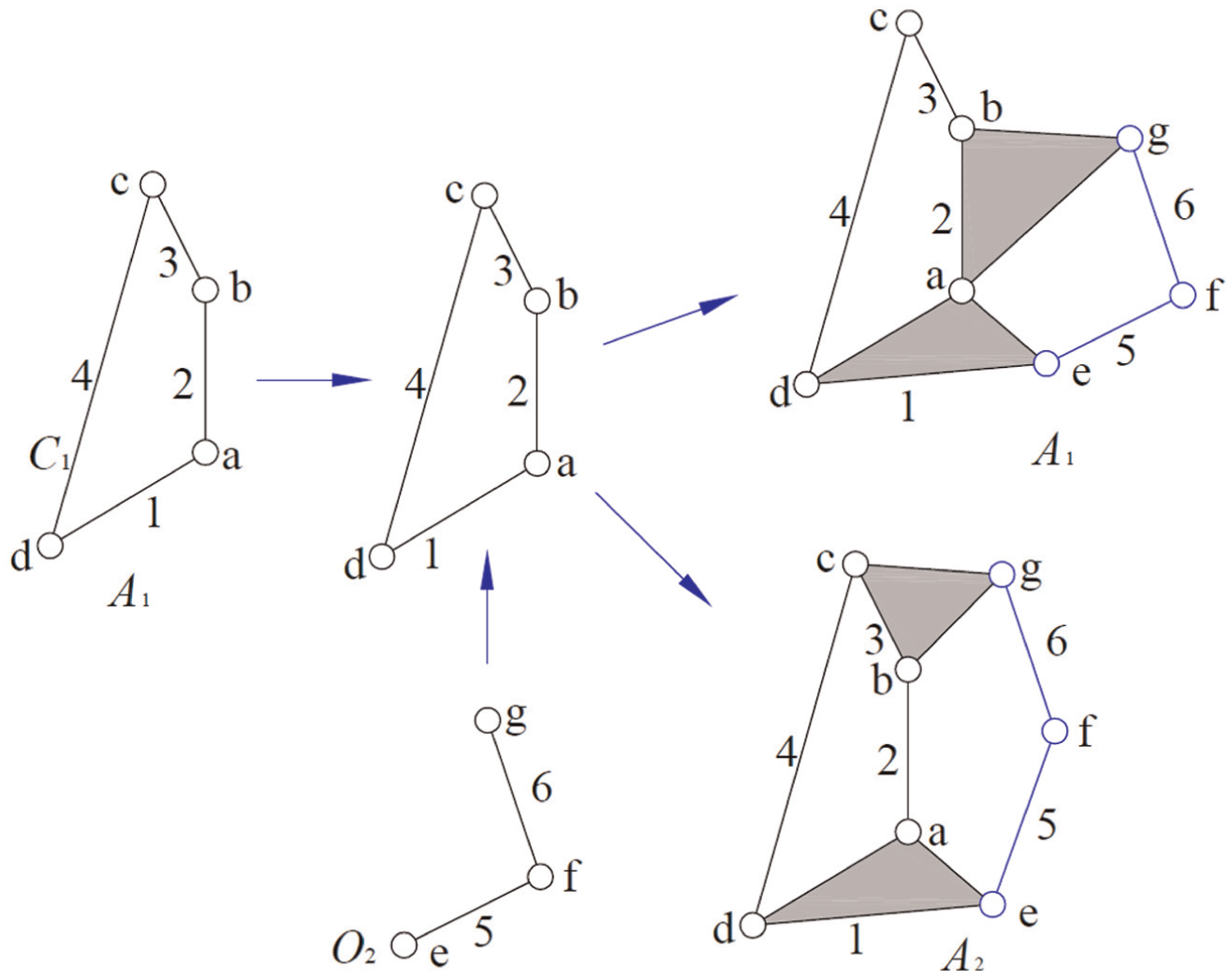
An IM of PSJKC with independent loops D can be formed by subsequently adding Oj (j = 2, …, D) to a basic C1. 14 For example, the process to form an IM of 10-link 1-DOF PSJKC with independent loops D = 4 as shown in Figure 2, the first step is to choose C1(1-a-2-b-3-c-4-d) to form the kinematic chain IM A(4 × 4) with one independent loop; after that, both ends of the O2(e-5-f-6-g) are added to link 1 and 3 to form the kinematic chain IM A(6 × 7); then both ends of the O3(h-7-i-8-j) are added to link 3 and 6 to form the kinematic chain IM A(8 × 10); and finally, both ends of the O4(k-9-l-10-m) are added to link 5 and 8 to form the kinematic chain IM A(10 × 13), which meets the requirements. The corresponding IM A(10 × 13) can be obtained as follows

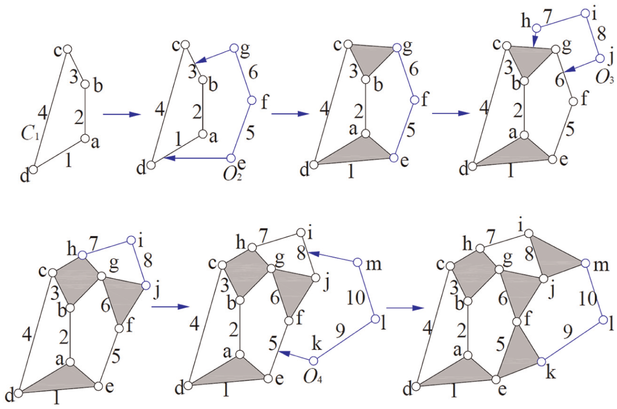
The process to form a 10-link 1-DOF PSJKC IM.
Link-joint distribution sets
Supposed that a PSJKC has independent loops D, the number of links and joints [(m1, n1), (m2, n2), …, (mD, nD)] of the C1, O2, …, OD are determined in the following measures. At the beginning, in all loops of the kinematic chain, choose the one with the minimum number of links as the first independent loop. So the number (m1, n1) of C1 is determined. Then from those remaining O2, O3, …, OD constructing the second independent loop, which still contains the minimum number of links, the number (m2, n2) of the second O2 is obtained. By this logo, for the remaining Oj, Oj + 1, …, OD constructing the jth independent loop, which contains the minimum number of links, the number (mj, nj) of the Oj is obtained. This process can proceed until independent loops D of [(m1, n1), (m2, n2), …, (mD, nD)] for C1, O2, …, OD are constructed.
Synthesize all the IMs of the PSJKCs corresponding to input synthesis task. First, it is very important to determine the number of link-joint distribution sets. For the PSJKCs, if the DOF F and the number of links n are obtained, its independent loops D and the number of joints m can be obtained by


The number of link-joint distribution sets can be obtained as follows:
Step 1. Determine the value of (m1, n1)
For simple joint kinematic chains, notice that the number of link n1 of C1 must be larger than 4 and the first independent loop must be the shortest one. So the following equation can be obtained according to the graph theory

Step 2. Determine the values of (m2, n2)
According to the discussion above on the algorithm to determine the number of links of each independent loop, the addition of second O2 to the first loop C1 should not produce a loop which contains the number of links smaller than that in the first loop, therefore

Step j. Determine the values of (mD, nD) (j = 3, 4, …, (D − 1))
For the same argument in the determination of the values (m2, n2) of O2, the addition of Oj to the existing (j − 1) independent loop kinematic chain should not produce a loop containing the number of links smaller than that in any (j − 1) independent loops. The values of (mj, nj) must be satisfied as follows
Step D. Determine the values of (mD, nD)
As above, the (mD, nD) must be satisfied
So if the parameters F, n of a structural synthesis task are given, it is easy to obtain all the possible distribution sets: [(m1, n1), (m2, n2), …, (mD, nD)] k (k is the number of the joint-link distribution sets).
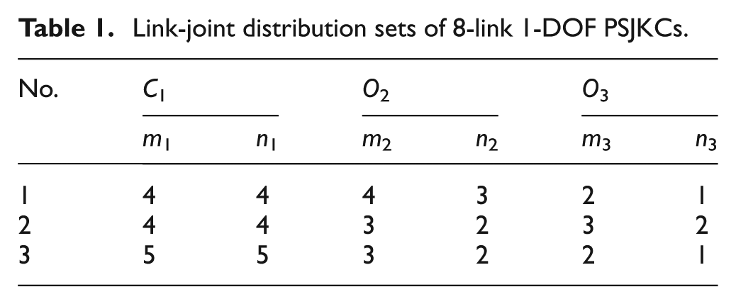
For example, if the parameters of the PSJKCs: F = 1 and n = 8, then we can get that m = 10, D = 3; it is easy to obtain all the corresponding link-joint distribution sets shown in Table 1.
Link-joint distribution sets of 8-link 1-DOF PSJKCs.
Synthesis of the IMs
For the link-joint distribution sets: [(m1, n1), (m2, n2), …, (mD, nD)], we can determine all the IMs of PSJKCs in the following steps:
Step 1. Develop the IM A for the first independent loop. This can be done by the first C1 according to the values (m1, n1). So have

Step 2. Develop the IMs for the two independent loops. This is done by adding the sketched O2 to any group of link-link of the first independent loop from the first group to the last group and it can determine the isomorphic IMs to form all the IMs of 2-th independent loop. First, sketch all the groups of two links If n2 = 0
If n2 ≥ 1


where
Step j. Develop all the IMs for the j independent loops. For the IM of the (j − 1)th independent loop, sketch the Oj and add it to any group of the link-link: If nj = 0
If nj ≥ 1


where
According to Step j, repeat the steps until all the IMs (A1, A2, …, Ae) of D independent loops are obtained. Then, all the IMs are formed corresponding to the link-joint distribution sets.
For example, the link-joint distribution sets:[(4,4); (3,2); (3,2)] of 8-link 1-DOF PSJKCs and the processes to form corresponding IMs can be expressed as follows:
Step 1. Develop the IMs A1 for the first independent loop. This is done by the first C1 according to the number of the link-joint set, (4, 4) meanwhile the IM A can be obtained as shown in Figure 3.
Step 2. Develop the IMs for the second independent loop by the number of the link-joint set (3, 2). This is done by sketching the second O2 and adding it to all groups of the link-link to determine the isomorphic IMs and then got corresponding IMs of two independent loops: A1, A2 which is shown in Figure 4.
Step 3. Develop the IMs for the third independent loop by the number of link-joint set (3, 2). This is done by sketching the second O2 and adding all groups of link-link to two independent loops IMs A1, A2 to determine isomorphic IMs and then got corresponding IMs of three independent loops: A1, A2, …, A13 shown in Figure 5(a) and (b).

Developing the IM for the first independent loop.
Developing the IMs for the second independent loop.

Developing the IMs for the third independent loop. The labels (a,b,c,…,j) are representing the simple joint symbols; the labels (1,2,3,…,8) are representing link symbols.
So for this link-joint distribution set, all 13 types of IMs A1, A2, …, A13 of the 8-link 1-DOF PSJKCs are formed.
SCTG automatic drawing
In this section, the programming for automatically drawing the SCTG of PSJKC by corresponding link-joint IM A is taken into consideration. A direct algorithm is given for automatically drawing the SCTG by IM A in the MATLAB 7.0, which can be expressed as follows:
Step 1. Input the IM
Step 2. Achieve the vertex–vertex AM DA corresponding to SCTG by IM A, the elements of (AM) DA are defined as follows

where if i = j, then bij = 0; if i ≠ j and the vertices i and j are adjacent, then bij = 1, otherwise bij = 0.
Step 3. Obtain the characteristic loop (CL) of SCTG by (AM) DA. As we know, in the SCTG of a PSJKC, the number of independent loops D = m − n + 1, and the total number of its loops is T = 2 D − 1 at most. Try to find the loop which goes through all the vertices whose vertex degrees are more than 3. It contains largest number of vertices in a SCTG and this kind loop is called CL of a kinematic chain. Plenty of PSJKCs have shown that there always exist a few elements of CL, or only one.
Here, a direct algorithm is given to search for CL by the (AM) DA of a double-color topological graph (DCTG), which can be expressed as follows:
Step 3.1. Try to find all the permutation and combination of any two adjacency vertices of (AM) DA: [(v11, v12), (v21, v22), …, (vi1, vi2)].
Step 3.2. For the first combination (v11, v12), use the depth-first-traversal method to form a recursive program to search all the roads from v11 to v12 for all the loops passing the two root vertices (v11, v12).
Step 3.3. Increase i by 1 and repeat Step 3.2 to find loops passing the two root vertices (vi1, vi2). Link them until the last combination of two adjacency vertices is processed to get all the loops [L1, L2, …, LT] of the DCTG.
Step 3.4. Find the CL by choosing the loops which both past all the vertices whose vertex degree is more than 3 and contain the largest number of vertices from the all loops [L1, L2, …, LT]. Such CLs are generally only a few, or even one.
Step 4. Automatically drawing the SCTG by AM DA and CL. It is known that the SCTG can be drawn in many different ways. And the characteristic graph of a non-fractionated graph is gotten in the following steps:
Step 4.1. Draw the CL as the outmost loop in the form of a sharing circle. Specific drawing method can be expressed as follows: If the CL has n1 vertices, draw a circle whose center is (0, 0) and radius is R = 5. Then its perimeter is divided into n1 average parts by vertices. According to the coordinate formula of this circle to obtain the coordinates of each vertex on the CL, draw the vertices of the CL ordered by vertex coordinates.
Step 4.2. Draw remaining vertices inside the CL on the sub simple chains. Specific drawing way can be expressed as follows: first, based on the CL and DA, find out all the sub simple chains (SSC1, SSC2, …, SSCD−1) on which both the start and end vertices are by the depth-first-traversal method. Second, draw a line by both start and end vertices to from a corresponding sub simple chain. If a sub simple chain has n2 vertices, the line can be divided equally into (n2+1) segments to obtain the coordinates of each vertex on this sub simple chain; do just link this above until all the sub simple chains and vertices are determined. If the coordinates of vertices are same, adjust the corresponding coordinates of relative vertices until all the vertices do not coincide. Finally, draw all the vertices in corresponding sub simple chains by the order of coordinates.
Step 4.3. Set corresponding color and label of each vertex in SCTG by DA. The rule to determine the color of each vertex can be expressed as follows: draw the vertices in dark green. The label of each vertex can be determined according to the ranks of DA, where the link vertices are labeled by the ordered number: (1, 2, 3, …, n).
For example, the process to generate SCTG of a PSJKC as shown in Figure 1(a) can be expressed as follows:
Step 1. Input the IM A of the PSJKC.
Step 2. Obtain the vertex–vertex AM DA of the SCTG by IM A as follows
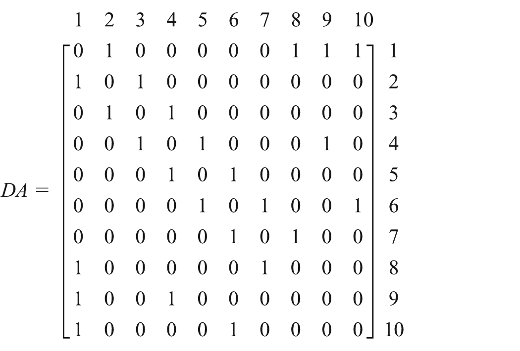
Step 3. Obtain the CL corresponding to SCTG by (AM) DA as follows: (1-2-3-4-5-6-7-8).
Step 4. Automatically draw the SCTG by (AM) DA and CL.
Step 4.1. Draw CL as the outmost loop in the form of a sharing circle. The CL is (1-2-3-4-5-6-7-8) and it has eight vertices. Then draw a circle whose center is (0, 0) and radius is R = 5, then divide its perimeter into eight average parts by vertices and obtain the coordinates of each vertex as follows: [(x1, y1), (x2, y2), …, (x7, y7), (x8, y8)]; finally, draw all eight vertices in order of coordinates.
Step 4.2. Depict the remaining vertices inside the CL on the sub simple chains. Based on the CL and DA, find out all the sub simple chains as follows: SSC1 {1-9-4}, SSC2{1-10-6} and the coordinates of each vertex can be got as follows: [(x9, y9); (x10, y10)]. Then draw two lines by [(x1, y1), (x4, y4)] and [(x1, y1), (x6, y6)] while link the two vertices by each vertex coordinate [(x9, y9); (x10, y10)].
Step 4.3. Define color and label of each vertex in the SCTG from the DA. The SCTG can be drawn automatically, which is shown in Figure 6.

Automatically drawn SCTG of a 10-link 1-DOF PSJKC.
For example, the 16-link 1-DOF PSJKC is shown in Figure 7(a) and its automatically drawn SCTG can be obtained as shown in Figure 7(b).

A 16-link 1-DOF PSJKC and its automatically drawn SCTG. The labels (a,b,c,…,t) are representing the simple joint symbols; the labels (1,2,3,…,16) are representing link symbols.
Automatic topological structural synthesis algorithm
A general algorithm is given for automatic topological structural synthesis of PSJKCs. If the number of links n and DOF F are specified, all possible topological structure of PSJKCs can be automatically synthesized, which can be expressed as follows:
Step 1. Input the parameter value: n and F to obtain the value of independent loops D and the number of revolute joints m. Then, according to the previous discussion, calculate the link-joint distribution set denoted by: [(m1, n1), (m2, n2), …, (mD, nD)] k (k is the number of the joint-link distribution sets).
Step 2. When k = 1, for the first distribution set: [(m1, n1), (m2, n2), …, (mD, nD)] k , we can get all the corresponding IMs of PSJKCs: (A1, A2, …, Ae).
Step 3. Increase k by 1 and repeating Step 2 until the last distribution set of k is processed. Then determine the isomorphic kinematic chains and immovable kinematic chains27,31,35 generated from Step 2 to get all the corresponding IMs: (A1, A2, …, Ab) (b is the number of the PSJKCs of synthesis task).
Step 4. Use the link-joint IMs: (A1, A2, …, Ab) to automatically draw corresponding SCTG of each PSJKC one by one.
In this article, the general algorithm for automatic topological structural synthesis of PSJKC with independent loops D is programmed by MATLAB 7.0. By this algorithm, the topological structure of PSJKC with specified DOF F and the number of links n can be synthesized in batch.
Example 1
For the automatic topological structural synthesis of 8-link 1-DOF PSJKCs, all the 16 structural types of corresponding SCTGs can be obtained, shown in Figure 8.
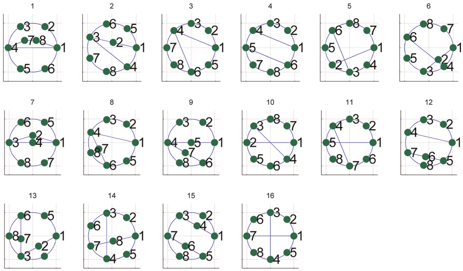
Automatic synthesis of 16 types of 8-link 1-DOF PSJKCs.
Example 2
For the automatic topological structural synthesis of 9-link 2-DOF PSJKCs, all the 40 structural types of SCTGs can be obtained. Among them, the corresponding 24 structural types are shown in Figure 9.
Automatic synthesis of 24 types of 9-link 2-DOF PSJKCs.
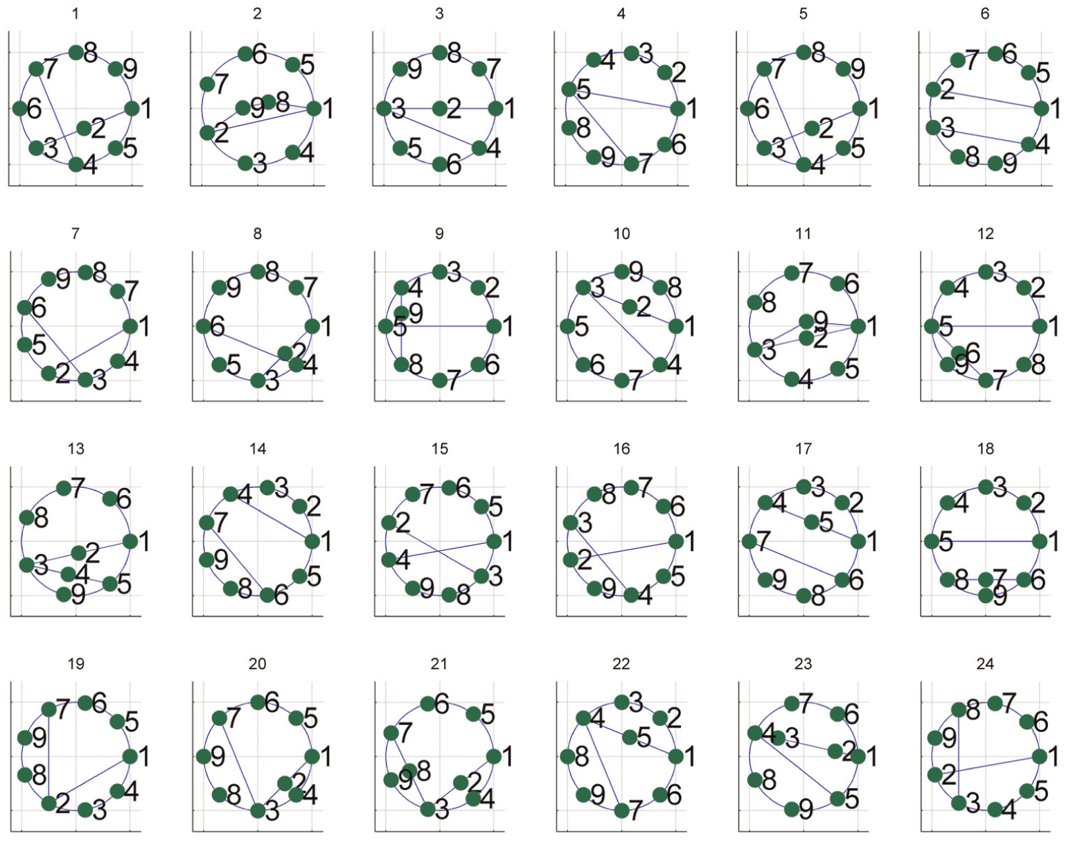
Example 3
For the automatic topological structural synthesis of 10-link 1-DOF PSJKCs, all the 230 structural types of SCTGs can be obtained, among which the corresponding 24 structural types are depicted in Figure 10.

Automatic synthesis of 24 types of 10-link 1-DOF PSJKCs.
As shown in the example above, we can get the desired kinematic chains by this useful algorithm. As the number of links increases, a large number of isomorphic types will be produced in the synthesis process of PSJKCs, which will reduce the overall efficiency of this algorithm. And the efficiency is high for the kinematic chain within 14 links. As for the PSJKCs with links n = 16, the algorithm efficiency can basically satisfy the demand of the mechanism innovation design.
Conclusion
In this article, an automatic topological structural synthesis algorithm has been proposed for the PSJKCs:
Based on the IM described, the PSJKCs with independent loops D can be formed by subsequently adding single open chain Oj (j = 2, …, D) to a basic C1.
An algorithm for automatically drawing SCTG of the PSJKC by the IM is presented. By this algorithm, all the topological structures of PSJKCs can be automatically drawn, which makes the conceptual design of mechanical products more possible.
By the general algorithm for automatic topological structural synthesis of PSJKCs with independent loops D, if the DOF F and the number of links n are specified, all corresponding topological structures of PSJKCs can be synthesized in batch.
Footnotes
Appendix 1
Academic Editor: Yangmin Li
Declaration of conflicting interests
The author(s) declared no potential conflicts of interest with respect to the research, authorship, and/or publication of this article.
Funding
The author(s) disclosed receipt of the following financial support for the research, authorship, and/or publication of this article: This work is supported by the Science and Technology Project of Quanzhou City (2014G48) and (G20140047).