
Abstract
A novel uncoupled and isotropic 2-degree-of-freedom parallel mechanism is presented in this article. The parallel mechanism consists of two kinematic chains: R-4R-R kinematic structure and R-R-P-R-R kinematic structure. The x-axis and y-axis projective angles of the output linkages can be actuated by the corresponding motor mounted on the fixed base. Forward kinematic, inverse kinematic, uncoupled, and isotropic characteristics of the parallel mechanism are analyzed. Singularity analysis and workspace analysis are achieved. The uncoupled and isotropic architecture of the parallel mechanism has some merits such as the larger workspace, a simple mathematical treatment, an easy control, high stiffness, and dexterity. The parallel mechanism can be applied in fields that require aiming at subjects, such as the use of machining tools, radar scanners, telescopes, cameras, satellite solar arrays, the human wrist, and minimally invasive surgery.
Introduction
The parallel mechanism (PM) with high accuracy, good dynamic performance, large load-to-weight ratio, considerable stiffness, low inertia, and accumulative error has attracted more and more attention than the serial counterpart and is widely used in fields of precision parallel machine, high-speed robot, heavy load platforms, precise positioning manipulator, medical robot, and so on. The PM comprises a moving platform, a fixed base, and several kinematic chains, and the motors are mounted on or near the fixed base, which is contributed to reduce the inertia of the PM.
In the past two decades, PMs with fewer than 6-degree of freedom (6-DoF) have drawn some attention. In the less-DoF PMs, 2-DoF PMs have attracted researchers’ attention and have opened new horizons for robotic designers. Chung and Lee 1 designed a new 2-DoF PM using a pantograph mechanism to improve kinematic performance and achieve static balance; at the same time, this PM no longer suffers from the singular configuration that occurs inside workspace. Zhang and Zhang 2 presented a novel 2-DoF PM with three legs, which is used for vehicle driving simulators, and the proposed mechanism has a very simple structure and low cost and can realize two rotations in space. Zhu and Dou 3 optimized 2-DoF 3-RRR PM with actuation redundancy with the consideration of the global conditioning index, the global velocity index, and the global stiffness index. Liu et al. 4 presented a design approach utilizing a performance chart to address the optimal kinematic design of the PRRRP 2-DoF PM. Huang et al.5,6 proposed a hybrid method for the optimum kinematic design of a 2-DoF parallel manipulator and designed a 2-DoF translational parallel robot for pick-and-place operation. Li and Xu 7 proposed a 2-DoF compliant parallel micromanipulator utilizing flexure hinge for two-dimensional nanomanipulation, and kinematic optimization of the design parameters was performed to achieve a maximum workspace subjected to the given dexterity index. Kong8,9 presented a 2-DoF RR-RRR-RRR spherical parallel manipulator as wrists or hip joints of humanoid robots and a special 2-DoF 5R spherical manipulator. Wu et al.10,11 designed a novel 2-DoF translational manipulator which was incorporated into a 5-DoF hybrid machine tool and was optimized by minimizing a global, comprehensive conditioning index, then the counterweight mode was optimized by minimizing the sum of mean square value of actuator forces. 12 Lee et al. 13 presented a 2-DoF planar PM with two linear actuators; the number of this PM is dependent on a passive constraining leg connecting the base and the platform, and the optimization of this PM is performed considering its dexterity and stiffness. However, the kinematic of all 2-DoF PMs mentioned above is not decoupled, uncoupled, or isotropic. Strong kinematic coupling of the PMs generally suffers from many difficulties in the path planning, force feedback, and control algorithm. At the same time, some optimizations of the PM have to be applied to achieve the better performance index. So, the PM with the decoupled, uncoupled, or even fully isotropic is very appealing and will be widely applied.
Numerous relative research activities about the PM with the decoupled, uncoupled, or even fully isotropic have been performed in the academic community for many years. For example, a novel fully decoupled 2-DoF parallel wrist 14 consisting of two interconnected slider-crank linkages was proposed by Carricato. A family of novel 2-DoF rotational decoupled PMs was presented by Zeng et al., 15 the basic characteristic of which is that the moving platform and the fixed base of the PMs are connected by three kinematic chains. A fully decoupled 2-DoF spherical PM designed based on the spherical mechanism called hemisphere was put forward by Li et al. 16 A 2-DoF decoupled spherical PM with a 1/4 circular branch chain and a 7R + R branch chain was designed by Zheng et al. 17 Fully isotropic over-constrained parallel wrists with 2-DoF based on the theory of linear transformation were developed by G Gogu. 18 In the less-DoF PMs other than 2-DoF PMs, some decoupled, uncoupled, and isotropic PMs have been introduced, such as Pantopteron PM 19 which is similar to the Tripteron for Pick-and-Place application, due to the use of three pantograph linkages, the moving platform of the pantopteron moves many times faster than that of the tripteron. A 3-DoF translational PM 20 with a PUPR kinematic chain and the actuated motions being orthogonal provides a very simplified kinematic analysis with fully decoupled input–output linear equations, absence of translational singularities, and isotropy. A 4-DoF PM 21 used in minimally invasive surgery (MIS) is full decoupled PM. A 3-DoF PM called R-CUBE 22 consisting of only revolute joints is uncoupled. A 3-DoF spatial PM 23 with three different kinematic chains is uncoupled and isotropic after optimization design. A 4-DoF fully isotropic PM is used for Schoenflies motion. 24 The less-DoF PMs other than 2-DoF PMs mentioned above provide some advantages, such as the simplified kinematic analysis, ease of determining the workspace, and singularities existing only at the edge of the manipulators workspace. It is great significance to make effort on the decoupled, uncoupled, and isotropic PMs. So far, only one of the 2-DoF PMs is isotropic. However, this 2-DoF PM 18 is over constrained. There is no 2-DoF PM that is uncoupled and isotropic without being over-constrained reported before.
The contribution and novelty of this article is to present a novel uncoupled and fully isotropic 2-DoF PM that is not over constrained. The novel 2-DoF PM is suitable for some applications in which the object to be oriented is axial-symmetrical. Such as, the novel 2-DoF PM is applied to orient a telescope, radar scanner, camera, satellite solar array in space, and surgical instrument in MIS. The merits of this uncoupled and fully isotropic 2-DoF PM that is not over constrained for the above applications include the following: (1) easy forward and inverse kinematic model calculation; (2) simple control algorithm because each DoF is actuated by one motor; (3) kinematic manipulability ellipsoid, dynamic manipulability ellipsoid, stiffness manipulability ellipsoid, and manipulating force ellipsoid becoming a circle; (4) large workspace approximating a hemisphere; (5) no singularities in the workspace except the boundary of a hemisphere; (6) achieving important energy savings due to the fact that for a unidirectional motion only one works as in serial manipulators; (7) robustness to the machining errors and assembly errors; (8) no production of internal stress; and (9) high mechanical efficiency. The only one drawback of this PM without over constrained is that the stiffness is lower than the counterpart of the over-constrained PM, but the stiffness of this PM without over constrained is much larger than the counterpart of the serial mechanism.
The article is organized as follows: a brief geometric description and the mobility analysis of the PM are introduced in section “Description of the PM and its mobility analysis.” Forward kinematic, inverse kinematic, uncoupled, and isotropic characteristics of the PM are analyzed in section “Forward kinematic, inverse kinematic, uncoupled, and isotropic characteristic analysis of the PM.” Singularity analysis of the PM is achieved in section “Singularity analysis of the PM.” The workspace of the PM is dealt with in section “Workspace analysis of the PM.” The potential application of the PM is briefly described; the prototype of the PM and the corresponding workspace are given in section “Some applications of the PM.” The conclusions are drawn in section “Conclusion.”
Description of the PM and its mobility analysis
The schematic structure of the new 2-DoF PM is shown in Figure 1; the moving platform is connected with the fixed base by virtue of two different kinematic chains: the first kinematic chain consists of two revolute joints and a 4R planar closed loop (
The axes of the R1 and R3 joints are coplanar and perpendicular to each other.
The 4R closed loop is parallelogram and is mounted on the linkage connecting with the output axis of the R1 joint.
The intersection of R1 axis and R3 axis coincides with the counterpart of the link 1 and the link 5.
The first condition is applied to guarantee two rotational outputs of the moving platform to be uncoupled. The second condition is used to guarantee the link 3 be parallel with the link 1. The conditions (1)–(3) are achieved to rotate around the fixed point.

The schematic structure of the proposed 2-DoF PM.
According to the general knowledge, the 4R planar closed loop shown in Figure 1, also called a planar parallelogram, has only one translational DoF. Hence, the 4R planar closed loop is regarded as 1-DoF translational pair. The PM has two different kinematic chains: the first kinematic chain has two links and three joints and the second kinematic chain has four links and five joints, and there is no local DoF or redundant constraint DoF. Thus, the DoF of the PM is calculated by equation (1), 25 and the PM has two rotational DoFs

where M represents the DoF of the PM, n and g denote the number of links and joints, respectively, fi represents the DoF associated with the ith joint, and
Forward kinematic, inverse kinematic, uncoupled, and isotropic characteristic analysis of the PM
Referring to Figure 1, a is the length between the axis of the 4R4 joint and the fixed point o0, b and c are the lengths of the link 1 and 2, respectively, d is the length between the fixed joint o0 and the link 6, e is the length of the link 6, g is the length between the axis of the R4 joint and the fixed point o0, l is the length between the axis of the R4 joint and the counterpart of the R5 joint at the initial state, and α represents the angle between the P1 joint axis and the plumb line at the initial state. q11 and q21 are defined as the input variables of the actuated joints R1 and R3, respectively. q12 and q13 denote the joint variables of the 4R and R2 pairs, respectively. q22, q23, q24, and q25 denote the joint variables of the R4, P1, R5, and R6 pairs, respectively.
The naming convention and the zero configuration are shown in Figure 1. To construct the twists for the joints of the first kinematic chain, note that

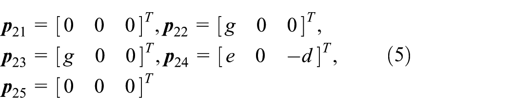
and the axis points of the first kinematic chain are chosen as

To build the twists for the joints of the second kinematic chain, note that

and the axis points of the second kinematic chain are chosen as
This yields twists for a revolute joint

This yields twists for a prismatic joint
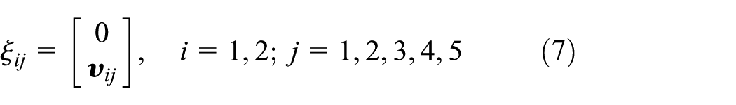
where
And the zero configuration

The forward kinematic map of the first kinematic chain has the form
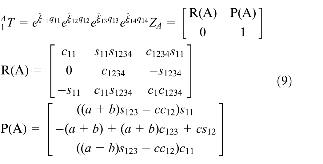

where s1i = sin(q1i), c1i = cos(q1i), s1ijk = sin(q1i + q1j + q1k), and c1ijk = cos(q1i + q1j + q1k); i = 1, 2, 3, j = 1, 2, 3, and k = 1, 2, 3, 4.
Because there is a planar parallelogram in the first kinematic chain, the relationship between q12 and q13 can be obtained as follows

Equation (9) can be rewritten as follows

Equation (10) can be rewritten as follows

The forward kinematic map of the second kinematic chain has the form
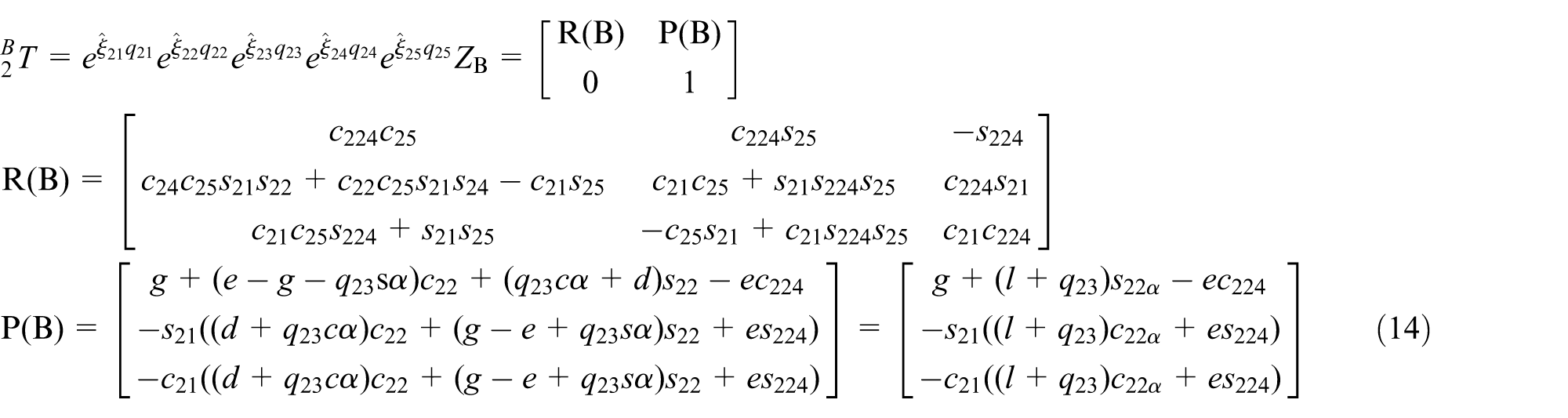

where s2i = sin(q2i), c2i = cos(q2i), s2ij = sin(q2i + q2j), c2ij = cos(q2i + q2j), cα = cos(α), sα = sin(α), s2iα = sin(q2i − α), and c2iα = cos(q2i − α); i = 1, 2, 3, 4, 5 and j = 1, 2, 3, 4, 5.
Three points o0, A, and B are fixed on the axis of the link 5, which are collinear, equation (16) can be given by

where λ∈R and λ≠0.
Based on equations (12)–(16), we can obtain
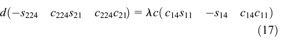
Based on the equation (17), we can obtain
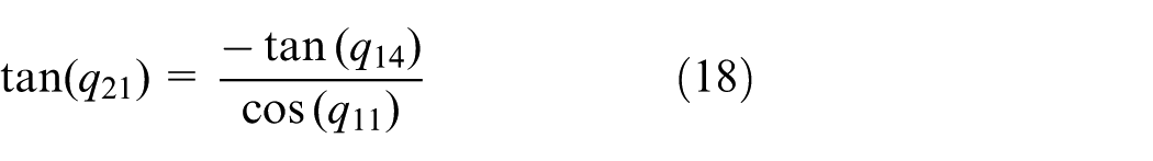

Based on equation (19), we obtain

Equation (21) can be drawn by substituting tan(q21) from equation (18) into equation (20)

Equation (19) can be rewritten as

The point o0 is the fixed point.
Referring to Figure 2, the w-axis is defined as axis of the moving platform which coincides with axis of the joint R6. The x-axis and y-axis projective angles θ1 and θ2 can be described using the concept of projective angles and are defined as the output variables of the moving platform, θ1 is measured from the x-axis to the projection of the w-axis on the xoz-plane, and θ2 is measured from the y-axis to the projection of the w-axis on the yoz-plane, θ1∈ [−π, π], θ2∈ [−π, π]. The counter-clockwise rotation is defined as the positive direction of the angle. The situation shown in Figure 1 is θ1 = 0.5π and θ2 = 0.5π.
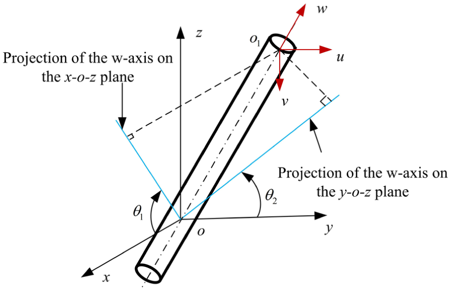
The projective displacement representation of the two revolute DoF motions.
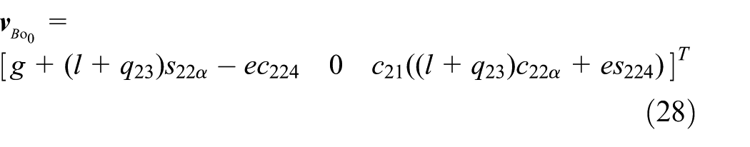
The projection vector

The vectors of the x0 axis and y0 axis are expressed as

The angle between

When

When

When
The projection vector
The angle between

When

When

When

When

All singular configurations are
When

When

When


The conventional Jacobian matrix J is a diagonal matrix, and the uncoupled motion is realized. Because the condition number of the kinematic Jacobian is 1, the PM is isotropic in the whole workspace.
Singularity analysis of the PM
In singular configurations, the manipulators will gain or lose one or more instantaneous DoFs, which will lead to a loss of the controllability and motion stability, lower stiffness, or even damage to the instrument. Thus, the singularity analysis is indispensable in the mechanism and control design stage and has been paid more attention.
Singularity analysis methods based solely on the Jacobian matrix derived from the input–output velocity map is valid for general-purpose planar or spatial parallel PMs, for which the DoF of each serial kinematic chain is equal to the counterpart of the end-effector, but it may fail to detect certain singularities in the limited-DoF PMs.26–29 A new methodology for the Jacobian analysis of limited-DoF PMs was proposed to solve this problem by Joshi and Tsai, 30 and the Jacobian matrix derived by virtue of this method provides the information about both architecture and constraint singularities. This method is applied to analyze the singularity configurations of the proposed 2-DoF PM. However, this method does not give the information about the limb singularity. 31 The limb singularity is similar to the singularity of a serial manipulator. If a limb singularity occurs, the limb will lose one DoF instantaneously. The main cause of limb singularity is due to linear dependence of the joint screws, it means that the limb increases one constraint screw instantaneously. In the derivation process of the singularity analysis, if the limb increases one constraint screw instantaneously at one configuration, this configuration is regarded as the limb singularity.
In order to analyze the singularity of the proposed 2-DoF PM, an instantaneous reference frame with its origin located at point o2 and the axes x2, y2, and z2 parallel to the axes x0, y0, and z0 of the o0-x0y0z0 frame is defined. All joint screws are defined with respect to this instantaneous reference frame. Figure 1 shows the proposed 2-DoF PM which consists of a moving platform, a fixed base, and two kinematic chains. The first kinematic chain connects the fixed base to the moving platform by a revolute joint followed by a 4R closed loop and another revolute joint shown in Figure 3. The 4R closed loop is parallelogram, which can be regarded as the PM. Link 1 and link 3 are chosen as the fixed base and the moving platform, link 2 and link 4 are regarded as the kinematic chains. The instantaneous twist of the link 2 can be written as


Schematic of the first kinematic chain.
The instantaneous twist of the link 4 can be written as
The constraint reciprocal screw system of the link 2 can be obtained as
The constraint reciprocal screw system of the link 4 can be obtained as

The equivalent constraint reciprocal screw system and kinematic screw of the 4R closed loop can be obtained as

Let the DoF associated with all the joints of the kinematic chain be defined as the connectivity. The connectivity of the first kinematic chain is equal to 3. Therefore, for the first kinematic chain, the instantaneous twist, $ p , of the moving platform can be written as a linear combination of three instantaneous twists

where
The second kinematic chain connects the fixed base to the moving platform by a revolute joint followed by a revolute joint, a prismatic joint, a revolute joint, and another revolute joint as shown in Figure 4. The connectivity of the second kinematic chain is equal to 5. Therefore, for the second kinematic chain, the instantaneous twist of the second kinematic chain, $ p , of the moving platform can be expressed as a linear combination of five instantaneous twists

where


Schematic of the second kinematic chain.
Those screws that are reciprocal to all the joint screws of the first kinematic chain form a 3-system. Hence, those screws which are reciprocal to all the joint screws of the first kinematic chain can be identified. These reciprocal screws are denoted as

where
Those screws that are reciprocal to all the joint screws of the second kinematic chain form a 1-system. Hence, one screw which is reciprocal to all the joint screws of the second kinematic chain can be identified. This reciprocal screw is denoted as

where
Equations (45) and (46) can be written in matrix form as

where

Equation (47) characterizes the constraints imposed by the joints.
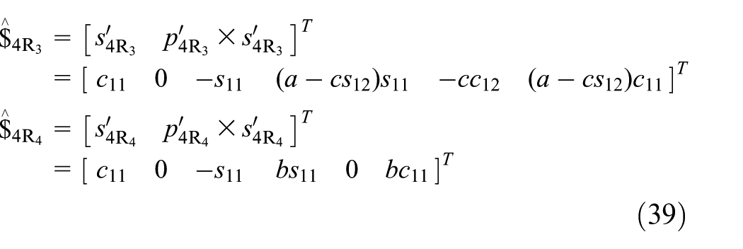
Next, the actuator of each kinematic chain is locked; the reciprocal screws for the first kinematic chain form a 2-system. One additional basis screw
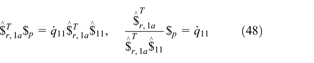
where
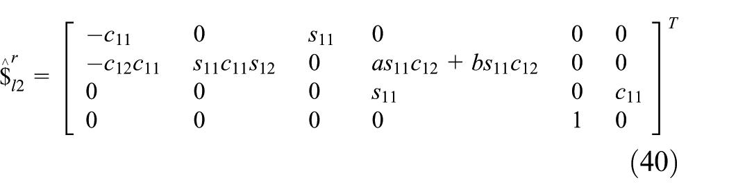
The reciprocal screws for the second kinematic chain form a 4-system. One additional basis screw

where
Equations (48) and (49) can be written in matrix form as

where
Equation (50) denotes the actuation effect.
Complementing equations (50) with (47) yields

where
Referring to Joshi and Tsai, 30 constraint singularity occurs when Jc loses its rank, whereas architecture singularity occurs when det(J) = 0 but Jc has a full rank.
The determinant of J is given by

The singularity analysis is discussed as follows:
When
When

Taking the orthogonal product of both sides of equation (44) with

3. When
4. When
When

Because

Based on above singularity analysis, the singular configurations are given by
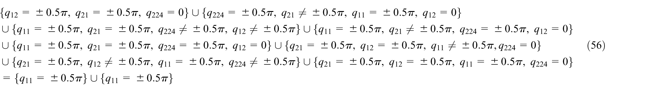
The singular configurations are
In order to explain constraint screw clearly, Figure 5 is given which contains all the constraint screws acted on the moving platform in general configuration. The conclusion that the four constraint screws are independent in general configuration in Figure 5 can be drawn. All the constraint screws acting on the moving platform in general configuration is written as


All the constraint screws acted on the moving platform.
Workspace analysis of the PM
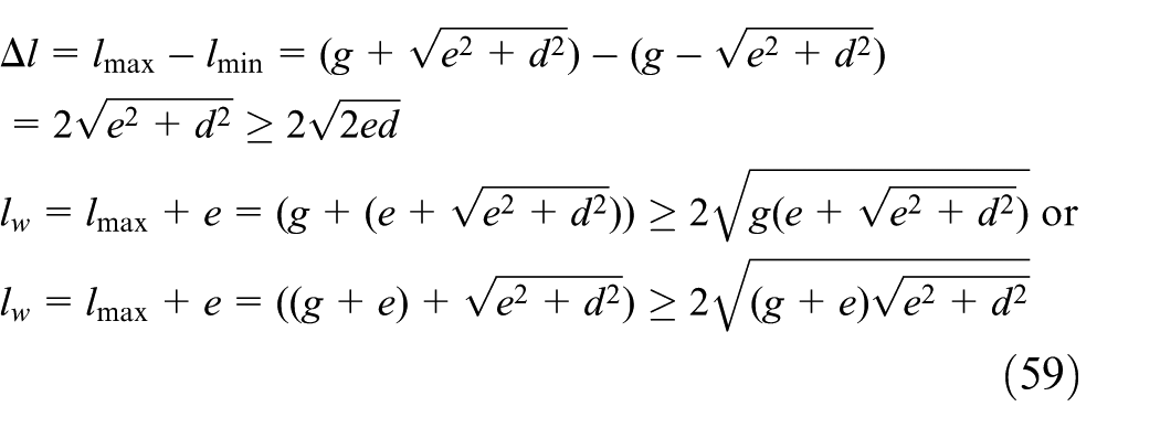
The prismatic joint is used in the second kinematic chain. Figure 6 shows the maximum length and the minimum length of the prismatic joint. In order to make PM compact, two conditions should be met: (1) the stroke

This yields
When

When

When

Two different extension length of the prismatic joint: (a) the maximum extension length of the prismatic joint and (b) the minimum extension length of the prismatic joint.
There is a 4R closed loop in the first leg. In order to make the first kinematic chain compact and avoid collision, the 4R closed loop is replaced by the synchronization belt (which is used in section “Some applications of the PM”). The collision only occurs between the link 4 and link 6. The distance between link 4 and link 6 should be larger than r4 + r6 to avoid the collision as shown in Figure 7. The distance between the link 4 and link 6 is expressed by

where p4 and p6 are the arbitrary points of the link 4 and link 6, respectively, r4 and r6 are the radiuses of the link 4 and link 6, respectively.

Schematic diagram of the distance between link 4 and link 6.
When λ > 1, the conditions that lead to collision between link 4 and link 6 is written as
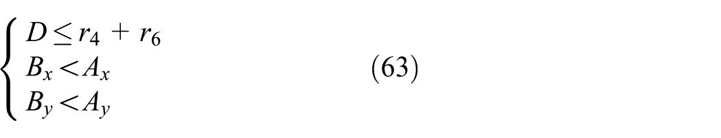
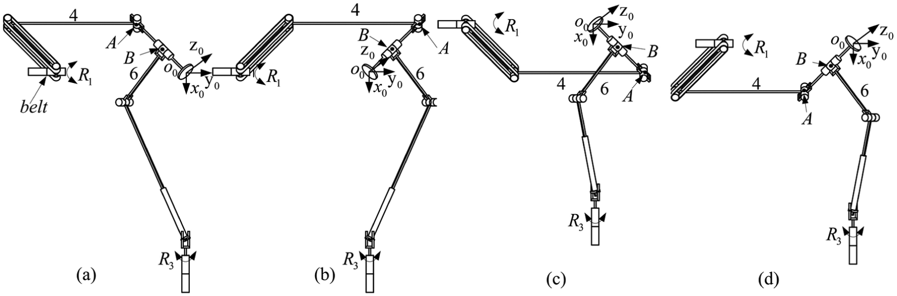
If the conditions that are defined by equation (63) are met, the collision between the link 4 and link 6 occurs, this situation is shown in Figure 8(a). If the condition

The four working modes when
When 0 < λ < 1, the conditions that lead to the collision between link 4 and link 6 is written as

If the conditions that are defined by equation (64) are met, the collision between the link 4 and link 6 occurs; this situation is shown in Figure 9(c). If the condition
The four working modes when
The direction vectors of link 4 and link 6 are written as respectively

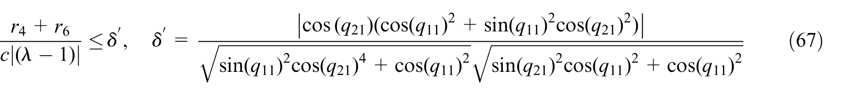
The positions of the A point at the link 4 and the B point at the link 6 can be expressed by equations (12) and (14), respectively. Utilizing equation (62), we can obtain

In order to design the 2-DoF PM to meet the desired workspace, the values of the c, λ, r4, and r6 should be determined to meet the requirement, that is written based on equation (66) as follows

(a) The relationship between δ and the workspace, (b) the relationship between δ and the workspace that meets the conditions defined by equation (63), and (c) the relationship between δ and the workspace that meets the conditions defined by equation (64).
Some applications of the PM
The 2-DoF PM is suitable for many fields in which the object to be oriented is axial-symmetrical and the third rotational DoF of the moving platform is not indispensable, such as machining tool, radar scanner, telescope, camera, and satellite solar array. The computer-aided design (CAD) model of the oriented PM is shown in Figure 11. The equipments mentioned above can be mounted on the moving platform. In order to reduce the collision probability and increase the workspace, the 4R planar closed loop is replaced by the synchronous belt. Extensions 1, 2, 3, and 4 supply four videos showing the oriented PM model when it follows, with harmonic movement, the four trajectories depicted in Figure 12 with a blue solid line, a green blue solid line, a blue dash-dot line, and a green dash-dot line, respectively (Appendix 1). The workspace, simulation path, and singularity configurations of the oriented PM are presented in Figure 12.

CAD model of the oriented PM.

Workspace and singularity of the prototype.
The novel 2-DoF PM adding one translational joint shown in Figure 13 can be used in MIS. The x-axis and y-axis projective angles simulation of the 2-DoF PM without consideration of the one translational joint is presented in Figure 14. Extensions 5 and 6 provide two videos showing the PM model used in MIS when it follows, with harmonic movement, the two trajectories depicted in Figures 14 and 15 with red dotted lines and blue dash-dot line, respectively. The workspace of the PM used in MIS is a cone with a vertex angle of 140° as shown in Figure 15 which is greater than the cone with a vertex angle of 90° and meets the requirement of the MIS. 32 When the endoscope is mounted on the translational platform, the PM can be used to hold the endoscope to provide the surgical environment to monitor in the traditional endoscopic surgery. When an insertable robotic effectors platform (IREP) with integrated stereo vision and surgical intervention tools is fixed on the translational platform, the PM can enlarge the workspace and increase the dexterity of the IREP to accomplish the single port access surgery. When a surgical instrument is mounted on the translational platform, two PMs can achieve MIS with high precision and dexterity due to the PM being uncoupled and isotropic.
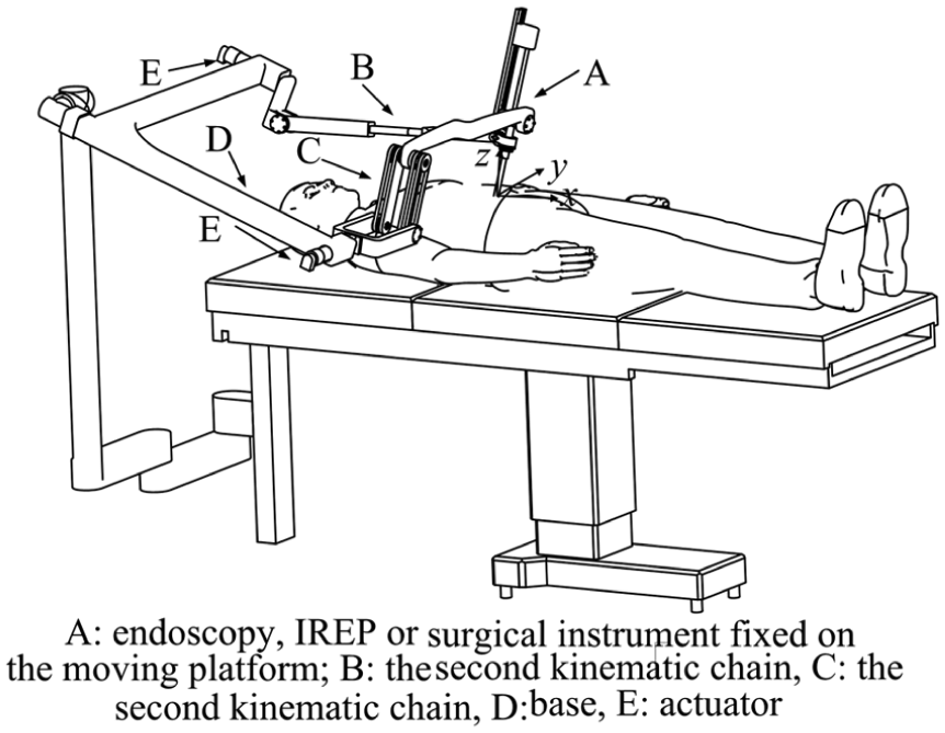
CAD model of the PM used in MIS.

Simulation path and singularity of the 2-DoF PM used in MIS.
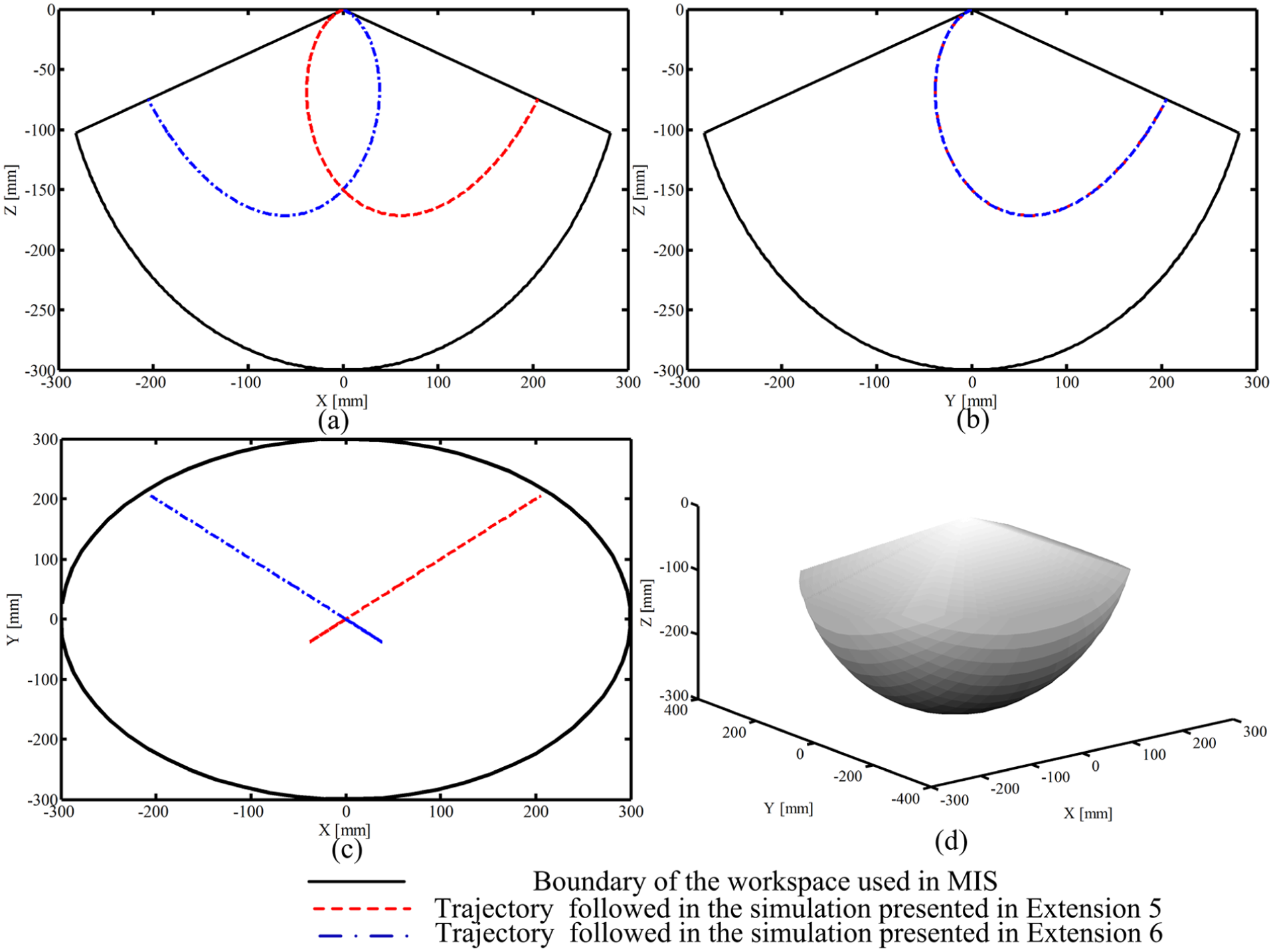
Workspace and simulation trajectory of the prototype: (a) view at the xoz-plane, (b) view at the yoz-plane, (c) view at the xoy-plane, and (d) isometric view.
Conclusion
A new 2-DoF PM with two rotational outputs was proposed in this article. The PM comprises two simple joints, revolute and prismatic joints, without cylindrical or spherical joints; as a result, the cost of manufacturing and assembly are reduced for this PM. A brief geometrical description, the mobility analysis, the analysis of forward and inverse kinematics, and the analysis of uncoupled and isotropic characteristic of the PM were achieved. The singularity analysis and workspace analysis were performed. Because the conventional Jacobian of the PM is an identity 2 × 2 matrix throughout the entire workspace, the PM is an uncoupled and isotropic mechanism, so the trajectory planning and control of the PM is easy to implement. The application fields of this PM are widely discussed. Such a mechanism can be used in a field that requires aiming at a body in space (e.g. machining tool, radar scanner, telescope, camera, and satellite solar array) or rotation about a fixed point (e.g. MIS).
Footnotes
Appendix
Index to multimedia extensions.

| Extension | Type | Description |
|---|---|---|
| 1 | Video | The oriented PM prototype model in motion |
| 2 | Video | The oriented PM prototype model in motion |
| 3 | Video | The oriented PM prototype model in motion |
| 4 | Video | The oriented PM prototype model in motion |
| 5 | Video | The PM prototype model used in MIS in motion |
| 6 | Video | The PM prototype model used in MIS in motion |
PM: parallel mechanism; MIS: minimally invasive surgery.
Academic Editor: Yangmin Li
Declaration of conflicting interests
The author(s) declared no potential conflicts of interest with respect to the research, authorship, and/or publication of this article.
Funding
The author(s) disclosed receipt of the following financial support for the research, authorship, and/or publication of this article: This work is supported, in part, by the National High Technology and Development Program of China (No. SS2012AA041601), National Science Foundation of China (No. 61305139), and Self-Planned Task of State Key Laboratory of Robotics and System (SKLRS201406B, SKLRS201412B, and SKLRS 201501C).