
Abstract
According to the problem that the mathematical model of the fuel supply system of the high-temperature high-speed wind tunnel is hard to be established, this article uses the method which combines the mechanism modeling method and system identification to establish the equivalence mathematical model of the fuel supply system. First, according to the working principle of the system, the original mathematical model of the fuel supply system is established using mechanism modeling method; the characteristics of the system are analyzed, and the unknown parameters and time-varying parameters are ascertained, that is to say, the prior knowledge of the system is obtained. Then, unknown uncertain parameters of the system are estimated using least square method, so the equivalence mathematical model of the fuel supply system can be obtained. The simulation and experimental results show that the mathematical model of the fuel supply system established in this article has high precision and can be used as an actual model in the control of the fuel flow rate.
Keywords
Introduction
Because of air friction, the head temperature of missile or rocket would exceed 1000°C when it is flying in high speed. High-temperature high-speed wind tunnel (HTHSWT) is an experimental equipment, and it is used to achieve the safety test of the specimen of high-speed aircraft. Its work principle is that: takes high-speed air stream as accelerant and aviation kerosene as fuel, and the high-temperature high-speed airflow can be obtained by the combustion, so high-temperature conditions encountered by high-speed aircraft’s specimen during flight can be simulated. A stable temperature field will be formed surrounding the aircraft’s specimen, and the core temperature of the temperature field determined by the fuel flow rate in the case of the airflow is a constant and the fuel is burning up completely. Therefore, the prerequisite for the normal and stable operation of the system is that the precise control of fuel flow rate of the fuel supply system can be achieved. In order to achieve the precise control of the fuel flow rate, a precise mathematical model of the fuel supply system must be established, and the characteristics of the system must be analyzed.
The modeling method of the system mainly includes the mechanism modeling method, the system identification modeling method, and gray-box modeling method. The mechanism modeling method is applied widely in system modeling because it can reflect real situation of the system. Guan et al. 1 established the mathematical model of the hydraulic pipe system using mechanism modeling method, and the control of fluid pressure pulsation was realized using a novel active control method. A computational model of a switch-mode circuit for a virtually variable displacement bidirectional pump/motor was presented by Van de Ven. 2 Steinboeck et al. 3 established a mathematical model of the electro-hydraulic servo valve using mechanism modeling method. However, the mechanism modeling method can only solve the modeling problem of the easy dynamic system and is applied hardly when the dynamic of the system is complicated and the dynamic mechanism is not clear.
The system identification modeling method which uses the input and output of the system data to establish model of the system is also applied widely. It has many advantages, such as it does not need to understand the dynamic mechanism of the system, does not need many mathematical equations to express the dynamic of the system, and has the ability to modify the mathematical model online constantly. Ling et al. 4 obtained a model of the electro-hydraulic actuator system using system identification approach. A mathematical model of electro-hydraulic position servo test bench was obtained based on the system identification approach described by Shao et al. 5 A nonlinear model including dead zone of electro-hydraulic servo system was established based on multi-particle swarm optimization described by Ming et al. 6 However, when the model of a big complicated system needs to be established and the information of sample data is comparably single, modeling accuracy and generalization ability of this method cannot meet the people’s requirements.
The gray-box modeling method is a system modeling method which combines the prior knowledge and the system identification modeling method. The prior knowledge means the parts or the whole mechanism mathematical model of the system. Prior knowledge is introduced into the modeling, and system analysis can not only reduce the optimization efficiency of the modeling process effectively but also solve the problem to some extent that the system identification modeling method is too strict for the sample data. Therefore, the gray-box modeling method is also applied and researched widely. A gray-box identification model of the new type continuous rotary electro-hydraulic servo motor was established by Cao and Ma, 7 and the experimental results showed that the method is effective for the achievement of accurate performance parameters of hydraulic system. Tang et al. 8 put forward a subsystem model-based close-loop gray-box identification method when the model for a hydraulic Stewart platform was established. Shi et al. 9 combined a mechanism model and neural networks to develop a gray-box model and applied it in a model-based fault detection system. Bai et al. 10 used the theory of gray-box modeling to simplify the mathematical model of entrance throttle control system, and the model error caused by empirical value in different conditions of the system was eliminated. The mathematical model of the hydraulic support was established using gray-box identification model described by Li and Zhang. 11
Some parameters, such as pressure loss, are sensitive to the temperature change in the HTHSWT. That means the system has time varying to some extent and cannot use the traditional mechanism modeling method to establish the accurate mathematical model. Therefore, this article used the method which combines the mechanism modeling method and the system identification modeling method to establish the equivalent mathematical model of the system, that is to say, the gray-box modeling method is used to establish the mathematical model of the fuel supply system.
Modeling of system mechanism model
System description
Fuel supply system is a typical fluid conveying system with long pipe. The principle of the system is shown in Figure 1. It can be seen from the figure that the system consists of variable-frequency driver (VFD), fuel tank, three-phase asynchronous motor, fixed volumetric pump, flowmeter, pipeline circuits, controller, and so on. After the start of the system, the operator sends the flow-rate instruction to the controller, then the controller collects the flow-rate signal from the flowmeter, and the control output is obtained by the internal control algorithm; finally, the control output is converted into the standard signal (1–5 V) and controls the variable-frequency motor, so as to achieve the control of fuel flow rate of the system.

The principle of the fuel supply system.
Modeling of the system
It can be seen from the work principle of fuel supply system that the model of the system includes the model of variable-frequency motor, the model of fixed volumetric pump, the model of pipeline circuit, and the model of flowmeter.
The model of variable-frequency motor
The electromagnetic equations which describe the dynamic process of variable-frequency motor are very complicated; generally, there are two approximate models to describe it. One is an approximate model with a constant ratio between voltage and frequency, and the other is nonlinear approximate equations based on the principle of vector control. Generally, the second model is much closer to the real variable-frequency motor model and can reflect the transient process of the startup process. Compared with the dynamic process of hydraulic system, the transient process of motor is too short. Therefore, the electromagnetic torque equation of asynchronous motor can be obtained by ignoring the electromagnetic transient process 12

where
The torque balance equation of the motor shaft can be expressed as 13

where
The model of fixed volumetric pump
The work pressure is lower in the fuel supply system and it is about 1 MPa, but the elastic modulus of fuel liquid is too large and it is about 1000 MPa. Therefore, the flow continuity equation of hydraulic pump can be obtained by ignoring the liquid compressibility. It can be expressed as

where q is the output flow rate of the pump,
The model of pipeline circuit
Because the pipeline circuit from the pump to the nozzle in which the wind tunnel combustor is too long and the system has no significant load, the main load of the system is the pressure loss along the pipeline circuit. Thus, the pressure loss along the pipeline circuit should be considered when the model of pipeline circuit is established. Therefore, this article uses lumped parameter method to establish the model of pipeline circuit, that is to say, takes pipeline circuit as electric circuit and considers that there are fluid resistance, fluid capacitance, and fluid inductance in the pipeline circuit. As seen in Figure 2,

where l is length of the pipeline, d is inner diameter of the pipeline, A is the total sectional area of nozzles,

The lumped parameter model of the pipeline circuit.
Combining equation (1) and equation (4) yields a transfer function between the fuel flow rate q and the VFD input voltage u as follows

where
The model of flowmeter
Because the turbine flowmeter has many advantages, such as higher measurement accuracy and lower price, and applied widely, it is used in fuel supply system. But it also has the disadvantages of general flow integrating instrument, it exists larger inertia and time delay. Therefore, the flowmeter can be considered as a one-order inertial link with pure time delay, and its transfer function can be expressed as

where
Parameter identification of the system
The basic principle of identification
The model established in previous section using the mechanism modeling method is not accurate and some parameters are estimated, such as the damping of fuel and the rotational inertia of the motor shaft. Besides, because the dynamic viscosity coefficient of fuel is sensitive to the temperature change, the transfer function of the system is different at different times of the year. Therefore, in order to meet the control requirements of the system, it is necessary to adjust the controller parameters. In order to establish an accurate mathematical model for the system, this article improved the model using the system identification method. In the identification of the fuel supply system, this article uses the signal from the controller output and the flowmeter output to identify the system using least square method.
The model identification hardware of fuel supply system is shown in Figure 3. It can be seen form Figure 3 that the identification hardware of fuel supply system includes programmable logic controller (PLC), industrial personal computer (IPC), VFD, and flowmeter. Because the computational complexity of the least square method is too large, the IPC just operates calculation and the PLC just collects data. In the system, PLC collects the signal of the control voltage of VFD and the flow-rate signal of the flowmeter in every cycle and sends them to IPC which operates calculation of the identification parameters. The system parameters obtained by identification are mainly used to adjust the proportional integral (PI) parameters of the controller. Because the time-varying parameters in the system are changed slowly, the controller parameters do not need to be changed in a long time and the PLC can collect data along the time. Therefore, the cycle of the system identification can be designed longer and it is about 5–10 min. In this way, not only the tasks of the IPC are reduced but also the problem that the controller parameters are changed too frequent when the identification parameter is at the critical point of adjustment algorithm is avoided.

The hardware of system identification.
In fuel supply system, the input and output signal of system and the identified system can be linked as a forward channel, and the noise is generally existed in the part of signal acquisition of the flowmeter. In the part of controller output, the PLC and VFD have good noise immunity, so the noise effect in this part can be ignored and the system meets the identification conditions.
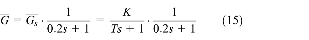
It can be seen from the model which established in previous section that the fuel supply system is an over damping system, the equal transfer function can be expressed as
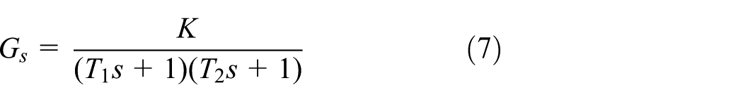
where K is the proportional amplification factor of the system and
Because the transfer function of flowmeter is stable and the accurate data can be obtained by calibrating, the flowmeter is a known link. When PLC collects the data of the flowmeter in industrial field, the signal is easy to be disturbed. Assumed that the interference is a noise signal whose average value is zero and the noise is distributed independently and identically, the magnitude of the noise signal is smaller than the flow-rate signal. Therefore, the model of the system identification can be simplified as the noise model as shown in Figure 4.
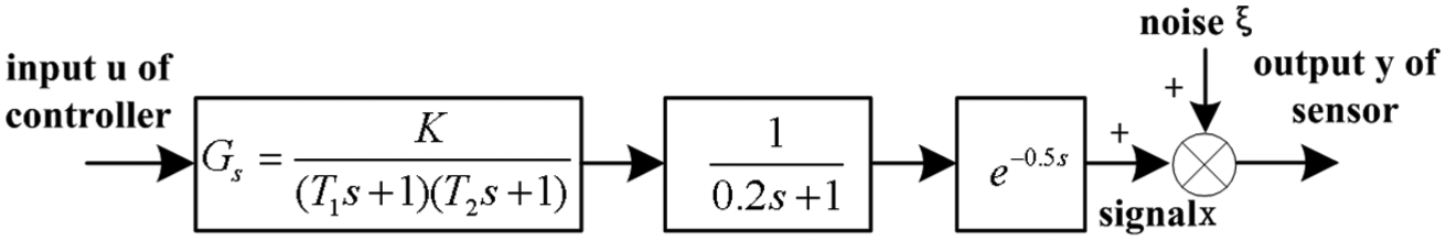
The identification model of fuel supply system.
Because there are effect of sample and hold in controller and sensor, the input u can be seen as several step signals. Since the system meets the linear superposition principle, the output increment of y in every cycle can be obtained by control input in the previous N cycles, where N should meet the conditions: for a step input signal, when the response time is over NT, the y goes stable. The identification method based on input data u and output data y of the system can be obtained by the above conditions.
Realization of the system identification
First, the following variables are defined in the condition of the control cycle 1 s:
Assumed that the unit step response of the fuel supply system is
Define

Assumed that the collected data of flowmeter is
The increments of control variable are
Because of the linear superposition characteristics, the following equation can be obtained
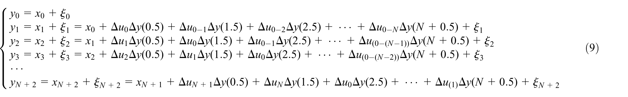
Assumed that

The standard equation of the least square method can be obtained from equation (9)

where
The least square estimated value of the

Because
In fact, the purpose of selecting
In order to choose an appropriate N for the system, the system is analyzed using the prior knowledge in this article. The time-varying parameter that affects the system is the fuel dynamic viscosity
When

When

The step response curves in the two conditions are shown in Figures 5 and 6. From the two figures, it can be seen that the adjust time of system (steady-state value is 98%) is about 5–6 s in the two conditions, so this article chooses N = 5 when the system is identified.
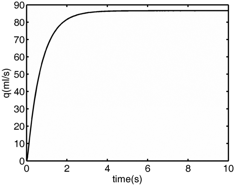
The step response curve of the system when

The step response curve of the system when
From the above data, the main change of the system is the change of K in equation (7), and the change of adjustment time is not big. There is a small time constant link in the system
The physical meaning of the identified variable is that the step response values at time points

After the reverse Laplace transforms for equation (16), the step response can be obtained
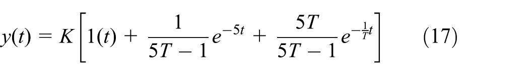
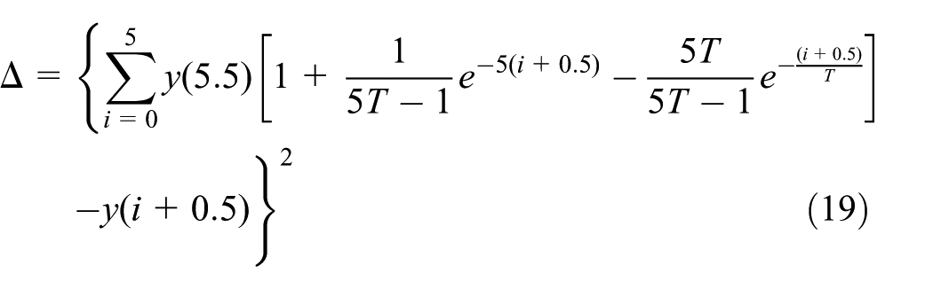
K and T are calculated by least square method, while the change of

T is calculated by least square method, it is the value when equation (19) is the least. The equation (19) is a nonlinear equation which can be solved by Newton iteration method
While the above algorithm can achieve the system identification online, the control characteristics of the fuel supply is that the input of the system is multiple step signals, it makes the input and output of the system often in a stable state, and the stable data will make the
Simulation
The simulation of the parameter identification using the above method was carried out in MATLAB. When simulating, the object

For equation (13), the fuel supply system can be expressed as
In a simulation, the step signal strength is 25 and the noise signal strength is 0.05; first, a group of
Therefore, the identification result can be obtained, it can be expressed as

The step response curve of
The step response curve of

The comparative curve between
Experiment
The experimental equipment
In order to verify the correctness of the model and to realize the control of fuel flow rate, a practical fuel supply system is designed. On this basis, a control system for fuel flow rate is developed based on field PLC and remote IPC. The experimental equipment of the control system is shown in Figure 9, and it consists of four parts. The fuel-pump room consists of fuel tank, motors, pumps, relief valves, and pipelines; it is used to provide fuel for the system. The fuel distribution cabinet consists of solenoid valves, manual valves, and pipelines; it is used to distribute fuel to the combustors of the wind tunnel. The VFD control cabinet consists of VFD and air switch; it is used to drive the variable-frequency motor. The fuel control system consists of field control cabinet and remote control system; it is used to realize the precise control of fuel flow rate. The field control cabinet consists of PLC and its components; the remote control system consists of IPC and control software.

The experimental equipment of the control system: (a) fuel-pump room, (b) fuel distribution cabinet, (c) VFD control cabinet, and (d) fuel control system.
The experimental result
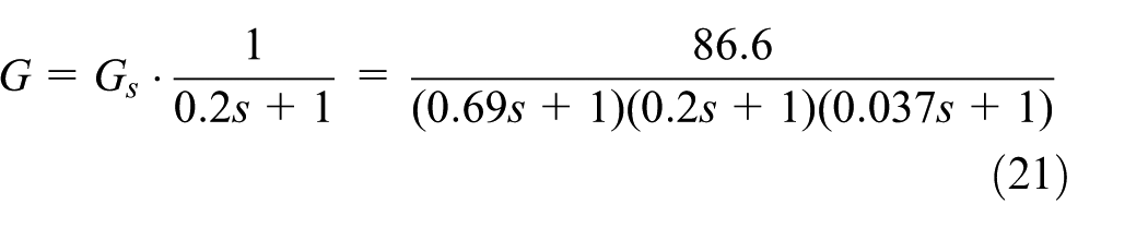
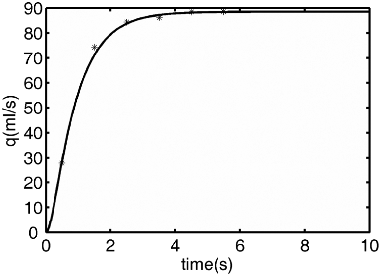
In order to verify the accuracy of the identification model, the experimental study is carried out. In theory, the least square method is a kind of systematic identification method without deviation, which can achieve very high accuracy. In practice, noise, sampling period, data length, and other factors will bring errors to the system identification. In this article, in order to ensure the precision, first, the sampling period (0.02 s) and data length that are suitable for the system are selected, and then the collected data are processed by filtering. The specific experimental process is that: first, sets the sampling period (0.02 s) and starts the fuel supply system through the fuel control cabinet, and a group of input and output data of the fuel supply system can be obtained by PLC, then the obtained input and output data are processed by filtering, and, finally, an identification model of the fuel supply system can be obtained using the method designed in this article. It can be written as

In order to compare the accuracy of the established model, the actual flow-rate step response data need to be obtained. Because there is a large shock of fuel flow rate when the electromagnetic valve is opened in the moment, a step response experiment of the fuel flow rate needs to be carried out in a stable operating point. In the experiment, first, the input voltage signal of VFD is set to 1 V, and then it is adjusted to 1.5 V after the fuel flow rate of the system is stable, so that the actual flow-rate step data are obtained. The step response curves of the experimental data without filter, the filtered experimental data, and the identification model are shown in Figure 10. From the figure it can be seen that there are noises in the actual fuel flow-rate response data, but the strength of the noise is small; the filtered experimental data are close to the response curve of the identification model, and the error of steady-state value is about 1%. Therefore, the gray-box model established in this article has high precision and can meet the requirements of the actual flow-rate control.

The comparison of the two models.
Conclusion
This article uses the method which combines the mechanism modeling method and system identification to establish the equivalence mathematical model of the fuel supply system. Through the theoretical analysis and experimental study in this article, the following conclusions can be drawn:
Because some parameters of the fuel supply system are changed as the time and work conditions changed, the accurate mathematical model of the system is obtained hardly using the mechanism modeling method.
The experimental result shows that the mathematical model of the fuel supply system established in this article has high precision and can be used as an actual model in the control of the fuel flow rate.
Because
Footnotes
Academic Editor: Hamid Reza Shaker
Declaration of conflicting interests
The author(s) declared no potential conflicts of interest with respect to the research, authorship, and/or publication of this article.
Funding
The author(s) disclosed receipt of the following financial support for the research, authorship, and/or publication of this article: This work was supported by Science and Technology Research Project of Hebei Province, China, under grant no. QN2015079.