
Abstract
In this article, hybrid factor is proposed for hybrid magnetic bearing. The hybrid factor is defined as the ratio of the force produced by the permanent magnet and the forces produced by the permanent magnet and current in hybrid magnetic bearing. It is deduced from a certain radial hybrid magnetic bearing using its important parameters such as the current stiffness and displacement stiffness at first and then the dynamic model of magnetically suspended rotor system is established. The relationship between structural parameters and control system parameters is analyzed based on the hybrid factor. Some influencing factors of hybrid factor in hybrid magnetic bearing, such as the size of the permanent magnet, length of air gap, and area of the stator poles, are analyzed in this article. It can be concluded that larger hybrid factor can be caused by the smaller power loss according to the definition of hybrid factor mentioned above. Meanwhile, the hybrid factor has a maximum value, which is related to control system parameters such as proportional factor expect for structural parameters. Finally, the design steps of parameters of hybrid magnetic bearing can be concluded.
Introduction
Nowadays, magnetic bearings have been widely used in actuators such as flywheels,1–3 control momentum gyro, 4 turbines, 5 and high-speed machines. 6 They can be divided into active magnetic bearing (AMB), passive magnetic bearing (PMB), and hybrid magnetic bearing (HMB). PMB has the characteristic of low power loss because of no current, 7 but it has lack of active control ability and low damping stiffness. On the contrary, AMB has good controllability and high stiffness, whereas it suffers from large power loss caused by the biased current. HMB is, therefore, getting more and more attention because it has advantages of PMB and AMB.8–11 The characteristic of HMB is that the main supporting force is produced by the permanent magnet. Consequently, the control current can be reduced compared with AMB, as well as the power loss.
As we all know, the power loss is small in HMB because the supporting force is produced by the permanent magnet.12–14 However, the negative displacement stiffness in HMB can cause the instability of the magnetically suspended rotor system. In Wu et al. 15 and Yang et al., 16 the relationship between stiffness of control system and structural parameters of AMB is presented. While it is aimed at proportional–derivative (PD) controller, and the relation is derived by simplified expression between proportion coefficient (kP) and differential coefficient (kD), which is not applied for HMB because the force produced by biased current and the force produced by control current are not considered. So, it is important for HMB to determine the relationship between parameters of HMB and control system.
In this article, hybrid factor is proposed using the displacement stiffness and current stiffness.17,18 Meanwhile, the mathematical expressions are given to describe hybrid factor and parameters of control system such as proportion coefficient (kP), differential coefficient (kD), and integral coefficient (kI) considering the stability of magnetically suspended rotor system. Some factors affecting hybrid factor are analyzed in this article and then the design principle of magnetic bearing is concluded based on hybrid factor.
Hybrid factor in HMB
An external rotor structure for a radial HMB is shown in Figure 1. 17 The structure consists of a permanent magnet and eight stator poles placed along the x and y directions. Two inner magnetic rings are placed on both sides of the permanent magnet along the z direction. Two groups of rotor core stacks are placed outside the stator poles, and the air gap is formed between the stator poles and the rotor core stacks. The rotor core stacks are connected by an outer magnetic ring.

Radial HMB: (a) sectional view and (b) end view.
The solid lines show the bias flux, and the dotted lines show the control flux paths in Figure 1. The bias flux path, which is produced by the permanent magnet, is across the outer magnetic ring, rotor core stacks, air gap, inner magnetic ring, and stator poles, as shown in Figure 1(a). The control flux path, which is produced by current, is across the stator poles, air gap, and rotor core stacks, as shown in Figure 1(b). Therefore, the equivalent magnetic circuits of the bias flux and the control flux can be drawn in Figures 2 and 3, respectively.

Bias flux equivalent magnetic circuit.

Control flux equivalent magnetic circuit.
Assuming that the reluctances of iron core stacks, inner magnetic ring, and outer magnetic ring are ignored, the force on the rotor in the x direction can be calculated by

When the rotor is at the equilibrium position,
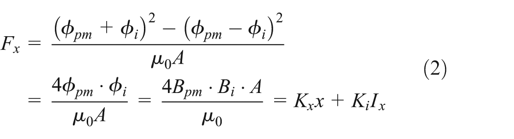
It can be seen that the force is related to the current of coil Ix and the displacement of the rotor. Then, the displacement stiffness (Kx) in the x direction can be derived according to equation (2) 18

Similarly, the current stiffness (Ki) can be calculated according to equation (2)

So, an important relationship between Kx and Ki can be obtained

At the same time, flux density in the air gap produced by the permanent magnet and current in coil can be derived according to equation (2)

The ratio between Bpm and Bi is given by
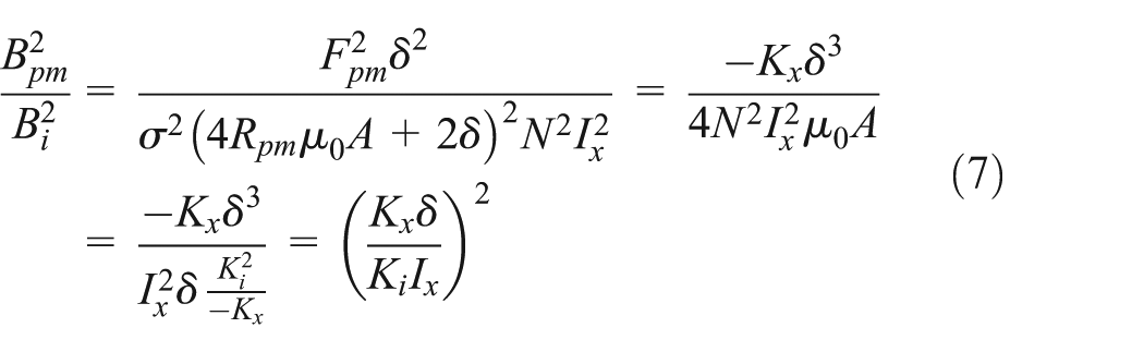
Therefore, the hybrid factor can be expressed as

It can be seen that the hybrid factor is determined by the ratio between the force produced by the permanent magnet and the force produced by current. From equation (2), Bpm is inversely proportional to Bi under the condition that the force Fx is constant. Consequently, when Kpmc is larger, and then Bpm is larger, Bi is smaller according to equation (8). In equation (7), we can see that larger Bpm leads to larger Kx, as well as Ki in equation (5), so the current Ix will be smaller according to equation (2) and then the power loss will be decreased in HMB. Hence, we can find that the larger hybrid factor will lead to the lower power loss.
When the gravity of rotor is known, equation (8) can be expressed in another form

In equation (9), the load capacity of magnetic bearing is set as half of the gravity force G/2 because the two radial magnetic bearings are usually adopted in magnetically suspended system.
The displacement stiffness and current stiffness can also be given by


It can be seen that the value range of Kpmc is 0–1 in equation (10). Meanwhile, larger Kpmc can lead to larger Kx accordingly. However, larger Kx can cause the instability of the magnetically suspended system. So, it is important to determine the maximum value of hybrid factor (Kpmcmax) considering control system parameters.
Relationship between control system parameters and structural parameters in HMB
The model of magnetically suspended rotor system is built as shown in Figure 4. In this figure, the magnetically suspended rotor system consists of displacement sensor, controller, power amplifier, magnetic bearing, and rotor. The magnetic poles of magnetic bearing are drawn in the x direction in this figure, and the definition of variables is seen in Appendix 1.

Model of magnetically suspended rotor system.
Dynamic model of magnetically suspended rotor system
According to Figure 4, the dynamic model of magnetically suspended rotor system is

It can be expressed in the matrix form

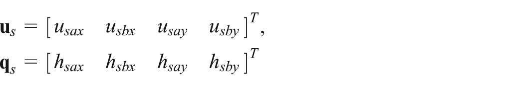
where

Model of force in HMB
The force and torque of magnetic bearings in the x and y directions are given by


It can be also expressed in the matrix form

where

According to Figure 4, displacement and angle can be obtained
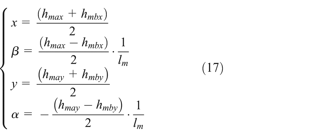
Suppose that

Then

The formulation is obtained by equations (17) and (14)


Model of control system in magnetically suspended rotor system
Input and output model of displacement sensor
Output voltage of displacement sensor model is expressed
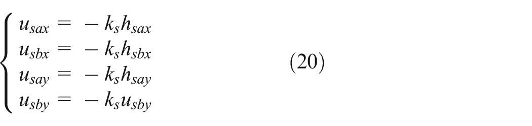
It can be shown in the matrix form

where
According to Figure 4, the length of air gap deviation in the x and y directions and the angles of rotation about x and y can also be indicated

Suppose that

Matrix form is given by

Input and output model of pulse-width modulation amplifier
Output voltage of pulse-width modulation (PWM) amplifier model is expressed

According to Figure 4, output current of PWM amplifier can be obtained
Suppose that

It can be shown in the matrix form

Suppose that the controller is decentralized controller, the input and output voltages can be given by

where gc is linear operator, then the matrix form is shown as follows


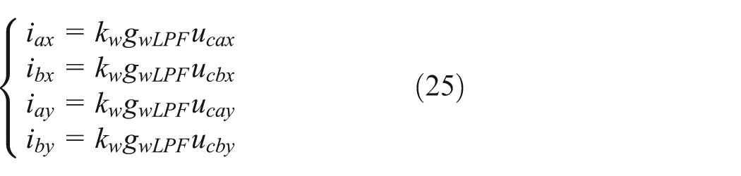
Consequently, the current is also expressed according to equations (23), (26), and (28)

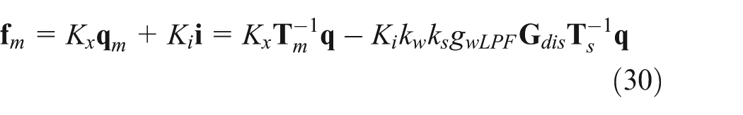
Substituting equations (18), (23), and (29) into equation (16), the forces can be obtained
Then, the dynamic model of magnetically suspended rotor system based on decentralized controller can be given as follows

The whole control system can be shown in Figure 5.

Diagram of magnetically suspended rotor control system.
Consequently, the dynamic model of magnetically suspended rotor system can also be expressed as

where
When proportional–integral–derivative (PID) control is used
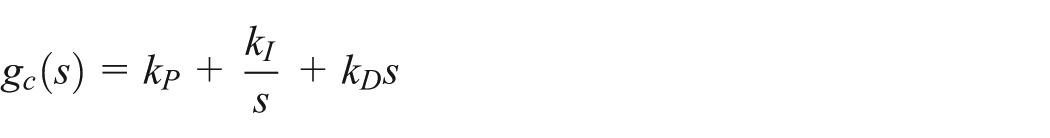
The formulation (32) can be changed as

According to Routh criterion, the stability condition of magnetically suspended rotor system is derived according to equation (33)

Considering structural parameters, equations (10) and (11), the stability condition can be expressed as

where
Relationship between hybrid factor and structure parameters in HMB
Based on the methods suggested above, the permanent magnet biased radial HMB is designed. The related parameters are shown in Table 1.
Main parameters of the radial HMB.

HMB: hybrid magnetic bearing.
Considering the structural parameters such as outer diameter of the permanent magnet Dpm1 (which affects the reluctance of permanent magnet Rpm), the length of air gap (δ) at the equilibrium position, the area of the stator poles (A), and the proportional coefficient kP can influence the hybrid factor according to equations (3), (9), and (35), analysis on hybrid factor will be introduced in detail.
To verify the correctness of the theoretical analysis, the three-dimensional (3D) finite element method (FEM) model is built, as shown in Figure 6.

3D FEM model of radial magnetic bearing.
Relationship between the hybrid factor and permanent magnet dimension
Dimension of the permanent magnet includes outer diameter, inner diameter, and its axial length. The following analysis takes the outer diameter change as an example, assuming that other parameters are unchanged.
Curve between hybrid factor Kpmc and the permanent magnet outer diameter Dpm1 is shown in Figure 7.

Variation of hybrid factor Kpmc with the permanent magnet outer diameter Dpm1.
In this figure, it can be seen that when the permanent magnet outer diameter Dpm1 is increased, the permanent magnet reluctance Rpm is decreased because of the equation
Relationship between the hybrid factor and the length of air gap
Curve between hybrid factor Kpmc and the air gap length δ at the equilibrium position is shown in Figure 8. As the air gap length δ at the equilibrium position is increased, the displacement stiffness Kx will be decreased according to equation (3). Accordingly, the hybrid factor Kpmc will be decreased according to equation (9).

Variation of hybrid factor Kpmc with the length of air gap δ.
Relationship between the hybrid factor and the area of the stator poles
Curve between hybrid factor Kpmc and the area of the stator poles A is shown in Figure 9. As the area of the stator poles A is increased, the displacement stiffness Kx is decreased according to equation (3). So, the hybrid factor Kpmc is decreased according to equation (9).

Variation of hybrid factor Kpmc with the area of the stator poles A.
From these simulation results above, it can be seen that the difference between MATLAB and 3D FEM analysis is mainly the different leakage flux and iron saturation caused by different permanent magnet dimensions, air gap length, the stator poles area, and so on.
Considering the system stability, the proportional coefficient kP is the most important parameter in PID parameters. The change of kP has influence on the hybrid factor. According to equations (34) and (35), the simulation parameters are as follows: KI = 0.428, KD = 0.0136, Kw = 0.0893, KS = 17,500, and m = 7.35. Figure 10 shows the curves of hybrid factor and its maximum with different diameters of permanent magnet Dpm1 with different proportional coefficients kP = 1.93 and kP = 3.03. In this figure, the solid line denotes the relationship between outer diameter of the permanent magnet and hybrid factor which is the same as Figure 7 without considering control system parameters, and the dotted line denotes the relationship between outer diameter of the permanent magnet Dpm1 and maximum hybrid factor Kpmcmax which is obtained according to equation (35).

Variation of hybrid factor Kpmc with its maximum with different diameters of the permanent magnet Kpmcmax: (a)
From this figure, it can be seen clearly that the hybrid factor cannot be increased infinitely in view of control system parameters. As the proportional coefficient kP is increased, the maximum hybrid factor is increased accordingly. Considering external disturbance and system noise, the proportional coefficient kP cannot be increased infinitely, so the hybrid factor need to be less than certain values when the proportional parameter can be set as a constant value.
Conclusion
In this article, hybrid factor about HMB has been put forward. It refers to the ratio of the force produced by the permanent magnet and the forces produced by the permanent magnet and current in HMB. Considering a radial HMB as an example, the relationship between hybrid factor and structure parameters has been analyzed, such as permanent magnet outer diameter, air gap length, and the area of the stator poles. Analysis results show that the larger hybrid factor will lead to lower power loss. Meanwhile, the hybrid factor has a maximum value, which is related to control system parameters of PID especially proportional factor kP. Therefore, the design steps of parameters in magnetic bearing can be concluded, and the hybrid factor Kpmc is determined first according to equation (35) under the condition that the PID parameters are known and then the displacement stiffness Kx and current stiffness Ki are determined according to equations (10) and (11), in which the length of air gap is set. Finally, the other parameters of magnetic bearings are determined according to the displacement stiffness Kx and current stiffness Ki.
Footnotes
Appendix 1
Academic Editor: Fakher Chaari
Declaration of conflicting interests
The author(s) declared no potential conflicts of interest with respect to the research, authorship, and/or publication of this article.
Funding
The author(s) disclosed receipt of the following financial support for the research, authorship, and/or publication of this article: This work was supported by the National Natural Science Foundation of China (grant no. 51575025), Preliminary Exploration of Project (grant no. 7131474), and Foundation for the Author of National Excellent Doctoral Dissertations of China (grant no. 201330).