
Abstract
Vehicles driven by in-wheel motors have received more and more attention. However, due to the introduction of in-wheel motors, the ratio between unsprung and sprung mass is increased. In this article, to study the influence of this change on ride comfort of vehicles driven by in-wheel motors, an 11 degrees of freedom of vehicle ride comfort model will be presented and studied with MATLAB/Simulink. Then, road tests will be conducted to corroborate the simulation results. It can be obtained that the vehicle ride comfort becomes poor with the increasing unsprung mass. Finally, semi-active air-suspension proportional–integral–derivative control system will be proposed to improve the vehicle ride comfort. Through the simulation results, one can come to a conclusion that the proportional–integral–derivative control system for air suspension is feasible and effective to improve the ride comfort of the vehicles driven by in-wheel motors.
Introduction
Scarcity of fuel has brought great concerns to us today. Gasoline, which has been the major power source of classical vehicles for decades, got its price soaring up year by year, which results in an unstoppable trend of conventional cars being replaced by vehicles powered not by gasoline but other new energy, such as electric vehicles (EV). However, the cost of devices of EV is always considerable. In-wheel motor EV presents us a practical way of designing an EV with its cost reduced and at the same time performance improved compared to traditional vehicles, also this structure is likely to be the ultimate form of EV design. 1 Vehicles manufactured in this way need not to be armed with complex gearbox, heavy transmission shaft, and so on, and the drive torque can be controlled directly by the motor. The performance of in-wheel motor EV is likely to perform better compared with that of classical vehicles once a good control system is invented.2,3 The advantages of EV driven by in-wheel motors does not stop there. Motor could recover energy from kinetic of EV during braking, which is remarkably valuable for future use. 4 Motor can unleash torque very quickly and accurately. The value of torque with this feature is demonstrated by some researchers. 5 Motorized electric vehicles (MEV) can assist steering by differentiating torque to the left and right wheel motors, 6 which in turn lower the hand toque burden. The driver motion signal, which is generated by the driver, is converted to the reasonable torque of the in-wheel motors that is attached to each wheel by the motor controller through the electronic control unit (ECU). It is, however, unsprung mass of this kind of structure is added because of the motor attached to the wheels. From a test of in-wheel motor that is used in Bora (a car from Volkswagen), a result can be obtained that the mass of this motor is almost the same as the wheel.
In recent years, a great number of studies have been engaged in the research about the ride comfort of EVs. DJ Van Schalkwyk and Kamper 7 studied the effect of hub motor mass on stability and comfort of EVs. J Zhang studied the drivability of hybrid EV and presented some methods to improve the drivability based on experiment results. And results showed that optimization of clutch control and cooperation of the engine and the motor on speed and torque are effective in reducing the jerk of vehicle. 8 To study the ride property of vehicles driven by in-wheel motors, in this article, 11 degrees of freedom (DOF) of vehicle ride comfort model is built. Different with traditional vehicle ride comfort models that has been established before, 9 the introduction of in-wheel motors is considered in this article. Then, road tests will be conducted to corroborate the simulation results. Finally, semi-active air-suspension proportional–integral–derivative (PID) control system will be proposed to improve the ride comfort. Previously, some researchers have studied EV active suspension. J-T Cao et al. 10 proposed an improved half-vehicle model for EV active suspension control systems and implemented three control strategies into the proposed model. There are several control algorithms in modern control theory applied to vehicle suspension. The real-time and robustness of control system can be efficiently improved because of the simple configuration of PID control algorithm and the parameter easy tuning. Therefore, PID control algorithm will be adopted to adjust the air pressure of the bumper of air spring. Compared to conventional passive suspension system, the proposed semi-active air suspension PID control system is feasible and effective to improve the ride comfort of the vehicles driven by in-wheel motors.
Vehicle ride comfort model
Ride comfort of mechanical model
Automobile is a complex system. According to the research direction and the main research issues, the automobile system is simplified. In theory, the more the freedom to choose, the more close to the actual situation. However, more parameters are required and instead the error is greater. Therefore, the DOF should be selected properly according to the characteristic of the research content. 11 DOF of vehicle model is selected in this article as shown in Figure 1, including the body’s vertical vibration, roll, pitch, and the vertical vibration of four wheels and four seats.

The 11 DOF of vehicle ride comfort model.
Mathematical model of ride comfort
According to the established mechanical ride model above, the corresponding mathematical model is established. According to the geometric relations, the mathematical model is established using Newton’s method.
Assuming the vertical displacement of the suspension and the body connection point is

And the motion equations of the four seats also can be written as
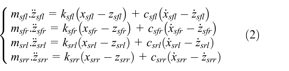
And the body’s vertical, pitch, and roll motion equations can be given as


According to the above equations, the displacement, velocity, and acceleration of four wheels, body, and four seats and the body’s pitch and roll angle can be derived. The mass distribution of vehicle is different under the manned and unmanned condition. And the mass distribution will affect the acceleration of seat and vehicle body. The mass distribution of each seat and different position of passenger comfort are taken into account in the model established in this article, and this makes it closer to the actual situation. Besides, it is reasonable and necessary.
In modeling, the main vehicle parameters required in the model are obtained through the data given by the factory, the actual measurement, and the reasonable estimate. In this topic, the EV which is refitted by some A-class automobile is selected as a simulation object. The parameters are shown in Table 1.
Vehicle basic parameters.

Simulation of the vehicle ride comfort
Establishment of random road
Road roughness means that road surface relative to the datum plane height q changes with the length of road pavement. Road roughness could be measured by leveling instrument and pavement gauge. When using computer simulation, road roughness data are usually processed into pavement power spectral density (PSD) to describe. In the time domain simulation environment, the road vibration characteristics can be characterized as a stationary Gaussian random process. Road roughness can be described as a time-varying function. The stochastic excitation time domain road model is established in this article based on the filtered white noise method. The mathematical description can be written as 11

where
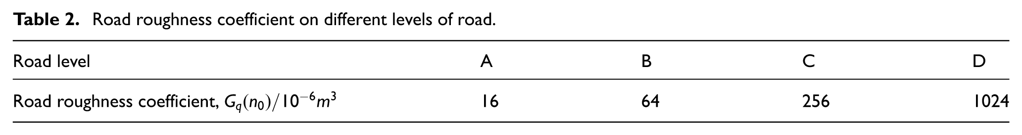
Road roughness coefficient on different levels of road.
The mathematical description of PSD of road excitation in terms of temporal frequency can be written as

where
Taking B-class pavement, speed u = 50 km/h, for example, the road excitation on B-class road for front wheel is shown in Figure 2, and the PSD of road excitation in terms of temporal frequency is shown in Figure 3.

Front wheel road excitation on B-class road.

PSD of road excitation in terms of temporal frequency.
Analysis of simulation results
According to the established comfort model above, take B-class pavement as road excitation input and perform the ride comfort simulation under random vibration input. On the B-class road, the vehicle travels at a constant speed of 50 km/h. Start simulation with the original data
The vertical load of each wheel changes when the vehicle moves on different road. According to the mechanics principle, take the front left wheel as example, and the dynamic tire load calculation formula can be written as 12

The relative dynamic tire load is equal to the dynamic load divided by the static tire load.
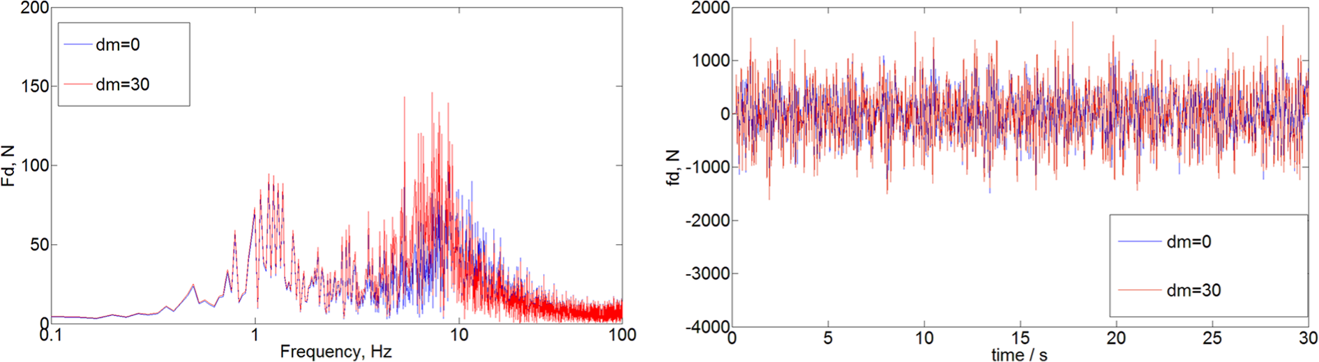
The contrast of the rear left wheel-relative dynamic load when the increment in unsprung mass is initial value and 30 kg.
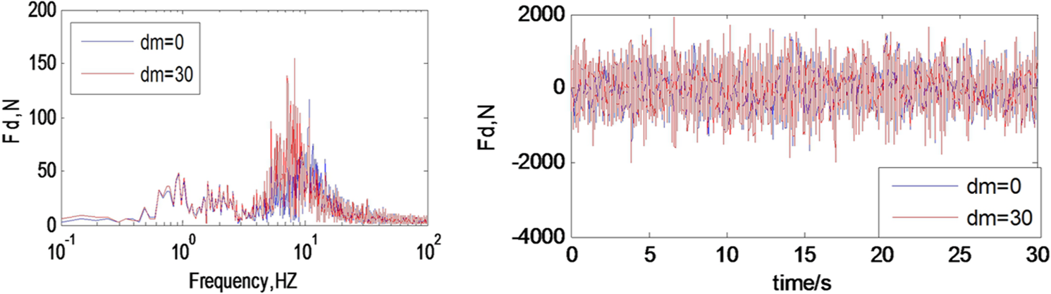
The contrast of the front left wheel-relative dynamic load when the increment in unsprung mass is initial value and 30 kg.
From the body equilibrium position on, suspension allows the maximum compression stroke which is the limit travel
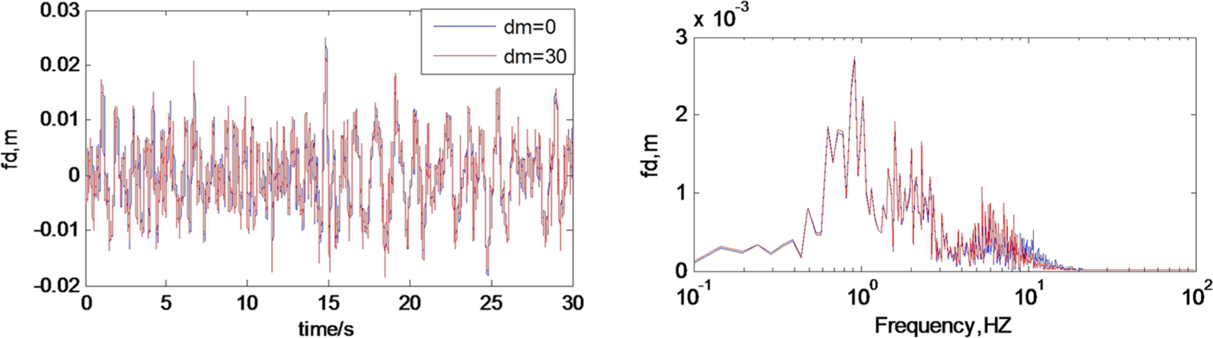
The contrast of front left suspension dynamic deflection when the increment in unsprung mass is initial value and 30 kg.
It can be seen from the simulation curve that the dynamic tire load significantly becomes lager, and suspension dynamic deflection increases slightly when unsprung mass increases 30 kg compared with the initial value. Changing the tire mass has a great influence on automobile ride comfort. So, the study on the change of ride comfort evaluation index caused by change of unsprung mass is necessary.
Road test results and analysis
Through the simulation analysis above, it can be proved that the increase in unsprung mass has a great influence on the EV ride comfort. In order to corroborate the simulation results, road test will be carried out in this section.
Road test scheme
According to the provisions of the file GB/T 4970-2009 “Method of running test—automotive ride comfort,” 13 considering the cost and making the test easier, the EV which has been modified well is not used to do road test, instead the Yaris car is used. Research is carried out through installing unsprung mass disks on its wheels. Test vehicle and installation of unsprung mass are shown in Figures 7 and 8, respectively.
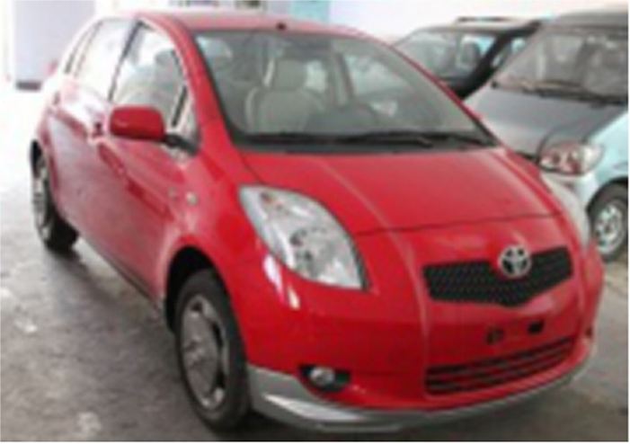
The Yaris car.

Installation of unsprung mass.
The increment in unsprung mass is processed, respectively, to the mass disk of 5, 10, 15, and 20 kg which are used in this experiment. And they are installed on four wheels in the way of increasing in turn. The vehicle body acceleration sensor is installed in the driver’s seat on the left side of the front row. Use data acquisition to collect experimental data and process the experimental data by computer, come to conclusion, and then compare with the results of the simulation analysis.
Road test
Road test when unsprung mass is initial value
According to the provisions of GB/T 4970-2009 “Method of running test—automotive ride comfort,” after equipment is installed, the vehicle road test is carried out under the full-load condition when unsprung mass is initial value.
Figure 9(a) is the body vertical vibration acceleration curve when the car drives from start to 40 km/h speed. Where 0–100 s is the time when the car speeds up to 20 km/h, 100–250 s is the time when vehicle moves at a constant speed of 20 km/h, 300–400 s is the vehicle running at 30 km/h, and 450–550 s is the vehicle moving at a constant speed of 40 km/h. It can be seen from the diagram that the change of the body vertical vibration acceleration curve is not obvious when the speed is at 20 and 30 km/h, which shows that the speed has a low effect on vehicle ride comfort at low-speed stage. While when the car moves at a constant speed of 40 km/h, body vertical vibration acceleration vibration amplitude increases obviously. It is shown that the speed still has an influence on vehicle ride comfort with speeding up.
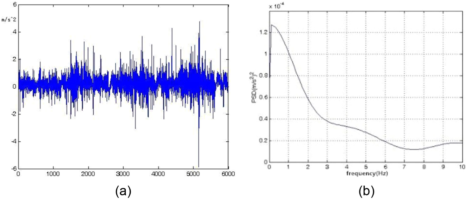
(a) The body vertical vibration acceleration and (b) PSD curve when unsprung mass is initial value.
In order to make it easy to compare with the vertical vibration acceleration curve of the body that added unsprung mass, use MATLAB to process and obtain the PSD curve as shown in Figure 9(b). It can be seen from the figure that the maximum peak of the body vertical vibration acceleration curve is 1.25 × 10⁻⁴ (m/s2)2 in the low-frequency phase, while in the high-frequency phase, the body vertical vibration acceleration do not change basically.
Road test when the increment of unsprung mass is 20 kg
According to the test requirements, 20 kg disks are added on the four wheels coaxial of the test vehicle. And experiments are carried out under the same pavement condition and the same speed.
From the curve shown in Figure 10, the maximum vibration amplitude of the body vertical vibration acceleration PSD curve is 5.9 × 10⁻⁴ (m/s2)2 in the low-frequency phase. Compared with the maximum vibration amplitude when unsprung mass is initial value, it can be discovered easily that the vehicle ride comfort becomes very poor when unsprung mass increases 20 kg.

(a) The body vertical vibration acceleration and (b) PSD curve when unsprung mass increases 20 kg.
Simulation of PID control system for air suspension
From the results obtained above, a PID control system is designed to improve the vehicle ride comfort. When the PID control strategy is applied, its three parameters (Kp, Ki, Kd ) play a decisive role in the control effect. Using the empirical formula of the MATLAB software makes qualitative reference. And according to the performance requirements of air suspension and some experience of parameter tuning, satisfactory parameters can be ascertained finally by selecting different parameters to simulate. This is not only direct, convenient, and less calculation but also easy to adjust and improve. The steps of parameter tuning are that first proportional, then integral, and at last for the differential with try-and-error method. The three parameters of PID control are determined: Kp = 0.5, Ki = 0.1, and Kd = 0. The input variables are synthetical values of sprung mass acceleration, suspension dynamic deflection, and dynamic tire load, and output variables are stiffness of air spring. The structure of PID control system is shown in Figure 11.

Structure of PID control system.
Electronically controlled air-suspension system is simulated using MATLAB/Simulink software for performance. To further observe controller performance, a large road bump is used as disturbance. In this article, stone block pavement is chosen. The road surface is E level, road roughness is

Suspension dynamic deflection of (a) time domain and (b) frequency domain.

Vertical vibration acceleration of sprung mass of (a) time domain and (b) frequency domain.

Dynamic tire load of (a) time domain and (b) frequency domain.
It can be seen from the figures that in comparison with passive suspension, PID control air suspension can effectively reduce the vertical vibration acceleration of sprung mass, suspension dynamic deflection, and dynamic tire load. The performance of the PID control air suspension is better than passive suspension. With stone block road condition, forward speed 50 km/h, and sprung mass to unsprung mass ratio 4.576, it has 22.1% drops on suspension dynamic deflection, 9.3% drops on vertical vibration acceleration of sprung mass, and 8.5% drops on dynamic tire load. So, it can be drawn that the PID controller proposed in this article could improve the ride comfort of vehicles driven by in-wheel motors.
Conclusion
In this article, 11 DOF vibration model of the EV driven by in-wheel motors and white noise pavement incentive model are established in the software MATLAB/Simulink. Through the simulation, the theoretical results can be obtained that on B-class road, when the speed is constant, the vertical weighted acceleration root-mean-square (RMS) values are almost the same with increasing unsprung mass. Besides, the dynamic deflection of suspension increases slightly. However, the dynamic tire load increases significantly.
Then, road tests are carried out to verify the computer simulation. Through the simulation and experimental results, the conclusion can be drawn that the increase in unsprung mass do have an influence on the ride comfort of the vehicles driven by in-wheel motors. To solve the problem, a semi-active air suspension PID control model is built. And from the simulation results, it is found that the PID control strategy is effective to improve the ride comfort of the vehicles driven by in-wheel motors.
Footnotes
Academic Editor: Hamid Taghavifar
Declaration of conflicting interests
The author(s) declared no potential conflicts of interest with respect to the research, authorship, and/or publication of this article.
Funding
The author(s) disclosed receipt of the following financial support for the research, authorship, and/or publication of this article: This work was supported by the National Science Foundation of China (E50907030) and China Postdoctoral Science Foundation (2013M540248).