
Abstract
In this study, an electric-vehicle-based thermal management system was designed for dual energy sources. An experimental platform developed in a previous study was modified. Regarding the mechanical components, a heat exchanger with a radiator, proportional valve, coolant pipes, and coolant pump was appropriately integrated. Regarding the electric components, two heaters emulating waste heat were controlled using two programmable power supply machines. A rapid-prototyping controller with two temperature inputs and three outputs was designed. Rule-based control strategies were coded to maintain optimal temperatures for the emulated proton exchange membrane fuel cells and lithium batteries. To evaluate the heat power of dual energy sources, driving cycles, energy management control, and efficiency maps of energy sources were considered for deriving time-variant values. The main results are as follows: (a) an advanced mechatronics platform was constructed; (b) a driving cycle simulation was successfully conducted; and (c) coolant temperatures reached their optimal operating ranges when the proportional valve, radiator, and coolant pump were sequentially controlled. The benefits of this novel electric-vehicle-based thermal management system are (a) high-efficiency operation of energy sources, (b) low occupied volume integrated with energy sources, and (c) higher electric vehicle traveling mileage. This system will be integrated with real energy sources and a real electric vehicle in the future.
Introduction
Motivation
To increase the overall efficiency of dual-energy-source electric vehicles (EVs), maintaining the optimal operating temperatures of the dual energy sources is crucial. Therefore, in this study, a mechatronics design of a novel electric-vehicle-based thermal management system (EVTMS) was developed; this design was modified from that presented in a previous study. 1 The innovative concept is to utilize only one set of cooling systems with a proportional valve to manage two heat sources. Through this design, the EVTMS can attain high-efficiency operation of energy sources, low occupied volume of the thermal management system (TMS), and higher traveling mileage of EVs. The EVTMS concept can be extended to dual power sources (motor and engine) in hybrid electric vehicles (HEVs).
Literature survey
The concept of hybridization of dual energy or power sources has been commonly used in advanced vehicles for maximizing the output performance of such vehicles and simultaneously compensating for individual drawbacks.2,3 For hybrid vehicles, engines, motors, and generators are the three main power sources that have individual optimal operating temperatures. For EVs, green energy sources, such as batteries, supercapacitors, and proton exchange membrane fuel cells (PEMFCs), have optimal operating temperatures.
Temperature influences the operating efficiency, life cycles, and output performance of batteries. Therefore, many studies have focused on the thermal management and system analysis of battery modules. In Xiongwen, 4 the thermal analysis of a battery was conducted, and this study reported that the effective heat dissipation increases the output efficiency of the battery. The thermal dynamics of a battery as well as cooling systems for EVs and HEVs were modeled in Pesaran and Keyser. 5 Various types of TMSs were examined to control overheated conditions inherent at high power outputs. Ye et al. 6 proposed that thermal management effectively enhances the battery discharge efficiency and extends the battery life cycle. In Rao et al., 7 to reduce the EV cost and extend the battery life cycle, battery thermal management was enhancing the EV traveling mileage. Experiments conducted in previous studies8,9 have confirmed that the battery temperature considerably affects the output performance of EVs and HEVs. Three types of TMS have been analyzed.
For analyzing the temperature effects and thermal management of PEMFCs, a thermal PEMFC model was developed in Shan and Choe; 10 four factors, namely, temperature gradient, proton concentration, water concentration, and reactant concentration, were considered. The parameter/system can be optimized using the model. Moreover, in Zhang et al., 11 a PEMFC thermal model was constructed, and a lumped thermal mass model was used. The simulation and experimental results were compared, revealing that the model can be used for analyzing the temperature of components. A study 12 reported the challenges of thermal management, and it showed that current technical limitations can be overcome through various novel methodologies that include increasing the efficiency of components, reducing component size and mass, and conducting detailed modeling. In Lee et al., 13 the TMS was reported to influence the output power of PEMFCs. In addition, the effects of waste heat and heat transfer to the output power were investigated. Nguyen and White 14 created a model for analyzing the performance of PEMFCs, and they reported that effective water and heat management are essential for obtaining high-power-density performance and high energy efficiency for such fuel cells.
This study modified an experimental platform implemented in a previous study 1 and further simulated the transient heat generated by an EV in driving cycles. The major differences between these platforms are as follows: (a) a rapid-prototyping controller was used with online calculation, which delivers the required waste power to dual energy sources; (b) programmable power supplies, which represent the dual energy sources (one for the battery and the other for the fuel cells), were integrated for real-time simulation; and (c) the mechatronics design of this EVTMS was reconstructed with new components and parts. These differences render this novel TMS more accessible for real EVs compared with the system designed in Hung et al. 1
Mechatronics and controller
Platform establishment
Figure 1 illustrates the concept of the EV-based hybrid TMS. Two heat sources in the middle represent the waste heat generated by the green energy sources of EVs, which is controlled by two programmable power supply machines. The time-variant heating commands are sent through LabVIEW on a PC. A proportional valve governs the coolant flow from the two paths to the two heat sources. The total flow rate was determined using an electric coolant pump, whereas the heat was removed from a heat exchanger. For the control segment, two temperature signals are fed back to a rapid-prototyping controller, which controls three commanded voltages of the three actuators, namely, the valve, pump, and radiator, on the heat exchanger.

Concept of the electric-vehicle-based hybrid thermal management system (TMS).
On the basis of the concept illustrated in Figure 1, a measurement part was also designed (Figure 2). 15 Six temperature sensors placed at the entrances and exits of the two heat sources and heat exchanger separately evaluate the heat generation or heat dissipation capacity (each heat source or heat exchanger is equipped with two sensors). Two flow meters, placed after the proportional valve, detect the two flow rates. A data logger records the variation in key parameters, whereas the LabVIEW software package calculates the heat generation command of the two power supply machines. The power supply machines and proportional valve are provided with AC electricity (110 V).

System configuration of the TMS.
Figure 3 demonstrates the components selected for the experimental platform, which are as follows: (a) PC with LabVIEW; (b) self-made stainless tanks; (c) heaters (TU 3/8 STX240; Chin-Ta Heating, Taiwan); (d) temperature transducers (TRH-300; TECPEL, Taiwan); (e) rapid-prototyping controller (Microbox; Terasoft, Taiwan); (f) proportional valve (AN-01-AMD-360; ANCO Engineers, USA); (g) heat exchanger (Radiator 240; Xigmatek, Taiwan); (h) coolant pump (U85B1; Little Giant Pump, USA); (i) coolant reservoir; (j) AC inverter; (k) flow meter; and (l) data logger. The platform can be constructed by connecting and assembling these elements.

Experimental platform of the EVTMS.
Heat generation
To emulate the waste heat generation of dual energy sources for a light-duty vehicle, related equations must be presented. First, the road load power of a fuel cell/battery EV can be expressed as

where P, F, V, m,


According to equation (3), the waste heat could be derived as the total theoretical power of the dual heat sources (i.e.

Online heat generation (software and hardware).
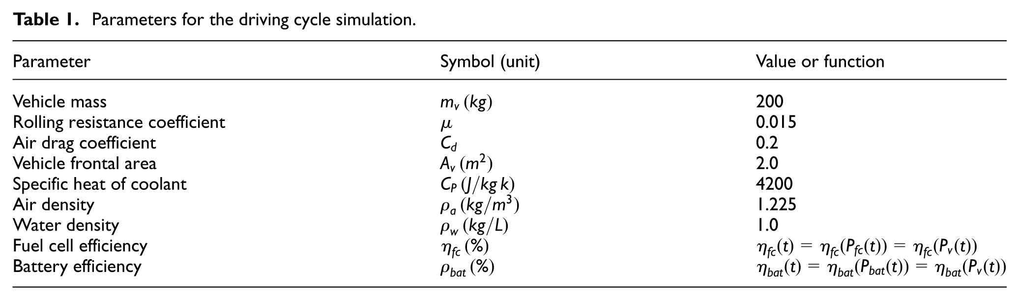
Parameters for the driving cycle simulation.
Control strategies and rapid-prototyping controller design
To appropriately maintain the optimal operating temperatures of simulated fuel cells and batteries, an if-else rule-based control was coded on the Stateflow platform. Similar rules are available in Hung et al. 1 The control laws determine the control voltage of the proportional valve, coolant pump, and radiator. The rules were written for three actuators as follows:
(a) Proportional valve If Elseif
Elseif
Elseif End
(b) Electric-controlled radiator If Elseif
End
(c) Coolant pump If Elseif
End
where T, K, Δt, and V represent the temperature, incremental gain, sampling time, and voltage, respectively, whereas the subscripts a, g, pv, fan, and pump represent the actual, optimal goal, proportional valve, fan (radiator), and coolant pump, respectively. The actuators are operated in the following order: the proportional valve, radiator, and finally, the coolant pump. (a) For the proportional valve, because the actual temperatures of the dual sources are both lower than the target values, the valve is at the middle position (Vpv
= 0.6), where the flow rates for the two coolant pipes are almost equal. When one of the coolant temperatures exceeds the target value, the voltage changes so that the two flow rates are different, thus inducing different waste heat. For example, if

Rule-based control and controller for three actuators.
Results and discussion
Performance tests of components
An experiment was conducted to verify the operation and relationships among three actuators in advance. First, 3000 cm3 coolant water was filled in the whole TMS without any air inside the pipes. The first test was for the coolant flow rates at two paths versus the commanded voltages of the proportional valve at fixed coolant flow rates. Two flow rate meters were placed at the entrances of the stainless tanks of emulated energy sources. For higher proportional valve voltages, the coolant flow rates to the emulated PEMFCs increased. By contrast, the coolant flow rates to the emulated battery increased as the voltages decreased. The simulated coolant flow rates of the dual paths equals the total flow rate of the coolant pump (Figure 6).

Coolant flow rates versus commanded voltages of the proportional valve.
Figure 7 illustrates the heat dissipation experiments involving three radiator voltages (4, 9, and 15 V) at various coolant flow rates (1, 2, and 3 L/min) and two fixed inlet temperatures (30°C and 35°C; the environmental temperature was 26°C). The heat dissipation capacity of the heat exchanger can be obtained from the basic heat flow rate formula

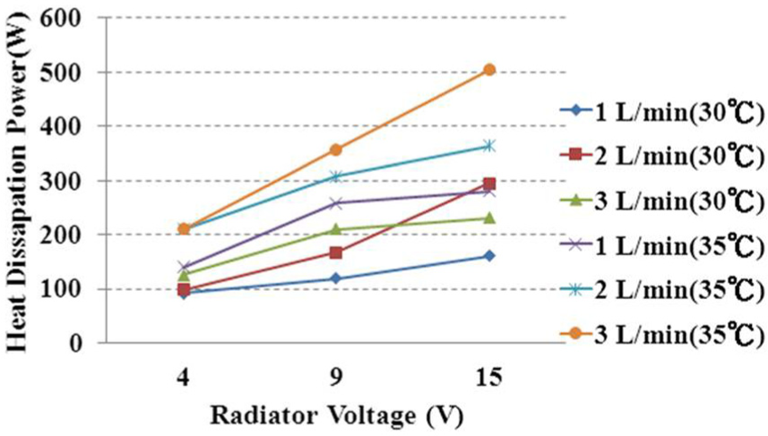
Relationships among fan voltages, coolant flow rates (1, 2, and 3 L/min), and constant inlet coolant temperatures (30°C and 35°C).
where
Driving cycle test for time-variant heat generation
In this experiment, the heating power was determined to simulate the real operation of an EV in a driving cycle. A standard driving cycle, ECE 40, was used as the test scenario. The 195-s cycle was repeated to investigate the temperature variation. According to equations (1)–(4), the total waste heat of the emulated batteries and fuel cells was evaluated through the parameters presented in Table 1.
As shown in Figure 8, with a comparatively higher efficiency, the battery produced less heat (max. 230 W), whereas the PEMFCs generated a maximum waste heat power of 700 W during the third acceleration period of the driving cycle. Sending the heating command from LabVIEW to the two power supply machines and the heating power to the two heaters in the two stainless tanks (Figure 4) caused the temperatures of the emulated energy sources to start increasing.

Illustration of the heating power of (a) emulated lithium batteries and (b) PEMFCs.
As illustrated in Figure 9, the emulated energy sources ultimately reached their optimal operating temperatures. For the emulated batteries, the temperature increased from the atmospheric temperature (26°C) to the target value (40°C) at nearly the 1000th second, whereas the emulated fuel cell coolant temperature reached the target value at nearly the 400th second (55°C). However, the temperature then dropped to 42°C and gradually increased to the target value again and stabilized. Figure 9 shows the temperature profiles, and section “Control strategies and rapid-prototyping controller design” describes the control laws.

Temperature variation of (a) emulated lithium batteries and (b) PEMFCs.
Figure 10 presents the command voltages for three key components based on the control laws in section “Control strategies and rapid-prototyping controller design.” For the proportional valve, because the emulated fuel cell and battery temperatures were lower than the target values in the beginning, the valve voltage was set to the initial value of 0.6 V (labeled 1). As the emulated fuel cell temperature exceeded 55°C at the 400th second, according to the control laws of (a) the proportional valve, the valve voltage was gradually increased at each time step (labeled 2) to the maximal value of 1.0 V to increase the coolant flow rate of the emulated fuel cell. Therefore, the temperature dropped to 45°C. Moreover, because the temperatures of these two sources were lower than the target values,

Command voltages for three key components: (a) proportional valve, (b) radiator, and (c) coolant pump.
Conclusion
This study established a novel EVTMS. The conclusions and contributions are summarized as follows:
Calculation of time-variant waste heat: on the basis of the vehicle dynamics and fuel cell/battery efficiency levels, time-variant waste heat was derived for the given driving cycle.
Rapid-prototyping controller: a two-input (temperatures of dual energy sources) and three-output (proportional valve, coolant pump, and radiator) rapid-prototyping controller was used to control the temperatures. The rule-based control strategy was designed on the MATLAB/Simulink/Stateflow platform and was downloaded to the controller for real-time control.
EVTMS establishment: the system comprises two programmable power supply machines controlled using LabVIEW, three actuators, and various types of sensors. The experimental results proved that the temperatures can reach the optimal ranges in the transient heating simulations.
Contribution and future developments: the advantages of the EVTMS are high-efficiency operation of energy sources, low occupied volume of the TMS in the limited EV space, and higher EV traveling mileage (because of higher energy efficiency). The concept of EVTMS can be extended to dual power sources (motor and engine) in HEVs. The EVTMS system as well as the rapid-prototyping controller will be implemented in a real EV or HEV in the future. Moreover, a theoretical analysis for optimal system design or flow distribution will be conducted.
Footnotes
Acknowledgements
The authors thank associate professor Yeou-Feng Lue from the Department of Industrial Education, National Taiwan Normal University, for his comments and suggestions on this study.
Academic Editor: Stephen D Prior
Declaration of conflicting interests
The author(s) declared no potential conflicts of interest with respect to the research, authorship, and/or publication of this article.
Funding
The author(s) disclosed receipt of the following financial support for the research, authorship, and/or publication of this article: The authors thank the Ministry of Science and Technology, the Republic of China, Taiwan, for the financial support provided for this research under contract no. 104-2221-E-003-025.