
Abstract
A new kind of measuring principle of reading data across the diameter of a target image is proposed for high-accuracy measurements of artillery-chamber parameters. A new kind of ruler target mechanism is designed to read the cross-diameter data. The ruler target mechanism is pushed into the chamber by a driver mechanism. It moves along the axis of the chamber, and the sequence images are collected. The radial displacement of the cross-measurement claw can be obtained by processing the change of inscribed lines on the ruler target, and the current diameter, volume and conical degree of the chamber can all be acquired by referring to the demarcating annulus size. Measurement precision is analysed based on error propagation theory, with the diameter and volume parameters as examples. According to this principle, the measurement prototype is designed, and experiments are conducted on it. We show that the measurement error of the diameter is no more than 10 µm, and the volume error of the artillery chamber is less than 2‰, which satisfies the practical engineering requirement.
Introduction
An artillery chamber is a space that accommodates the gunpowder case, obturator and propellant powder and ensures that the powder burns. The chamber volume is a static parameter for artillery, which affects loading density, breech pressure and the value of the initial velocity of the artillery projectile and also affects the range of artillery, the trail of trajectory, the accuracy of the ammunition’s fire point and the safety of the artillery’s launch.1–3 With an increase in the size of the projectile, the diameter and length of the chamber will increase with the repeated rapid expansion pressure of gunpowder burning gases, and the volume of the chamber will also increase. Therefore, the parameters of the chamber must be measured directly. At present, the methods of chamber parameter measurement include saline injection, sonic testing4–6 and laser light projection,7–10 inter alia. However, these methods have the disadvantages of complex operation, low efficiency, low accuracy or one single parameter of measurement, so they cannot meet the requirement of artillery firing range for high-performance measurement.
Structural features of the chamber and measurement system
Structural features of the chamber
As shown in Figure 1, the structure of chamber is a multistage vertebral body that includes several cones and one transition cone. With bullet launch, the transition cone will extend in the barrel direction, which makes the chamber volume increase. Due to its irregular shape, the diameter, length and volume are all static parameters that should be measured.

Schematic diagram of chamber section.
Measurement system
As can be seen from Figure 2, the system mainly constitutes a host computer, an axial displacement precision driving and controller device, a measuring section (that includes a charge-coupled device (CCD) camera, a three-jaw centring mechanism, a ruler target for image and a scene illumination system) and an auxiliary device of the barrel-rear. The measurement section is pushed by an axial displacement precision driving mechanism and is moved forward along the chamber axis in certain steps, according to the order of host computer, and collects intermittently field optical image information. The host computer processes the acquired optical image information and then obtains the diameter value of the corresponding location and displays the result for user interface.

System function block diagram of chamber parameter measurement.
The principle structure diagram of the chamber measurement system is shown in Figure 3. After the measurement begins, the measurement section is driven by the axial displacement actuating device and the cross-measurement contacts enter into the calibration ring. Calibration is performed in the calibration ring in order to acquire the measurement reference dimension. Then, the measurement section enters into the chamber from the bottom of the chamber, followed by step-by-step measurement. The axial displacement distance of the grating ruler is

Principal structural diagram of chamber parameter measurement system.
Structure of the measurement section for vision reading
The measurement section is the core component for diameter vision reading. The front end and back end of the measurement section correspond to the three-jaw elastic centring mechanism, which can ensure high-precision centring of measurement at different diameters of the chamber. Dual-cross-variable diameter ruler targets are installed on the middle part of the measurement section. As can be seen from Figure 4, two pairs of measurement claws are on one side. There is a mechanical spring inside the measurement claw to ensure a glued contact to the inner wall of the chamber. The measurement claws can glide along guide rail. There is a fixed high-precision ruler at the other end of the measurement claw. The rulers of the two measurement claws are in different planes. During the measurement, contact claws move under the acting force of the pipe inner wall, then the rulers also move, so that the target ruler can transmit slight variations of chamber diameter to relative motions of the ruler image through mechanical conveyance, in order to obtain accurate diameter information.

Dual-cross-variable diameter ruler target of measurement section.
The images of the measurement ruler target are acquired by a CCD camera. The light-emitting diode (LED) distribution illuminating system with diffuse reflection is used around the measurement target surface, which ensures the quality of the images. One of the sequence images of the measurement scale target is shown in Figure 5, which was acquired from the measurement target on the scene. The actual interval between two inscribed lines is 1 mm.
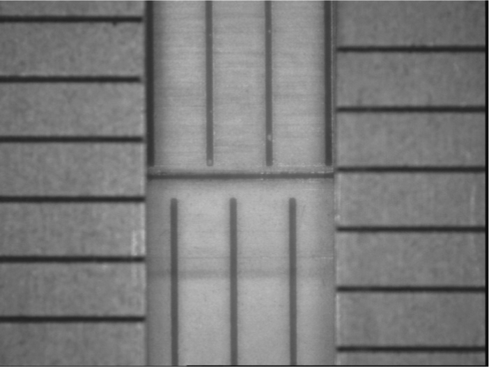
Ruler target plane image.
The measurement principle and obtaining static parameters
As described earlier, the host computer can process the sequence images of the ruler target scale acquired by the CCD imaging unit. The exact section diameter information of the current position can be obtained through image processing. 11 The axial displacement information can be measured by the circular grading mount at the axial displacement drive device. The static parameters such as volume, inflection point, taper and length of chamber can all be calculated through processing the axial displacement and diameter. We will describe the calculation of the parameters in this section.
Obtaining chamber diameter and depth
The cross-section diameter data are divided into two groups, and the final value of diameter is the mean of the two directions, so that the error is eliminated. The diameter is composed of the reference diameter and relative diameter. The cross-section diameter

where Di is the average diameter of the cross section i, Db is the reference diameter and ΔDi is the relative change between the diameter of the cross section and that of calibration ring, which can be expressed as

where

where

where

Calculating the chamber volume
According to the diameter and axial displacement of every measured section, the volume of every frustum can be calculated. The volume of frustum i can be expressed by
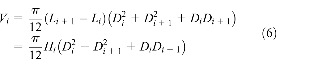
where Li is the axial-direction displacement of circular section i, Di and Di+ 1 are the upper and lower diameters of the frustum i. The volume of the chamber can be obtained by accumulation of the volume of each frustum
Calculation of inflection point and taper angle
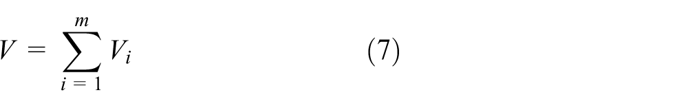
Because of the repeated bomb shooting, the inner wall of the chamber wears down seriously, the inflection and taper can be obtained by practical measurement. As can be seen from Figure 6, a kind of intersection of fitting lines is presented, in which the neighbourhood taper function can be obtained by line fitting and the inflection point is the intersection of neighbour line of 12 Si and S (i+1).
Calculation of inflection and taper angle.
Precision analysis of chamber parameters
There is error for any measurement system inevitably, so analysing the measurement precision is important to reduce the error.
Precision analysis of diameter
From equation (1) we can get
From the Bessel formula 13

For each measurement of the diameter, several parameters will affect the measurement accuracy. So, accuracy analysis is presented as follows:
Uncertainty of calibration ring manufacturing, which can reach
Uncertainty of sequence image processing, decided by optical and CCD camera, which is
In general, as shown in Figure 7, the image plane of CCD is not parallel to the target plane. Without loss of generality, the angle between the target plane and the image plane is θ, the current angle of view is

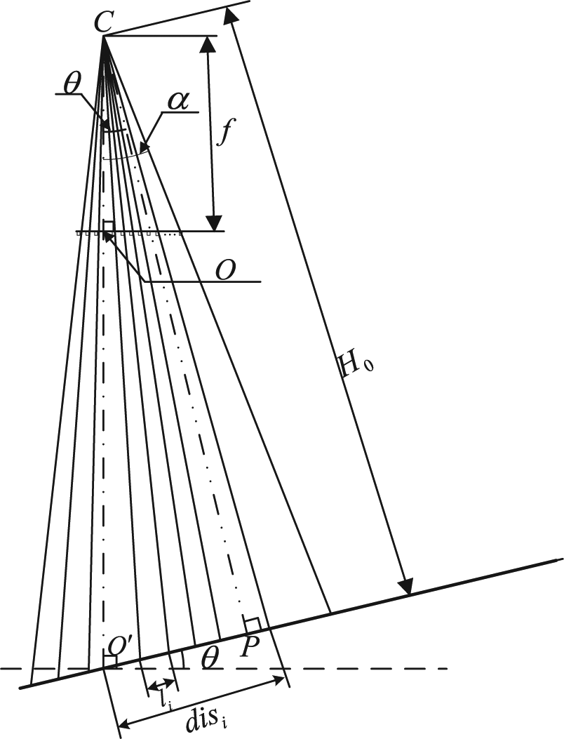
Camera imaging error by target plane non-orthogonal and pixels uniform.
It can be seen that the distance

According to the theory of error propagation, set
In general, θ is a small value, then

While
3. Incline of the target mechanism.
As can be seen from Figure 8, there is a small angle θ between the axis of the chamber and the measurement target because of the mechanical assembly. Assuming the taper angle is α, then we can obtain


Inclination of the measurement touch.
Then

Without a loss of generality, θ < 0.6°, α < 10° and AB < 200 mm; then
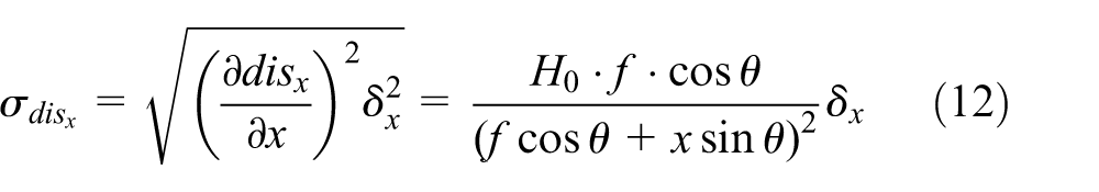
4. Un-centring mechanism
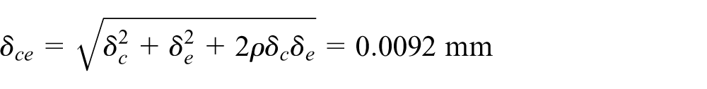
In general, 70 mm ≤ ϕ ≤ 200 mm, d ≤ 0.05, so |δe | ≤ 0.005 mm. Equation (16) also demonstrates that the cross-diameter measurement method can compensate the error of eccentricity of centre (Figure 9). We can assume the correlation coefficient is ρ = −0.5, so we can combine the error of δc and δe as

Eccentricity of centre for assistant centring.
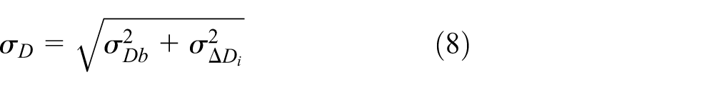
From earlier analysis, we can obtain the precision analysis of the diameter as

Precision analysis of volume
From equation (6) we know that

Taking a sub-set of data from the actual measurement, that is,

Then,
Experimental results
The measurement model machine is shown in Figure 10. The measurement claws are tested by the precise displacement device. In measurement, every measurement claw is calibrated by taking the high-precision grating scale as a calibration reference. As the test scheme shows in Figure 11, moving the measurement claw and grating by 30 mm, the displacement for the first and third rulers is drawn in Table 1, which shows that the measurement error is less than 10 µm for every measurement claw. This fact satisfies the requirements of the system.

Measurement system for chamber parameters.

Claw calibration experimental scheme.
Measurements of error of diameter direction cross claws for rulers 1 and 3 used in the model machine.

The upper computer software is realized by VC++6.0. The radial displacement of the diameter is drawn on the home screen as shown in Figure 12.

Home interface of the chamber parameter measurement system.
Discussion
From the precision analysis and experiments, we can find that the shorter the step, the higher the volume measurement precision. But short step means lower measuring efficiency. Therefore, the research of the self-adaption step measurement algorithm which is characterized by short step at inflection point and long step at smooth place can meet the necessary requirements for high precision and high efficiency. We can focus on the self-step measurement and high-resolution image measurement algorithm in the future research.
Conclusion
A kind of chamber measurement system based on machine vision is proposed through a research chamber measurement technique, and the system measurement precision is analysed. Experimental results on the prototype are presented. The system skilfully combined the image and scale targets, and the measurement values are obtained accurately, which provides a reference value for other similar systems with promising potential applications.
Footnotes
Academic Editor: ZW Zhong
Declaration of conflicting interests
The author(s) declared no potential conflicts of interest with respect to the research, authorship and/or publication of this article.
Funding
The author(s) disclosed receipt of the following financial support for the research, authorship and/or publication of this article: This work was supported by Science and Technology Research, Development Program of Shaanxi Province of China (No. 2013K09-17) and China Postdoctoral Science Foundation funded project (No. 2015M580805).