
Abstract
This article presents a cost-effective antenna design for wireless power transfer in electric scooters. The proposed design can be applied to any commercial 48 V/20 Ah electric scooter. In this study, based on the magnetic resonant coupling theory, a circuit that satisfies SAE J2954 specifications is presented. One-directional antenna/receiver pair is designed to meet the requirements of scooter-using scenarios. The transmitting coils are set up under the chassis of the scooter. The receiving coils are embedded in the bottom layer of the chassis, where the air gap between these two coils is larger than 10 cm. Based on SAE J2954 requirements, the operation frequency is tested around 85 kHz. Under proper power supply, the battery can be fully charged wirelessly and the system is user-friendly. The experimental results confirm the desired performance and feasibility.
Keywords
Introduction
Recently, due to the urgent charging requirement from consumer electronics, wireless power transfer (WPT) systems are becoming popular functions due to their convenience. The automotive industry is no exception, especially electric vehicles. Wireless charging technology can offer some conveniences to gain more user freedom in vehicle operation. Based on this prospect, this study proposes a circuit-designed WPT for electric scooters.
WPT is a power electronic technology that endows the consumer with a convenient power-charging experience. The WPT air gap is an important specification. The larger the air gap that is achieved, the more freedom one has in the application of WPT. Basically, the air gap can be treated as an index to classify the systems from their fundamental setup. Figure 1 shows three ways in which power can be transferred wirelessly. 1 Figure 1(a) illustrates the solution of magnetic flux induction, which is widely applied on power transformer. Only the inductor is utilized in the circuit for magnetic flux induction. This is a cost-effective construction for WPT when the air gap is less than 2 cm. Based on this configuration, the power efficiency is inversely proportional to the square of the air gap. Due to the fact that iron loss is proportional to the cube of power frequency, magnetic induction usually works on a low-frequency band, for example, less than 1 kHz. Figure 1(b) reveals the solution of magnetic resonant coupling, which is a high-efficiency, mid-distance approach. This configuration uses capacitors and inductors to build a frequency resonance and can achieve a higher air gap for applications. If the air gap is less than 2 m, this approach is competitive to other approaches. The suitable operating frequency of magnetic resonant coupling falls on the band of kHz and MHz. Figure 1(c) shows the solution of the electromagnetic wave. Based on the principle of Maxwell’s equations, the air gap can be wider than 8 m. Additionally, the operation frequency can achieve the band of GHz; however, its trade-off is electromagnetic radiation. Very high frequency of certain waves, such as microwaves, is harmful to human health, especially in high power transfer. Consequently, cost-effective implementation with safe operation is desired and expected. Nowadays, electromagnetic radiation is considered as a harmful source. Conversely, the solutions of Figure 1(a) and (b) use merely the magnetic flux to carry the energy. Only the ferrite materials can achieve an interaction on it. Consequently, these two approaches are harmless to human body. Until now, high-power WPT is still the bottleneck of these three aforementioned approaches.

Three ways of wireless power transfer: (a) magnetic flux induction, (b) magnetic resonant coupling, and (c) electromagnetic wave.
Figure 2 shows the frequency band of different applications. In order to avoid the interference of each application, the law should be established first, for example, the bandwidth and human health regulations. In order to use the frequency effectively, some organizations have set up the corresponding standard to control the operation, such as IEC 61980 series, ISO 19363, SAE J2954, and UL2750. In order to build a wireless charging system for electric scooters, the frequency requirement is the first issue. For vehicle applications, the SAE (Society of Automotive Engineers) surveyed laws and safety and published the standard SAE J2954 2 in 2013. SAE J2954 suggests all of the requirements for WPT for all types of electric and plug-in hybrid vehicles. Of course, the electric scooter is an application. Now, the SAE J2954 is accepted as the WPT standard for electric vehicles. The SAE announced SAE J2954 in 2013, which designates 79–90 kHz being the main band of WPT for electric vehicles, plug-in hybrid, and hybrid vehicles. Its central and designated frequency is 85 kHz, which is a challenge for practical implementations. The novel option proposed herein is to design a WPT system with a circuit that can be fabricated merely using power electronic devices, such as the metal–oxide–semiconductor field-effect transistor (MOSFET) or insulated gate bipolar transistor (IGBT). Compared to the higher frequency system, such as 13.56 MHz, 3 the amplifier is unnecessary.

Frequency band of different applications.
Investigations on WPT for mid-distance air gap configuration are ongoing. For instance, Kurs et al. 4 employed magnetically coupled resonators to achieve a 60-W lump lighting within a distance of 2 m in 2006. In their approach, the resonant frequency is 9.9 MHz. Ahn and Kim proposed a WPT approach for a bus system, namely, “on-line electric vehicle (OLEV)” 5 in 2011. Unlike the magnetic resonant approach, their method achieved 100 kW charging using the magnetic induction methodology. The transmitter antenna is set up under the road level, and the receiver antenna is set up in the bottom of the vehicle’s chassis. In order to harvest as much as of the magnetic flux as possible, this approach employed the ferrite core as the flux carrier. Consequently, the iron loss is really high in this system. Subsequently, many studies have been inspired to build an OLEV-like system. Additionally, there has been a push to improve the system efficiency. For example, Onar et al. 6 investigated covering loss of different materials, which is between the air gap and antenna. In addition, their investigation reports that the aluminum sheet can prevent certain flux disturbance.
To carry out the high-power WPT in a large air gap (at least 10 cm), the magnetic resonant coupling, which is called the nonradiative scheme, is an effective and famous approach. Basically, it is an LC resonant circuit. Unlike magnetic induction, which transfers power merely based on inductor coils, the LC resonant circuit can sustain the same efficiency with a higher air gap. Figure 3 shows four basic circuit patterns of LC magnetic resonant coupling. According to the investigation in Ni et al., 7 the parallel topology has more advantages on heavy load. In this study, the major circuit scheme is in parallel–parallel type, which satisfies the specification of SAE J2954.

Four basic charing patterns.
Due to the fact that niche competition on electric scooters is keen and low, the proposed design can enhance electric scooter. However, the cost will not increase significantly. In this article, an innovative antenna design is presented that offers new prospects for the WPT system. Its scheme is the same as the technology from magnetic resonant coupling. Details of this methodology will be discussed in the following sections.
Principle methodology
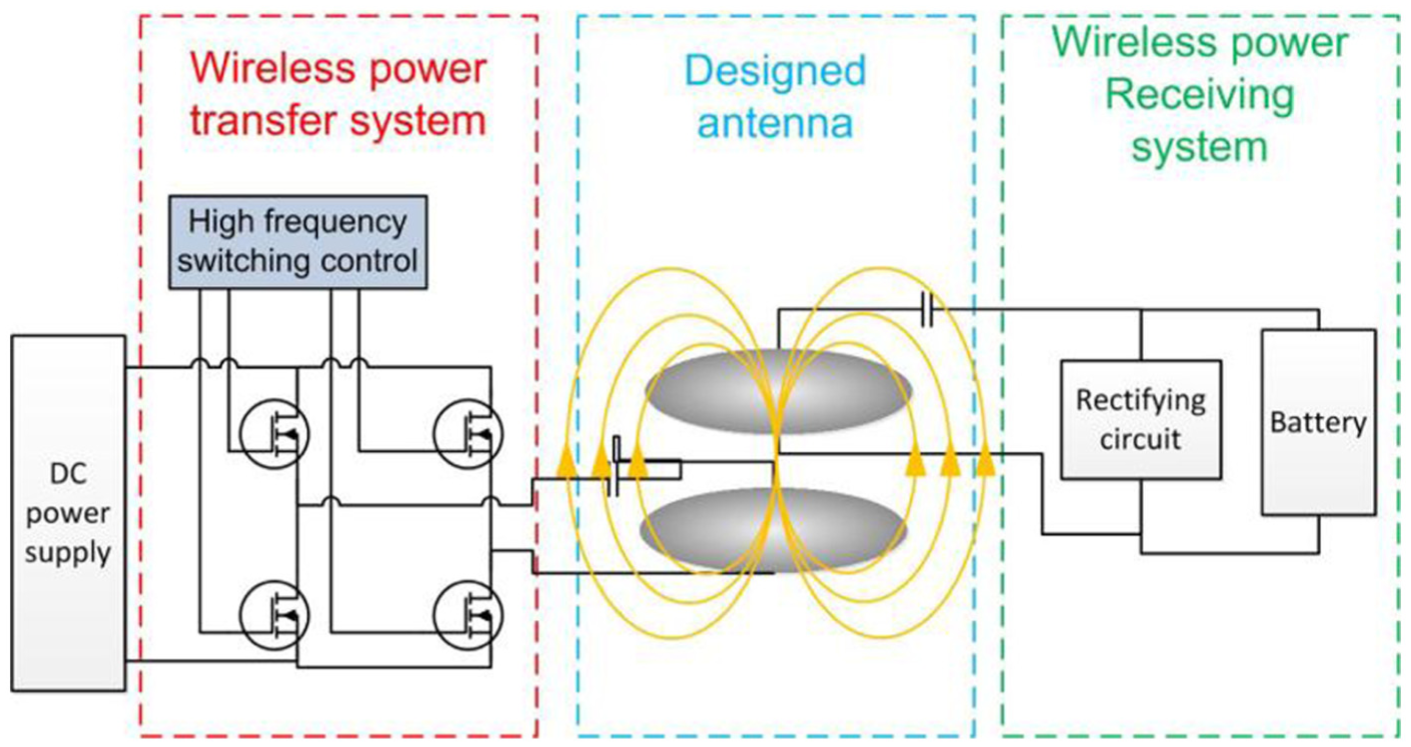
As shown in Figure 4, the proposed system is implemented on a prototype electric scooter, namely, Super Mini. The specifications of Super Mini are given in Table 1. It exploits the same setup as OLEV for stationary charging. The transmitter coils are set up under the ground, and the receiver coils are embedded in the bottom layer of the chassis. This setup does not have positive/negative pole problem. In addition, it is waterproof, emits no radiation, and it is not easy to get an electricity shock. Figure 5 shows the presented system scheme for WPT on electric vehicles/scooters. As it can be seen in this figure, this is a magnetic resonant coupling approach. Consequently, the impedance matching of LC becomes an important issue. Under proper impedance matching, the frequency and efficiency can achieve the specific design goals. 8 Therefore, the battery on electric scooters can achieve a quick charge effectively.

Prototype scooter: Super Mini.
Specification of the experimental scooter.

System configurations.
This approach is based on the foundation of near field communication. Its kernel technology is power electronics. The whole system utilizes purely the magnetic field to carry and transmit the energy. Consequently, no harmful radiation exists. Under this setup, the quality factor Q is an important parameter. 9 It stands for the ratio of stored energy and dissipated energy of an inductor as shown below
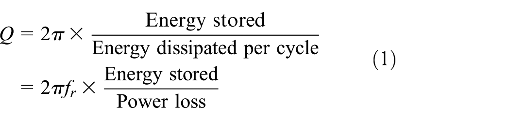
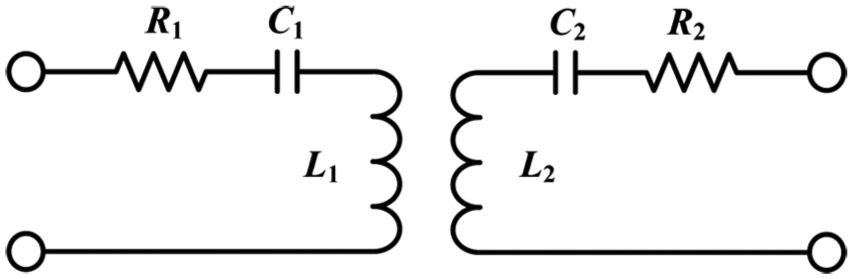
The quality factor Q can be affected by the coil material, coil size, and coil impedance. If the Q factor is high, the loss is low and efficiency is high in consequence. Therefore, in the circuit design of the presented system, the Q factor can be an index. Figure 6 shows the equivalent circuit of magnetic coupling. Obviously, one can obtain

because


Equivalent circuit of magnetic coupling.
Solving equation (3), one has

where
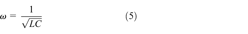
Equivalently,

Clearly, the impedance matching of RLC parameters plays an important role of dominating the oscillation frequency and transmission efficiency. Considering the power and efficiency issues, Figure 7 shows a related series circuit for WPT. Similarly, the operation frequency is same as the resonant frequency

Series circuit configuration of wireless power transfer.
From Kato et al., 10 one can have the voltage ratio as

The efficiency
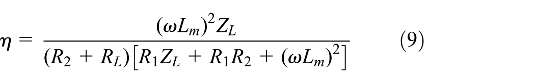
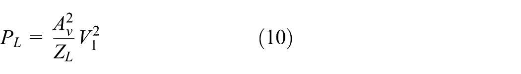
From equations (9) and (10), it is clear that

and

Transmitter and receiver system
Figure 8 shows the charging scenarios of the proposed system, and Figure 9 illustrates the relevant circuit. The main circuit is revealed in Figure 9(a), and Figure 9(b) is the operational current direction. In practice, the air gap is set from 10 to 15 cm. The shorter the air gap, the larger the charging current that can be obtained. As it can be seen in Figure 9, the frequency switching device can be carried out by common power electronics, such as the MOSFET or IGBT. The main purpose of this circuit is to build an 85-kHz sinusoidal oscillator. In this article, we utilized the parallel–parallel structure to construct the circuit. Moreover, we utilized the transmitter/receiver to transfer the power to the rectifier and then charged the battery wirelessly. The difference between the proposed circuit and the conventional approach is that the presented approach can trigger a self-oscillation of 85 kHz. However, most of the conventional approaches need an external function generator. Obviously, the proposed approach is convenient and cost-effective. Additionally, the advantage of this study is the inductor value for transmitter can be small, allowing the capacitance value to be more easily tuned based on the requirement of impedance matching. Figure 10 shows the waveform between the input and output side of a diode.

Proposed scooter system.

Schematic circuit: (a) main circuit and (b) operational current direction.

Waveform between a diode.
Receiver design of WPT is a crucial issue. It greatly affects the efficiency and the air gap. Based on SAE J2954, the oscillation frequency is 85 kHz. Consequently, most of the consumer AC-to-DC converters are not usable for rectifying and charging. Therefore, how to receive the magnetic energy and charge the energy to the battery becomes a challenge. Figure 11 shows two solutions employed in this article. Figure 11(a) is well-known bridge rectifier with a DC-to-DC converter. Figure 11(b) is an alternative and cost-effective approach. First, the current charges the capacitor, and second, the capacitor charges the battery.

Receiver circuit: (a) bridge rectifier with a DC-to-DC converter and (b) capacitor with diode.
For experiments, the proposed system is first evaluated on a plate antenna. Figure 12 shows the system setup, where Figure 12(a) is the plated antenna of the receiver and Figure 12(b) is the transmitter and electric scooter. Figure 13 shows the experimental results of WPT. Using the self-oscillation approach, the receiving DC current can reach 1.5 A. Consequently, the 1-kWh battery can be charged from SOC (state of charge) 20% to 80% within 8 h.

Experimental setup: (a) plated antenna and (b) transmitter and electric scooter.

Experimental results of receiving current.
Directional antenna design
In the experiments, we found that the antenna plays a role relative to the efficiency and air gap. Figure 14 shows a common type of coaxial coils. For a conventional approach, both the transmitter and receiver coils are in this shape. In order to improve the efficiency and enlarge the air gap, this article proposed the directional antenna pair as shown in Figure 15, where Figure 15(a) is the transmitter and Figure 15(b) is the receiver. In this article, the system belongs to the magnetic resonant coupling. Hence, the iron core for flux concentration is not needed. Figure 16 shows the three-view diagram of the proposed transmitter. Figure 17 reveals its experimental results. The air gap in this experiment is 5 cm, and a 100-W lamp was employed as load for performance evaluation. As it can be seen in Figure 17(a), the lamp is off because the transmitter antenna is pointed toward the receiver from the back. Figure 17(b) shows that the lamp is on because the transmitter antenna is pointed toward the receiver from the front. Figure 17(c) shows that the system is operated around the frequency of 85 kHz. Obviously, the directional performance of the antenna design reveals an acceptable result.

Coaxial coils: (a) transmitter and (b) receiver.
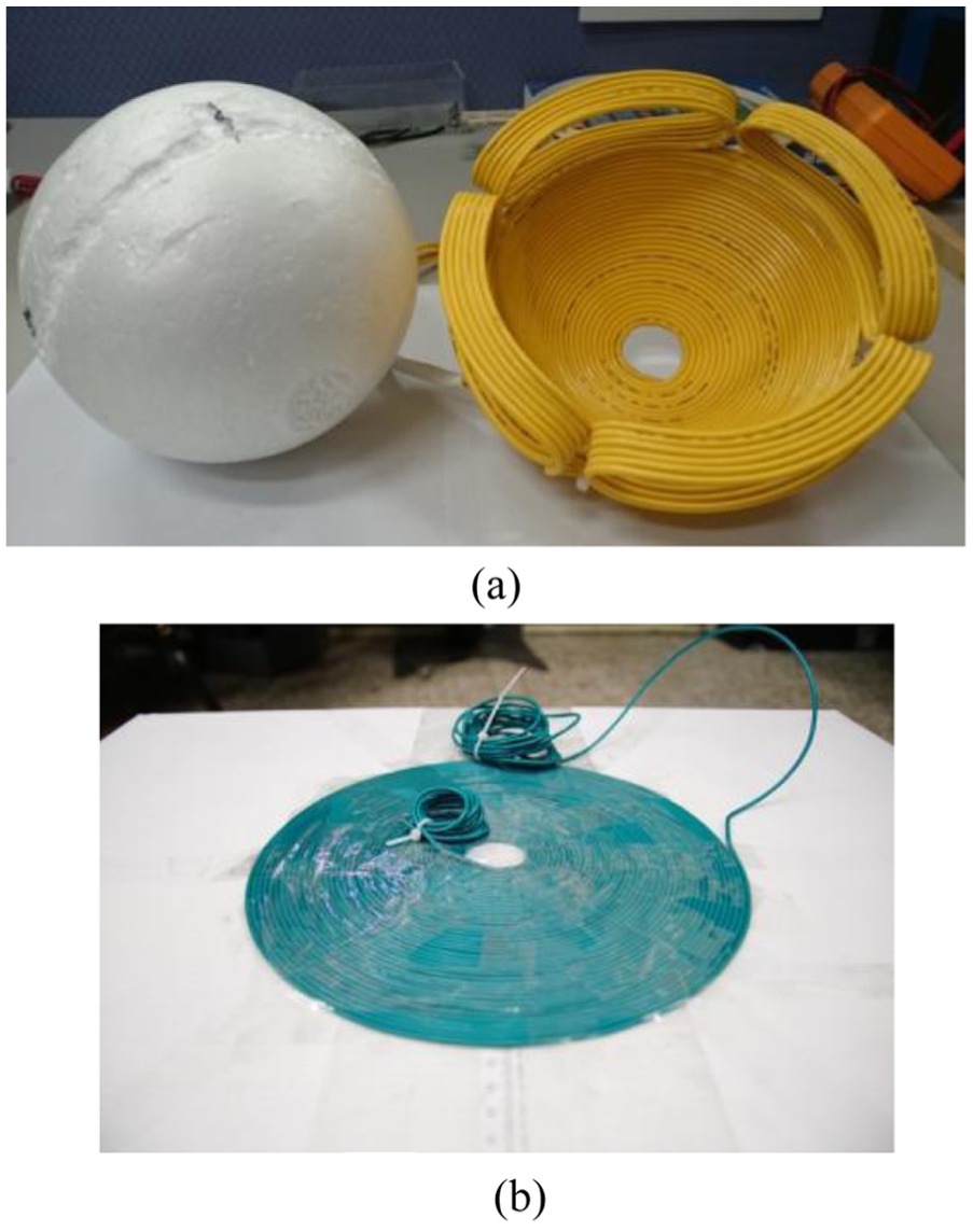
Directional antenna: (a) transmitter antenna and (b) receiver antenna.
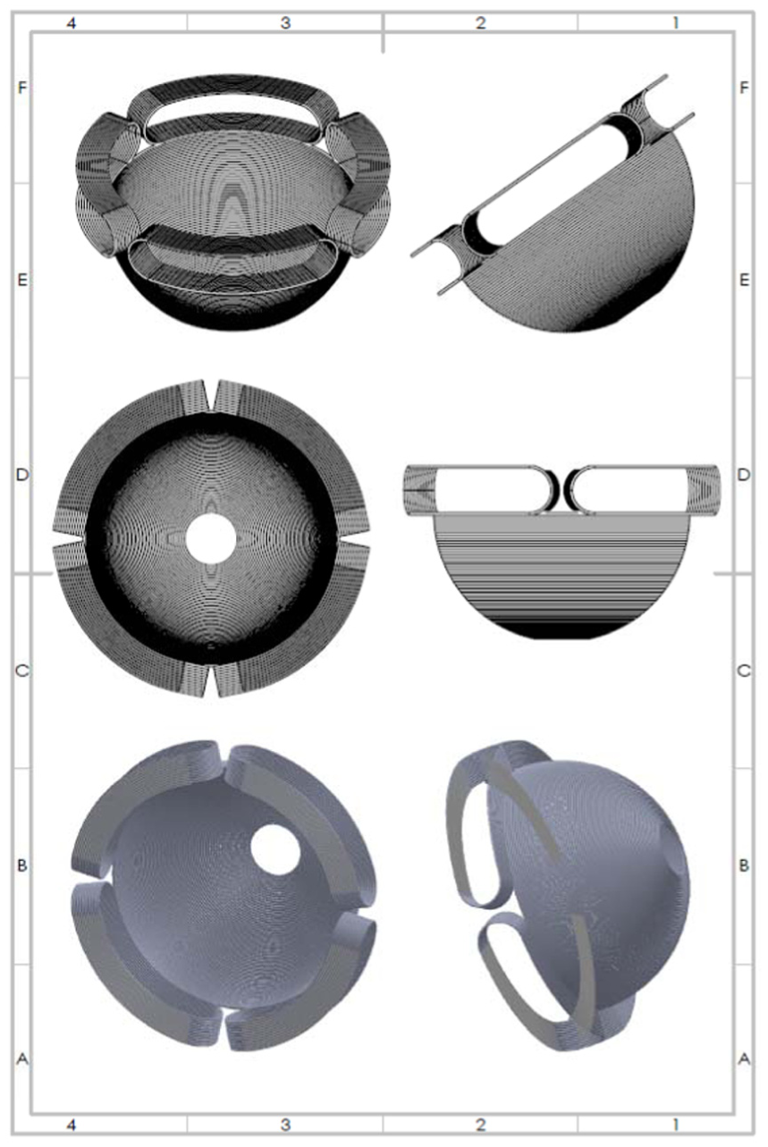
Three-view diagram of the proposed transmitter.

Experimental results of directional antenna: (a) back side toward the receiver: the lamp light is off, (b) front side toward the receiver: the lamp light is on, and (c) the operation frequency of 85 kHz.
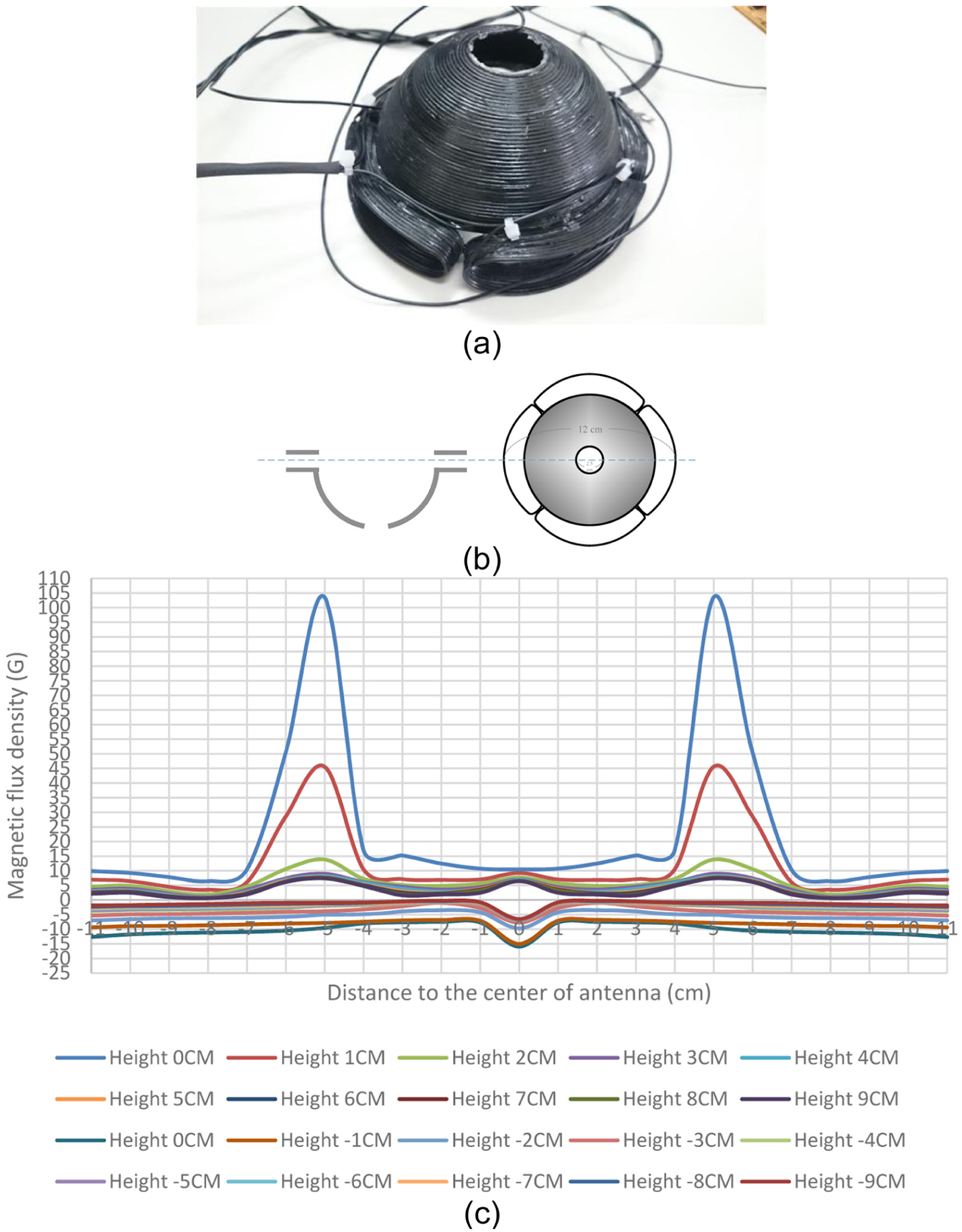
In order to obtain the flux distribution of the proposed design, three types of antennas were employed for comparison. The following Figure 18 shows the measurement setup. Figure 18(a) displays the SYPRIS Model 7030 GAUSS/TESLA meter, and Figure 18(b) illustrates the coordinate setup for the reference frame. Figures 19–21 give three types of antennas: plate type, pipe type, and proposed directional design. Part (a) of these figures is the appearance of the antenna; part (b) is its relevant dimensions; and part (c) is the measured results of flux distribution. Note that in Figure 21(c), the negative flux density stands for the flux which goes to the downward direction in the center area. Additionally, in the experiments of Figures 17–19, the air gaps are tested from 0 to 10 cm. For the scenario of electric scooter charging, the air gap is always under the condition of 10 cm. From these experimental results, obviously, the proposed design reveals a higher flux density to the receiver side than the other design. Consequently, this design can increase the distance of the air gap; hence, it is very suitable for use in the electric scooters to address its high chassis problem.

Measurement setup: (a) Gauss meter and (b) coordinate setup for reference frame.
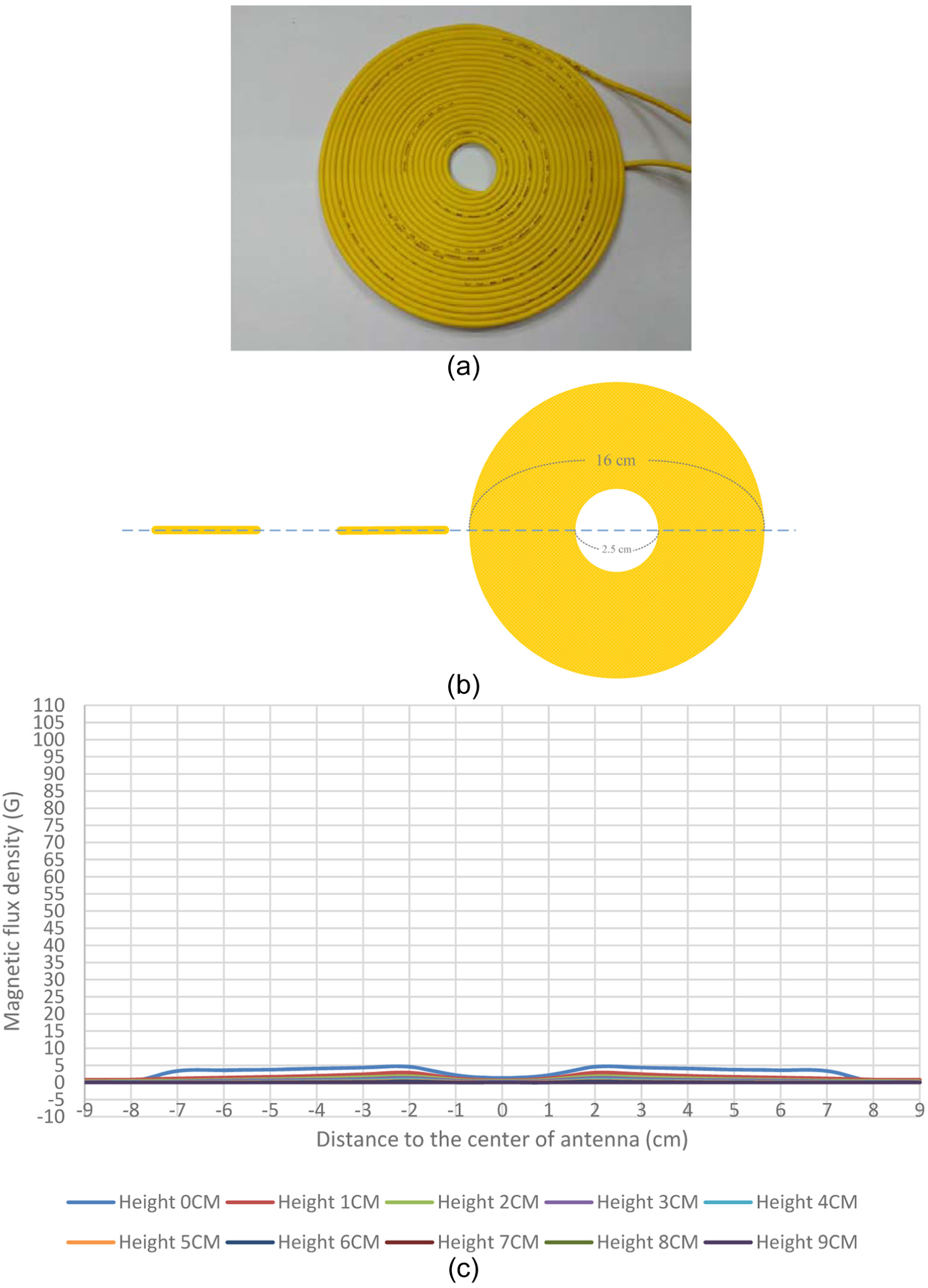
Experiments of plate-type antenna: (a) antenna appearance, (b) antenna dimensions, and (c) measured results of flux distribution.

Experiments of pipe-type antenna: (a) antenna appearance, (b) antenna dimensions, and (c) measured results of flux distribution.
Experiments of the proposed directional antenna: (a) antenna appearance, (b) antenna dimensions, and (c) measured results of flux distribution.
Note that the efficiency of the proposed WPT mainly depends on the circuit impedance matching. The three-dimensional (3D) directional antenna design can increase the distance of the air gap. However, it also leaves the drawback of the impedance matching problem. Based on SAE J2954, the circuit inductance is determined by the antenna; then, the capacitance of the circuit should be selected to the resonant value. In practice, this matched value of capacitance is sometimes not easy to obtain. Consequently, the automatic impedance matching circuit leaves an interesting issue for future investigations.
Conclusion
In this article, a cost-effective design on WPT for electric scooters has been proposed. The proposed design can be applied to any commercial 48 V/20 Ah electric scooters. Based on the magnetic resonant coupling theory, a circuit that satisfies the specification of SAE J2954 has been presented. Additionally, in order to improve the transmission efficiency, a directional antenna design was presented. From the experimental results, the proposed directional antenna design reveals a higher flux density to the receiver than the other counterpart. Consequently, this design can increase the distance of the air gap; hence, it is very suitable for use in the electric scooters to address its high chassis problem. However, it also leaves the drawback of the impedance matching problem. Based on SAE J2954, the circuit inductance is determined by the antenna; then, the capacitance of the circuit should be selected to the resonant value. In practice, this matched value of capacitance is sometimes not easy to obtain. Consequently, the automatic impedance matching circuit leaves an interesting issue for future investigations.
Footnotes
Academic Editor: Stephen D Prior
Declaration of conflicting interests
The author(s) declared no potential conflicts of interest with respect to the research, authorship, and/or publication of this article.
Funding
The author(s) disclosed receipt of the following financial support for the research, authorship, and/or publication of this article: This work was supported by the Ministry of Science and Technology (MOST) of Taiwan, under projects MOST 103-2622-E-024-005-CC2 and 104-2622-E-024-003-CC2.