
Abstract
A numerical methodology has been developed to simulate the overall ablation process of the insulator material named ethylene-propylene-diene monomer. Special attention is focused on the char layers of ethylene-propylene-diene monomer formed in different ablation environments by analyzing the characters of the char layers, which was defined as an uneven porous medium. An overall ablation model has been developed to describe the simultaneous thermo-chemical ablation and particle erosion of ethylene-propylene-diene monomer using porous medium equation methodology. A total of six calculations of one kind of ethylene-propylene-diene monomer material have been performed to obtain the theory erosion properties in two lab-scale solid rocket motors, and all the submodels of overall ablation model have been validated.
Introduction
Interior insulator is an essential component of solid rocket motor (SRM) to withstand the high temperature, high pressure, and two-phase combustion gas erosion condition. At present, ethylene-propylene-diene monomer (EPDM) is widely used as matrix of insulator in SRM for its low specific density, high thermal stability, great char yield, and excellent mechanical properties.1–4 In order to reduce the negative mass and improve the integral design level of SRM, many numerical methodologies have been developed to model ablation process when insulator material is exposed to high temperature, high velocity, and particle-laden gas conditions. However, the ablation process of EPDM is very complicated, which includes heat conduction, pyrolysis, and carbonization, thermo-chemical reaction, mechanical erosion, and so on. Furthermore, the interaction effect between thermo-chemical reaction and mechanical erosion will take place, namely, the particle impact augment thermo-chemical ablation and thermo-chemical assist mechanical erosion. To evaluate the ablation behavior of EPDM materials, overall ablation model is needed to describe the ablation process accurately. Mockenhaupt and Wickman 5 and Chiba and Beck 6 have developed an overall material ablation model for reentry vehicle erosion. In this model, thermo-chemical ablation occurs at the surface of the char layer, and the particle impact effect only caused mechanical erosion.
In order to predict the ablation characteristics of fiber-reinforced polymer composites used in interior insulator, a transient, two-dimensional overall ablation model was proposed by Yang et al. 7 In this model, the homogeneous thermo-chemical ablation was assumed in the char layer, and the particle impact effect was described as heat laden and mechanical erosion.
In fact, the char layer of polymer-based insulator material after firing test is crispy and uneven,8,9 so it is easy to peel off under particle-laden flow condition. However, most of the overall ablation models focus on the constant properties of the char layer.
In this article, char layer microstructure of EPDM formed under different ablation environments was analyzed. Based on the porous structure of the char layer, an innovative overall ablation model has been developed for predicting the ablation behavior of EPDM in SRM.
Experiment and ablation model
Experiment configuration and material
To understand the ablation mechanism of EPDM, two lab-scale SRM hot firing systems are utilized to generate different ablation environments. The SRM-I shown in Figure 1 mainly consisted of combustor, solid propellant, test section A, test section B, convergent section, and nozzle. The double-based propellant coated by inhibitor layer is loaded in combustor to generate pure gas condition. The EPDM specimens are mounted in a concave steel anvil which is set up on the test sections A and B. The cross-sectional area of section A was designed larger than segment B to realize different gas velocity on the surface of the insulator specimens. During the operation of SRM-I, the high-temperature gas releases from the propellant-burning surface, and a constant pressure is maintained. In this article, the gas temperature is 3016°C, and the pressure of the chamber is 6 MPa.

Schematic diagram of the hot firing test SRM-I.
The SRM-II is designed to generate condensed particle erosion condition, the composite propellant containing 17% Al is used to produce high-temperature, particle-laden gas flow, the temperature of combustion gas is 3147°C, and the pressure of the chamber is 6 MPa in this article.
As shown in Figure 2, SRM-II is composed of combustor, solid propellant, convergent section, adjustor, test section, nozzle, and so on. The sliced EPDM insulator specimen is set up in the bottom of test section. By changing the diameter of adjustor and angle of test section, the different particle erosion environments, including particle impact velocity, concentration, and angle, can be simulated.

Schematic diagram of the hot firing test SRM-II.
To obtain the particle erosion parameters in different experimental conditions, the three-dimensional two-phase flow is simulated by solving the Reynolds-averaged Navier–Stokes equations, including the interphase coupling terms of the continuous phase and the discrete phase described by the Lagrangian method using the Fluent software. 10 The Renormalization Group (RNG) k–ε model is applied to predict the turbulence of the flow, and the influence of turbulent dispersion on particle motion is considered using stochastic tracking model. Solid walls which include specimen surface are all of no-slip type and adiabatic. The particle size distribution measured in SRM is employed. 11 Based on the real geometry of the small lab-scale SRM hot firing test motor (Figures 1 and 2), the three-dimensional two-phase flow detailed flow field is simulated. The user-defined functions are used to calculate particle impact properties on the surface of EPDM specimen.
The gas components of propellant used in the SRM-I and SRM-II are obtained by CEA software. Table 1 lists the oxidation component mass fraction of CO2, H2O, and O2 which attack the char layer.
Mass fraction of CO2, H2O, and O2 of gas.
In order to evaluate the accuracy and demonstrate the applicability of this numerical approach, numerical calculations have been made for simulating the properties of one kind of EPDM insulator in SRM-I and SRM-II. The EPDM insulator is composed of 70% EPDM, 10% Kevlar, 8% ZnB, and 12% SiO2; and the pyrolysis heat of formation is 337 kJ/kg. The physical properties of EPDM are shown in Table 2.
Physical properties of EPDM.

EPDM: ethylene-propylene-diene monomer.
A JEOL JSM-5800 scanning electron microscope (SEM) is used for morphological investigation and energy dispersive spectroscopy (EDS). The porosity and specific surface of the char layer are measured by porosity instruments. The pyrolysis parameters of EPDM insulator is obtained by differential scanning calorimetric (DSC) meter. The main ingredients of decomposition gas are identified by HP-5890GC/5972MSD gas chromatograph–mass spectrometer (GC-MS). Table 3 reports the main ingredients of decomposition gas of EPDM.
Main ingredients of decomposition gas.
Ablation rate represents the ablation properties of insulator materials and is defined as the virgin materials recession rate of the materials, but it is hard to obtain accuracy surface recession rate in tests because the char layer is crispy and easy to break. Therefore, the test ablation rate is defined as the thickness of test material in this article.
Ablation process analysis and characteristics of the char layer
The char layer of polymer materials is the barrier to the high heat flux of gas and particle laden, so the properties of the char layer are very important to the ablative properties. Thermo-chemical ablation consumes the char layer and weakens the char layer, and particle erosion peels off the weakened char layer, so char layer is the hinge to the coupling mechanism of thermo-chemical ablation and particle erosion.
The char layers of EPDM obtained from experiments were scanned with electron microscope. Figure 3 shows the SEM images in the cross section of the char layer under different ablation environments. Figure 3(a) shows the char layer obtained in test section A of SRM-I with pure combustion gas, particle concentration

Images in cross-sectional morphologies of the char layers in different erosion conditions: (a) ρp = 0, Vg = 2.4; (b) ρp = 49.6, Vp = 31; and (c) ρp = 54.9, Vp = 36.
By analyzing the micrographs of the char layers and testing the porosities and elemental composition of all char layers, common characteristics of the char layer structure in these three tests have been discovered: (1) the char layers are loose and uneven; (2) the average porosity is between 70% and 80%, and >90% pores inside the char layer are connected with other pores; and (3) the main elements of the char layer are C (>80%), O (>15%), and Si (<5%). Based on the above characteristics, the char layer can be described as gas-saturated uneven porous medium, and the compact structure and loose structure exist in the char layer. Because the pores inside the char layer are interconnected, the gas can diffuse inside the char layer, and the chemical reactions not only occur on the surface of the char layer but also occur inside the pore of the char layer, so the chemical reactions will change the porosity matrix of the char layer, decrease the strength of the char layer, and assist the particle mechanical erosion.
The compact structure marked with line in Figure 3 is ubiquitous in the char layers, and the compact structure in the char layer would offer a higher resistance to the impact of mechanical erosion, so the forming of compact zone should be considered. Many experimental results show that the primary reason of the compact layer formation is the chemical vapor deposition (CVD) of pyrolysis gas in the char layer under certain temperature range. 8 Because of the different heat fluxes on the surface of the char layer and different gas temperatures in different ablation environments, under the couple effects of heat conduct, pyrolysis, and carbonization of insulator, the position and thickness of the compact layer is determined by temperature distribution and mass flux of decomposition gas. To describe the process of overall ablation process accurately, the diffusion of pyrolysis gas and CVD must be considered.
Particle impact enhanced the heat flux and mechanical erosion effect on the char layer. The heat flux of particle impact (
The research of the char layer surface porous characteristics under different particle erosion conditions shows that 13 the porosity of the char layer can indicate the structure strength of the char layer. The greater the porosity in the char layer, the easier the char layer can be peeled off. Therefore, the critical strength of the char layer can be used to describe whether the char layer can be cut off under certain particle erosion parameters. 14
By analyzing the surface images of the char layer in different particle impact conditions in Figure 4, the surface porosities decrease with the increase in the particle erosion strength; the smaller the surface porosity, the stronger the particle effect, so the surface porosity of the char layer can be used as critical strength factor

Images in surface morphologies of the char layers in different ablation environments: (a) ρp = 49.6, Vp = 31, αp = 29°; (b) ρp = 54.9, Vp = 36, αp = 24°; and (c) ρp = 63.6, Vp = 42, αp = 45°.
When the surface porosity of the char layer is greater than the critical value
The particle erosion is coupled with thermo-chemical by particle heat flux, which accelerates the heat conduction inside the material, and the critical porosity
Ablation physical model
The overall erosion is described in Figure 5. During the ablation process, the ablative material is divided into three different layers: char layer, pyrolysis layer, and virgin material.
Schematic description of thermo-chemical ablation and particle erosion phenomena.
The description of the virgin materials and pyrolysis layer is the same as original ablation model, 16 and the new ablation model considers the effect of porous characteristics of the char layer. The combustion gas diffusion and pyrolysis gas advection take place in the char layer. The chemical reactions occur on the surface and inside the pores of the char layer and consume mass of the char layer. The compact structure is formed where the temperature T > Ts (Ts is the critical temperature of pyrolysis gas sedimentation), 17 and the loose/compact structure is formed. When the strength of the char layer cannot resist the particle impact, surface recession occurs. The strength of the char layer is represented by the porosity of the char layer.
Mathematical description of overall ablation model
Heat conduction
Heat conduction equations in the pyrolysis layer and virgin material are in the forms of equations (2) and (3)


where
The mathematical heat transfer in the char layer is described using energy equation for porous media

Gas diffusion
In order to calculate gas diffusion in the char layer, component conservation equation of gas is used in the governing equation system as follows

where
Pyrolysis
Pyrolysis governing equation is as follows
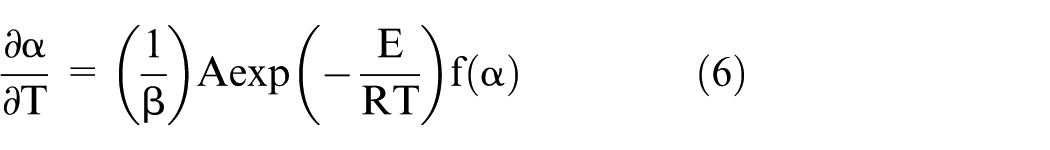
where
For the EPDM insulator in this study, its pyrolysis mechanism function is described as follows
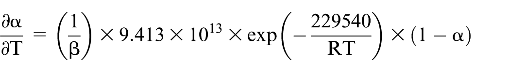
When T ≥ Tc, initial porosity of the char layer is calculated by equation (7)

Chemical reaction
Oxidation components reacted with the element of the char layer such as C and Si to consume the char layer. By testing the element content of the char layers, it is found that >80% is C and <5% is Si, so the chemical reactions consuming C considered in thermo-chemical ablation are as follows

The mass loss due to the above three chemical reactions is 17
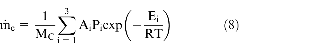
where

The heat source term

where

where
Distribution of porosity of the char layer is changed by chemical reactions, and it can be calculated based on the conservation of mass, and the new porosity

where
Compact structure
The mechanism of the compact structure formation in the char layer is considered as the sediment of the pyrolysis gases. But the sediment process is the combination of physical and chemical processes, and it is too complicated to describe by an accurate numerical model, so a simple numerical method is developed to simulate the formation process of the compact structure in the char layer by referencing from the mechanism of CVD and the experimental results. To facilitate this complicated problem, the following physical assumptions are employed:
The porosity in compact structure is constant and equal to
The critical temperature Ts 18 to form compact structure is equal to the temperature to fulfill the deposition of morphology.
The iterative procedure for compact structure formation is shown in Table 4.
Sediment simulation procedure.

Boundary condition
The boundary condition of erosion surface is the third kind of boundary condition.
The surface is classified into three kinds:
Before the material is decomposed

Surface is the pyrolysis layer

Surface is the char layer


When the porosities of portion of the char layer are larger than the critical porosity (
Numerical solution
In the present method, the fundamental equations are equations (2)–(5). Note that equations (4) and (5) have an unknown parameter

Flowchart of solution procedure.
Results and discussion
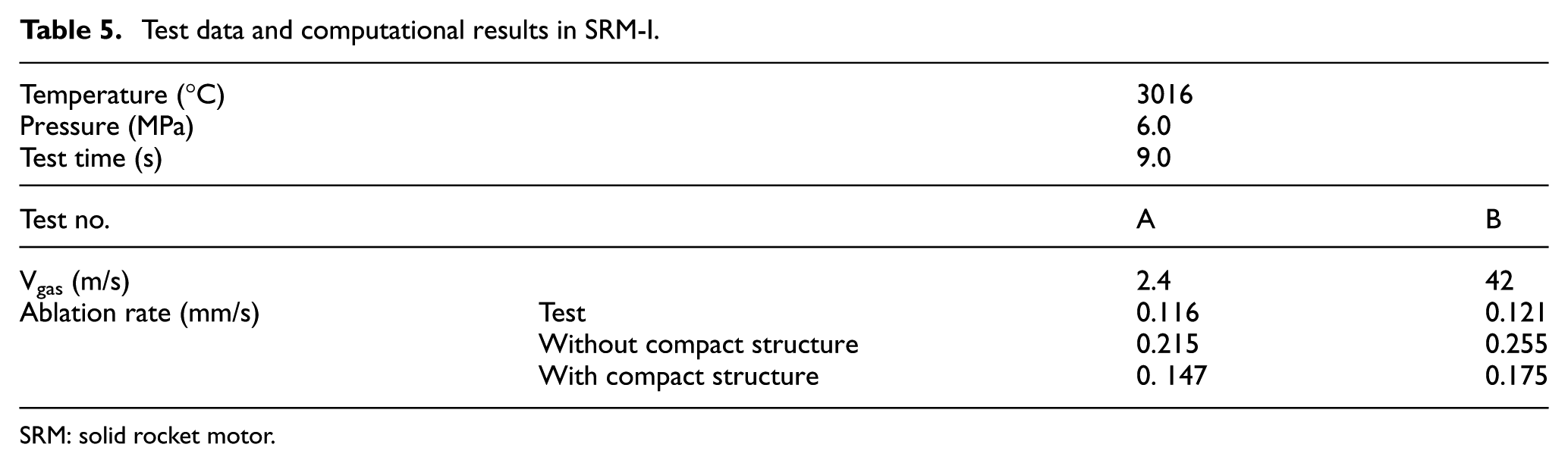
Experimental conditions, test results, and calculated results of SRM-I are shown in Table 5. Calculations A and B predicted the tests in SRM-I to evaluate the accuracy of thermo-chemical model. Based on the ablative motor with variable gas velocity, ablation experiment was conducted to investigate structure characteristics of the char layer of EPDM insulator in aluminous gas environment, and the char layer of insulator was analyzed by means of SEM and EDS. The results show that the char layers on the surface, back-face, and side-face have different patterns and porosities at different gas velocities; when gas velocity rises, the thickness of the char layer is decreased obviously, and the quantity of Al and Si oxide deposits on the surface of the char layer becomes more, loose degree increases, and structure intensity weakens. The experimental results show that when the gas velocity is beyond 60 m/s, the shear damage to the char layer is evident, while when the gas velocity is >60 m/s, the gas mainly enhances the heat transfer and thermo-chemical reaction, and the erosion effect is negligible. 9 The macro ablation rates in Table 5 also support the above result.
Test data and computational results in SRM-I.
SRM: solid rocket motor.
There are two groups of calculated results in Table 5 to evaluate the compact structure simulated method. The first group is the results calculated without compact structure simulated method, and the second group is the results calculated with compact structure simulated method, and the two results are compared with test data. Clearly, the accuracy of calculation considering the compact structure formation of the char layer is greatly increased. The error of ablation rates between the test results and calculated results is 0.054 mm/s, and the calculated results agree well with the experimental results; the compact structure numerical method is available in the model.
Calculations C–F predicted the coupled ablation process in SRM-II. The erosion model can be evaluated. The experimental conditions, test results, and numerical results are shown in Table 6. Each input condition is calculated with two results considering the particle heat flux for erosion boundary. The first group of results is calculated without considering the particle mechanical effect, and the char layer is only consumed by the chemical reaction; critical porosity
Experimental conditions, results, and numerical results in SRM-II.

SRM: solid rocket motor.
In Table 6, all the calculated ablation rates without the particle mechanical effect are lower than the test results, and the error is increased by the increased velocity and density of particle, such as the test no. F; the test result is three times of the first calculated result. The results considering the particle effect agree well with the test results, and the average relative error is 5.9%, and the accuracy of the procedure can fulfill the requirement for predicting the erosion properties of EPDM.
Figures 7 and 8 show the typical calculated porosity distributions of the char layers in SRM-I and SRM-II. The char layer is between the gas phase and virgin material. The porosity distribution of Figure 7 is the result of calculation A. The experimental char layer structure is shown in Figure 3(a), the surface of the char layer is compact structure, and no surface recession occurs. Compare the porosity distribution and the morphology of the char layer after hot firing test; the calculated char layer structure is in accordance with the test photograph. Figure 8 shows the porosity distribution of calculation C in SRM-II, Figure 3(b) is the test structure of the char layer of calculation C. Because particle effect increases the heat flux of the boundary and the mass surface recession rate, the char layer is formed as loose/compact structure, which is consistent with the SEM images of the char layer in Figure 3(b). So, the erosion mechanism of this erosion model can better simulate the production and consumption of the char layer. This is valuable for the particle erosion because in certain particle impact condition, the main factor to influence the particle mechanical effect is the structure strength of the char layer.

Porosity distribution of the char layer in SRM-I.

Porosity distribution of the char layer in test SRM-II.
Conclusion
The numerical model for overall ablation of EPDM material, including the particle erosion and thermo-chemical ablation process, has been presented. The structure of the char layer has been defined as the ligament to couple the thermo-chemical ablation and particle erosion. The char layer of ablative materials is treated as porous media, with chemical reaction and pyrolysis gas sediment occurring inside the porous of the char layer, and the loose/compact structure of the char layer is formed during ablation. Particle erosion effects are defined as heat flux on the boundary and controlling surface recession of the char layer. Mathematical model has been developed based on the transportation equation of heat transfer and convection in porous media; the formation of the compact structure has been considered numerically. Numerical calculations have been made for one typical ablator in two lab-scale SRM hot firing systems and the submodels including thermo-chemical ablation and compact layer simulated method. Also, the particle erosion model has been validated by different ablation cases; the errors between calculated ablation rates and test ablative rates are <6%, and the calculated structures of the char layers agree well with the test images.
Footnotes
Appendix 1
Academic Editor: Oronzio Manca
Declaration of conflicting interests
The author(s) declared no potential conflicts of interest with respect to the research, authorship, and/or publication of this article.
Funding
The author(s) disclosed receipt of the following financial support for the research, authorship, and/or publication of this article: This work was financially supported by the National Natural Science Foundation of China (grant no. 51276150).