
Abstract
This research work was conducted to characterize boride phases, obtained from the powder-pack process, on AISI H13 and D2 steel substrates, and investigate their tribological behavior. The boriding was developed at a temperature of 1273 K with an exposure time of 8 h. X-ray diffraction, scanning electron microscopy, and energy-dispersive X-ray spectroscopy were conducted on the borided material to characterize the presence of the FeB, Fe2B, and CrB phases and the distribution of heavy elements on the surface of the substrates. The adherence of the boride layers was evaluated, in a qualitative form, through the Daimler-Benz Rockwell-C indentation technique. Sliding wear tests were then performed using a reciprocating wear test machine. All tests were conducted in dry conditions at room temperature. A frequency of 10 Hz and 15-mm sliding distance were used. The applied Hertzian pressure was 2.01 GPa. Scanning electron microscopy was used to observe and analyze the wear mechanisms. Additionally, the variation of the friction coefficient versus the number of cycles was obtained. Experimental results showed that the characteristic wear mechanism for the borided surface was plastic deformation and mild abrasive wear; for unborided substrates, cracking and spalling were observed.
Keywords
Introduction
Maximum protection against wear and corrosion is becoming more and more important to a wide range of components. In the thermochemical treatment of steel, nitriding, surface and case hardening, and boriding are the most important processes. Boride layers have demonstrated a good performance in various tribological applications including abrasive, adhesive, fatigue, and corrosion wear.1–9 Boride surfaces form a very dense and hard layer on the treatment surface. The boron atoms diffuse into the substrate resulting in the formation of mixed boride phases that are harder than other coatings.10–12 At the beginning of the last century, it had already become apparent that extremely hard and wear-resistant surfaces could be obtained by the diffusion of boron atoms into the surface of steel. Theoretically, liquid, gaseous, and solid media can be used to supply the boron atoms.13–15 Boride layers possess a number of characteristic features with special advantages over conventional case-hardened layers. One basic advantage is that iron boride layers have extremely high hardness values (between 1600 and 2000 HV).16–20 The combination of a high surface hardness and a low coefficient of friction of a boride layer 7 also make a significant contribution in combating the main wear mechanisms: adhesion, oxidation, abrasion, and surface fatigue.
The aim of this work was to investigate the tribological behavior of boride layers, obtained from the powder-pack process deposited on AISI H13 and D2 steel substrates, tested in sliding conditions using a high-frequency reciprocating machine and a ball on disk contact configuration.
X-ray diffraction (XRD), scanning electron microscopy (SEM), and energy-dispersive X-ray spectroscopy (EDS) were conducted on the borided material to verify the presence of the FeB, Fe2B, and CrB layers and the distribution of heavy elements on the surface of the tool steels. Daimler-Benz Rockwell-C indentation measurements (prescribed by the VDI 3198 norm) that exhibit one distinctive property of the coated compound, that is, the interfacial adhesion, as well as the coating brittleness and cohesion, were carried out. This method is a fast and cost-effective quality test. Additionally, the boride layer at a treatment temperature of 1273 K with 8 h of exposure time was tested in a PLINT TE77 tribometer using a reciprocating ball on flat configuration under dry sliding conditions, in ambient air at room temperature, and friction and wear behavior were compared with that of the unborided substrate material.
Experimental procedure
The boriding process
AISI H13 and D2 tool steels were borided. Table 1 shows the nominal chemical composition of these steels. The samples had a disk shape with a diameter of 18 mm and a thickness of 3 mm. Prior to the boriding process, the samples were polished, ultrasonically cleaned in an alcohol solution and deionized water for 15 min at room temperature, and dried and stored under clean-room conditions. Then, the samples were embedded in a closed cylindrical case (AISI 304L) as shown in Figure 1, containing a fresh Durborid powder mixture.
Chemical composition of steel substrates.


Schematic view of the stainless steel AISI 304L container for the pack-powder boriding treatment (1: lid; 2: powder boriding medium (B4C + KBF4 + SiC); 3: sample; and 4: container).
The powder boriding medium with an average particle size of 30 µm, presented in Figure 2, is composed of an active source of boron (boron carbide—

The powder boriding medium (B4C + KBF4 + SiC).
The powder-pack boriding process was performed in a conventional furnace under a pure argon atmosphere. It is important to note that oxygen-bearing compounds adversely affect the boriding process. The boriding process was carried out at a temperature of 1273 K with an exposure time of 8 h. The boriding temperature was selected in accordance with the position of the solidus line in the Fe–B phase diagram. Once the treatment was complete, the container was removed from the furnace and slowly cooled to room temperature. As a result of preliminary experiments, it was estimated that boriding started at approximately
Rockwell-C adhesion test
An indenter hardness tester was used to assess the Daimler-Benz Rockwell-C adhesion, as a destructive quality test for examined layers. 21 The well-known adhesion test prescribed by the VDI 3198 norm was used. 22 The principle of this method is presented in Figure 3. A conical diamond indenter penetrated into the surface of an investigated layer, thus inducing massive plastic deformation to the substrate and fracture of the boride layer.

Principle of the VDI 3198 indentation test. 22
The damage of the boride layer was compared with the adhesion strength quality maps HF1–HF6 (see Figure 3). In general, the adhesion strength HF1–HF4 defined sufficient adhesion, whereas HF5 and HF6 represented insufficient adhesion. 22
Tribological tests
The tests were carried out in dry sliding conditions using a PLINT TE77 tribometer. This machine is used to assess the dynamic wear and friction performance of lubricants, materials, and surface coatings. 23
AISI 52100 steel balls, commonly employed in the bearing industry, were used to slide against the surface of the hardened borided AISI H13 steel. The balls used had a diameter of 4.75 mm, a microhardness of 850 HV, and a roughness (Ra) of 0.008 µm. The stationary samples had a disk shape with a diameter of 18 mm and a thickness of 3 mm. The contact consists of a fixed disk and reciprocating ball. The ball is mounted on the carrier head that is mechanically oscillated against the lower fixed specimen (disk). The normal load is applied via a spring balance through lever and stirrup mechanism. The force is transmitted directly onto the carrier head by means of a needle roller cam follower on the carrier head and a running plate on the loading stirrup. Oscillations are produced by an electric motor with an eccentric cam, scotch yoke, and guide block arrangement. The fixed specimen is clamped to a block. The assembly is mounted on flexible supports that allow free movement in horizontal directions without vertical movement. This is connected to a stiff force transducer that measures tangential force in both directions. Before the overall tests were performed, the ball and disk were cleaned of any residue oxide layer or machining lubricant by washing in ethanol in an ultrasonic bath (Fisherbrand 11020). The disk and ball were placed as shown in the simplified schematic diagram (see Figure 4).
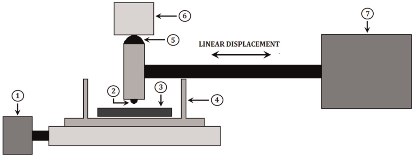
Simplified schematic diagram of high-frequency friction machine (1: friction force transducer; 2: ball; 3: disk; 4: heater block; 5: roller; 6: normal load; and 7: oscillator driver).
Then, test parameters such as load, frequency, and stroke were selected and introduced into the computer. The maximum contact pressure was selected in such a way that wear would be produced with a low number of cycles. A program collects the data generated, which was basically the friction coefficient versus time. The tests were carried out up to 36,000 cycles. This was predetermined with several preliminary tests, to know how many cycles were necessary to cause damage on the surfaces. Finally, three experiments were carried out for each test type. Table 2 shows the operating conditions of the tests conducted.
Test operating conditions.

Results and discussion
Microhardness and roughness
The microhardness of the boride surfaces was measured at five different locations by means of a Vickers indenter with a load of 50 g. The roughness values were measured using a Mitutoyo Surftest Profilometer. Figure 5 shows the hardness depth profile of the borided steels, and Table 3 shows the average values of microhardness and roughness.
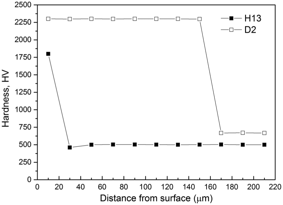
Hardness depth profile of borided steels.
Properties of the boride steel substrates.

SEM observations and EDS analysis
The cross-sectional view of SEM micrographs obtained on the borided AISI H13 and D2 steels at 1273 K for 8 h is shown in Figures 6 and 7, respectively. For the AISI H13 steel, boride layer is grown on the substrate with a saw-toothed morphology (Figure 6(a)). The needles of

(a) SEM micrographs of the cross sections of the borided AISI H13 steel at 1273 K for 8 h, (b) EDS spectrum of borided sample at surface, and (c) EDS at interface.

(a) SEM image of microstructure of the AISI D2 boride layer obtained at 1273 K with an exposure time of 8 h and (b, c) EDS spectrum of borided sample.
Chromium can modify the structure and the properties of boride layer. The solubility of chromium in the Fe2B phase causes the replacement from iron to chromium and forms (Fe, Cr) B and (Fe, Cr) 2B on the surface. The diffusion leads to the decreasing of thickness of boride layer and the increasing of the smooth boride layer/substrate interface. 24 Chromium also promotes the formation of boron-rich phase, such as FeB phase, onto the boride layer.
For example, in boronized stainless steel, alloying elements cause the thin smooth interface of almost 100% FeB phase of the boride layer.
For both steels, the results show that the chromium dissolves in the
XRD analysis
The growth of boride layers is a controlled diffusion process with a highly anisotropic nature. In the case of
The results of XRD studies presented in Figure 8(a) and (b) show the XRD pattern recorded on the surface of borided AISI H13 and D2 steels, respectively. They confirm that iron boride (FeB), iron diboride (Fe2B), and chromium boride (CrB) phases on AISI H13 and iron diboride (Fe2B) and chromium boride (CrB) phases on AISI D2 were all formed during the process at a temperature of 1273 K for a treatment time of 8 h. As an alloying element, Cr was present at about 5 wt% in H13 steel and 12 wt% in D2 steel; apparently, during powder-pack boriding, it also reacted with boron atoms and formed CrB. The diffraction peaks relative to the FeB and Fe2B phases are easily identified. We could only observe peaks for FeB, confirming that the external surface of the boride layer is mostly made of this phase on AISI H13 steel and peaks for Fe2B on AISI D2 steel. However, in the regular XRD spectrum, CrB phase was also detected. For the AISI H13 and D2 steels, crystals of the Fe2B type orientate themselves with the z-axis perpendicular to the surface. Consequently, the peaks of the Fe2B phase belonging to crystallographic planes, having a deviation from zero of the l index, showed increased intensities in the XRD spectra.
29
In the case of the AISI D2 steel, the diffraction peaks of Fe2B phase exhibited a difference in intensities. The growth of

XRD pattern obtained at the surface of the borided steels: (a) AISI H13 and (b) AISI D2.
Rockwell-C adhesion test
SEM images of the indentation craters for samples borided at 1273 K for 8 h are given in Figure 9. For the AISI H13 steel (Figure 9(a)), the indentation craters obtained on the surface revealed that there were radial cracks at the perimeter of indentation craters. It is probably that the presence of the FeB phase conducted to this behavior. However, a small quantity of spots with flaking of delamination was visible, and the adhesion strength quality of this boride layer fits the HF5 category. In the case of the AISI D2 steel, some small cracks and no visible delamination are observed (Figure 9(b)), and the adhesion strength quality is related to HF3 map. The difference in the adhesion between the two borided steels is mainly due to the content of carbon and chromium (see Table 1). The high content of C and Cr in the D2 steel provides a better diffusion of boron and therefore a good adhesion.

SEM micrograph showing the indentation of VDI adhesion test: (a) AISI H13 and (b) AISI D2.
Tribological characterization
During the tests, the friction coefficient was recorded. Figure 10 shows the average behavior of the friction coefficient of the borided and unborided surfaces under dry sliding conditions against a steel ball. The image shows that the unborided sample exhibits a friction coefficient higher than that of the borided substrates. For H13 borided steel, some fluctuations in the first 4000 cycles were observed, mainly due to the running in period in the contact occurred with the asperities. For other tests, a constant behavior was observed. The average friction coefficient for the borided samples was between 0.15 and 0.25 approximately and for the unborided substrates was between 0.3 (H13 steel) and 0.4 (D2 steel) approximately. These results are in agreement with those obtained in other works. 7

Variation of friction coefficient in borided and unborided substrates.
The tests caused wear scars on the flat specimens (disks). There were measurable grooves on the disks. The wear depth of each groove was measured using a Mitutoyo Surftest Profilometer. Due to the depth varying along the length of the groove, a number of depth measurements (transverse to the length of the groove) were taken. The experimental average depth was taken from these measurements. The volume of a “perfect groove” could be calculated from this information as done in previous studies. 30 The profiles in Figure 11(a) show grooved features, demonstrating the two-body wear mechanism and also indicating that the unborided steel surface was more severely worn compared to the borided surface. The form of profiles for D2 and H13 borided steels was mainly caused by their microhardness and adherence properties (Figures 5 and 9, respectively). Furthermore, the measured wear volumes for the unborided and borided surfaces on test steels show a remarkable difference, as apparent in Figure 11(b). This difference is due to the unborided surface having less resistance to sliding wear, mainly due to the lower microhardness.

(a) Profilometry of unborided and borided H13 and D2 steels and (b) specific wear volume.
Table 4 shows a comparison between the specific wear rates of the borided H13 and D2 steels and those reported in other works.2,31–34
Comparison of specific wear rates.

Figure 12(a) and (b) shows the SEM images of the AISI H13 borided surfaces obtained at 1273°K with an exposure time of 8 h. It shows the wear condition characterized by the presence of zones of partial failure and zones with a complete degradation of the boride layer. Figure 12(c) shows the SEM image of unborided surface wear scar produced during sliding contact against a steel ball. Some pits and spalls as well as cracks are observed. It is clear that a great damage formed on this unborided surface.

SEM images of wear scar on surfaces of AISI H13 steel: (a, b) borided surface at 1273 K with an exposure time of 8 h and (c) unborided surface.
Figure 13(a) and (b) shows the SEM images of the AISI D2 borided surfaces obtained at 1273 K with an exposure time of 8 h, and Figure 13(c) and (d) shows the SEM images of unborided surface wear scars produced during sliding contact against a steel ball. In Figure 13(a) and (b), a defined wear scar is produced, which has a width of approximately 0.57 mm. Some pits and spalls are observed and common wear mechanisms like plastic deformation, cracks, and scratching were formed on the borided surface. Figure 13(c) and (d) shows the wear scar formed on the unborided surface, which has a width of approximately 1.45 mm. Likewise, some pits and spalls are observed and cracks and scratching were formed but with a higher degree of wear.
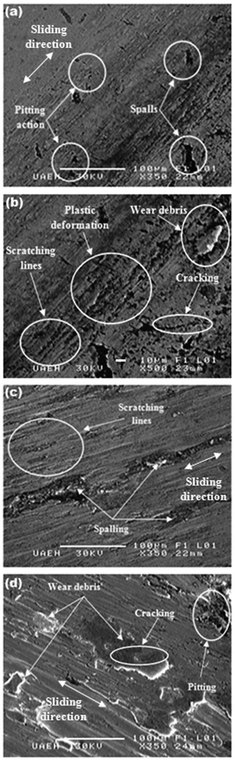
SEM micrographs of wear scar on surfaces of AISI D2 steels: (a, b) borided surface at 1273 K with an exposure time of 8 h and (c, d) unborided surface.
Conclusion
In this work, AISI H13 and D2 steels were pack-borided at a temperature of 1273 K using an exposure time of 8 h. The concluding points derived from this work are as follows:
The FeB, Fe2B, and CrB layers were formed on AISI H13 and D2 steels. This result was confirmed by XRD analysis.
The interfacial adherence of the boride layer on AISI H13 and D2 steels, by the Daimler-Benz Rockwell-C indentation technique, was found to be related to HF5 and HF3 categories, respectively.
Sliding wear resistance for the borided steels was 13 times greater than that of the unborided surfaces.
The unborided steels exhibited a friction coefficient higher than that of the borided substrates.
The characteristic wear mechanism for the H13 borided surface was plastic sliding wear, and for H13 unborided substrate, cracking and spalling were observed.
The characteristic wear mechanism for the D2 borided surface was plastic deformation, cracking, and abrasion.
Footnotes
Acknowledgements
The authors acknowledge Dr JR Laguna Camacho, of the Universidad Veracruzana, for the valuable contributions in the revision of this paper.
Academic Editor: Ramiro Martins
Declaration of conflicting interests
The author(s) declared no potential conflicts of interest with respect to the research, authorship, and/or publication of this article.
Funding
The author(s) received no financial support for the research, authorship, and/or publication of this article.