
Abstract
To ensure the perpendicularity of drilling holes in aircraft manufacturing, the attitude of spindle axis must be adjusted to coincide with the normal vector of drilling point before drilling. The double eccentric discs-spherical pair structure was used as attitude adjustment mechanism in drilling end-effector. Therefore, the attitude adjustment algorithm of spindle axis is proposed in this article. There were two attitudes for current and target position, respectively, and the rotation sequence of each eccentric disc would affect the attitude adjustment efficiency. This article presents the path planning and optimal solution choosing from multiple solutions. Finally, the effectiveness and accuracy of the algorithm are verified in simulation and drilling experiment, resulting in a normality tolerance of ±0.5° and precision of H9.
Introduction
The automotive industry extensively uses robots to efficiently manufacture automobiles with high quality and low defect rates. 1 With the increasing demand for aircrafts, it is essential to apply the robot technology to the aerospace industry. The robot drilling system has been widely applied in the aviation industry. 2 However, the strength of joints greatly affects the service life of aircrafts. It is reported that 70% fatigue failure of airplane body is due to joint problems and 80% fatigue crack occurs in the connecting holes.3,4
One of the important indicators to evaluate the quality of holes is perpendicular precision. Low perpendicular precision of drilling holes will make stress concentration and fatigue crack, resulting in poor hole quality.5,6 So, it is necessary to adjust attitude of spindle axis before drilling holes. At present, only a few companies, such as Electroimpact, Boeing, Airbus and Fatronic Tecnalia company, have matured application of attitude adjustment in robot drilling system.7 –10
Electroimpact added two rotational axes to provide the capability to normalize the spindle axis relative to the workpiece surface. The pivot points for these axes were offset from the workpiece surface. 11 The second generation of Electroimpact’s ONCE (ONe-sided Cell End effector) robotic drilling system used three unique nose pieces to realize auto-normalization. The robot was controlled closed loop around the sensors to normalize the end-effector when deviation beyond a specified threshold from normal exists. 12 But this article does not tell the principle in detail and cannot obtain the key technology.
YC Shan et al. 13 designed a 2R1T three parallel mechanism to adjust the spindle axis. An attitude adjustment mechanism with 2 degrees of freedom of rotary motion was designed by L Zhang and X Wang,14,15 and the 2 degrees of freedom were perpendicular to each other. It can adjust the spindle axis parallel to the normal of drilling point. R Zhang et al. 16 also proposed a method to adjust spindle axis with 2 degrees of freedom. However, all the parallel mechanisms for attitude adjusting are confronted with a same problem. The drill point needs to be removed again after adjusting the drill attitude.
In our drilling system, the end-effector is mounted on KUKA industrial robot. Double eccentric discs normal adjustment mechanism is designed to adjust attitude. 17 In order to ensure the perpendicularity of holes in aircraft manufacturing, the attitude of spindle axis must be adjusted to coincide with the normal vector of drilling point before drilling. The centre of spherical bearing pair is the centre of pressure head, so the drill point remains the same after adjusting attitude and the drill axis avoids repeating adjustment. And improving the drilling efficiency is critical for aircraft manufacturing. Therefore, how to accurately and efficiently send spindle to target position is a research emphasis in our automatic drilling system.
C Wang and P Yuan 5 proposed the movement planning and algorithm simulation of attitude adjustment. In order to be more energy-efficient, this article aims at the path planning and optimal solution choosing from multiple solutions to send spindle to target position quickly and accurately. The effectiveness of the path planning is verified through simulation. Finally, the verification experiment of attitude adjustment and drilling experiments certifies the accuracy of algorithm.
The attitude adjustment algorithm
In the drilling process, the spindle attitude must be adjusted when spindle axis deviates from the normal vector of the drilling point more than

Schematic diagram of double eccentric discs mechanism.
The geometric centreline of macro-eccentric disc is line O. Line
The spherical plain bearing is embedded in micro-eccentric disc, and the micro-eccentric disc is embedded in macro one. With respective rotation of the two eccentric discs, the tail shaft swings discretionarily in spherical plain bearing to drive spatial attitude adjustment of the spindle axis.
The drill vertex coincides with the spherical centre

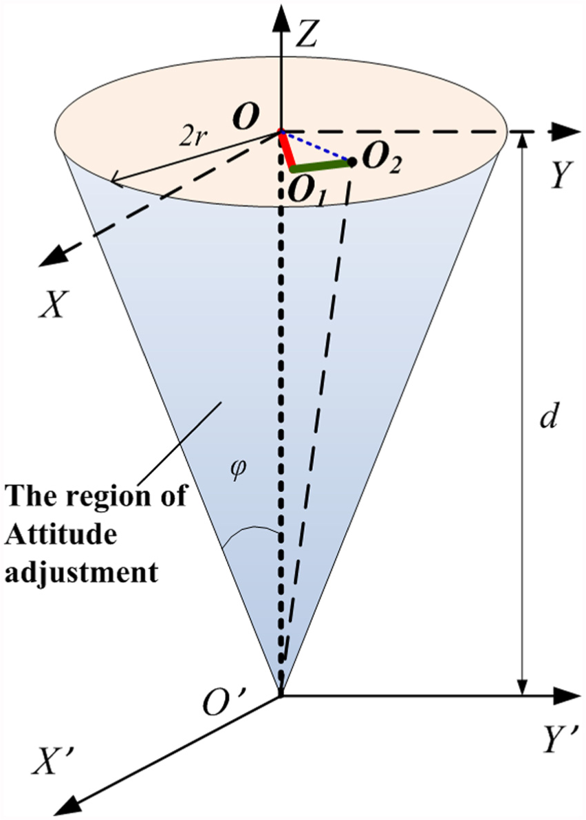
Region of attitude adjustment.
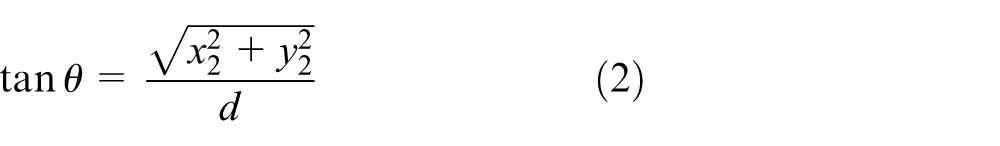
where
The essence of attitude adjustment is making the spindle axis coincide with the normal vector of the drilling point. First, the normal vector is obtained to calculate the angle between spindle axis and vertical direction. If the angle is more than
Double eccentric discs mechanism can be simplified as two-link model, as shown in Figure 3. The length of rods is eccentricity

Two-link model.
The double eccentric discs coordinate system is
When
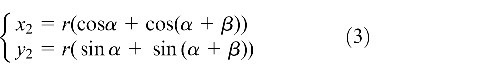
For current position

Coordinate system of double eccentric discs plane.
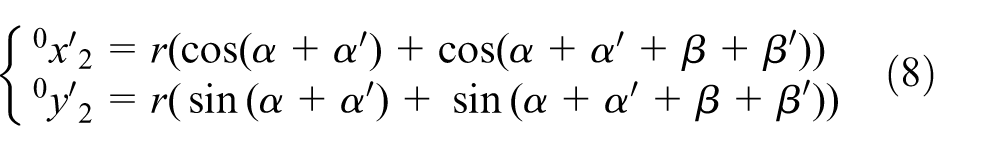
The target position is
Suppose

where
In

If

where
For every

where
According to geometric position, the target position
When the spindle axis needs to adjust attitude again, the system will regard the current attitude as the former attitude and repeats to calculate the above equations to get new rotary angles. Then, two motors control two eccentric discs to make the spindle axis coincide with the target attitude.
Path planning
Both the macro- and micro-eccentric discs are driven by high-precision DC servo motors through gears. Double eccentric discs rotate different angles and make spindle axis coincide with normal vector. According to measure unit, robot system can transform it to the corresponding angle
The current attitude of spindle is not always the origin position. It returns to the initial position and then begins to adjust every time, which will greatly reduce the efficiency. In order to be efficient and energy saving, it is necessary to adjust spindle attitude with the shortest path. The drilling system needs continuous attitude adjustment in actual adjustment process. The algorithm of attitude adjustment regards the current attitude as the start of next attitude. So, the path planning is how to adjust the spindle from current position to target position quickly.
There are two attitudes of macro- and micro-eccentric disc in current position. Similarly, in target position, there are two attitudes of spherical plain bearing centre moving to the target point. So, four solutions can be obtained after combination. However, there are two directions (clockwise and counterclockwise) that macro-eccentric disc can rotate, so the mechanism can move from


How to plan the rotational paths of macro- and micro-eccentric disc? And how to find out the optimal solution to target position from eight solutions and move the spindle axis to normal vector with high efficiency? The problem is how to choose the optimal solutions of

Two attitudes in same point.
In order to reduce time,
The motion simulation of double eccentric discs was done in Adams according to the attitude adjustment algorithm. From origin position to target position, the mechanism of double eccentric discs is simplified to reduce calculation, which is shown in Figure 6. The green solid line is the trajectory of spherical plain bearing. The red eccentric disc is macro and yellow is micro.

Motion simulation in Adams.
There are four ways to adjust attitude according to rotary speed of motor and rotational order of macro- and micro-eccentric disc. Four groups of trajectory are obtained by simulations in Adams, as shown in Figure 7.

Four groups of simulations.
Keep the macro-eccentric disc immobile, and micro-eccentric disc rotates
Keep the micro-eccentric disc immobile, and macro-eccentric disc rotates
Macro- and micro-eccentric discs rotate
Macro- and micro-eccentric discs rotate
Export the data of four groups of trajectory and draw curves in MATLAB, as shown in Figure 8. The blue dotted line is the trajectory of centre

Four groups of trajectory.
According to the trajectory and the length of the curve, the red solid line is repeated by rotating eccentric discs separately as shown in Figure 7(1) and (2). Obviously, it is not desirable to improve the efficiency of the system. In Figure 7(3) and (4), the two eccentric discs rotate together and the fourth curve is shorter and smoother than the third one. So, the fourth group of trajectory is more stable and shorter path in comparison with four different trajectories. So, we choose the fourth group as the best path.
The verification experiment of attitude adjustment
Before drilling experiments, the attitude of spindle axis should be adjusted to coincide with normal vector by the rotation of motors. In order to ensure perpendicularity of holes, this article designs verification experiments of attitude adjustment.
First, adjust the plane of pressure head at random, and three laser sensors measure the distance to the plane. The normal vector of drilling point can be calculated based on the principle of non-collinear three points define a plane, as shown in Figure 9.

Normal vector measured by laser sensors.
In Figure 9,
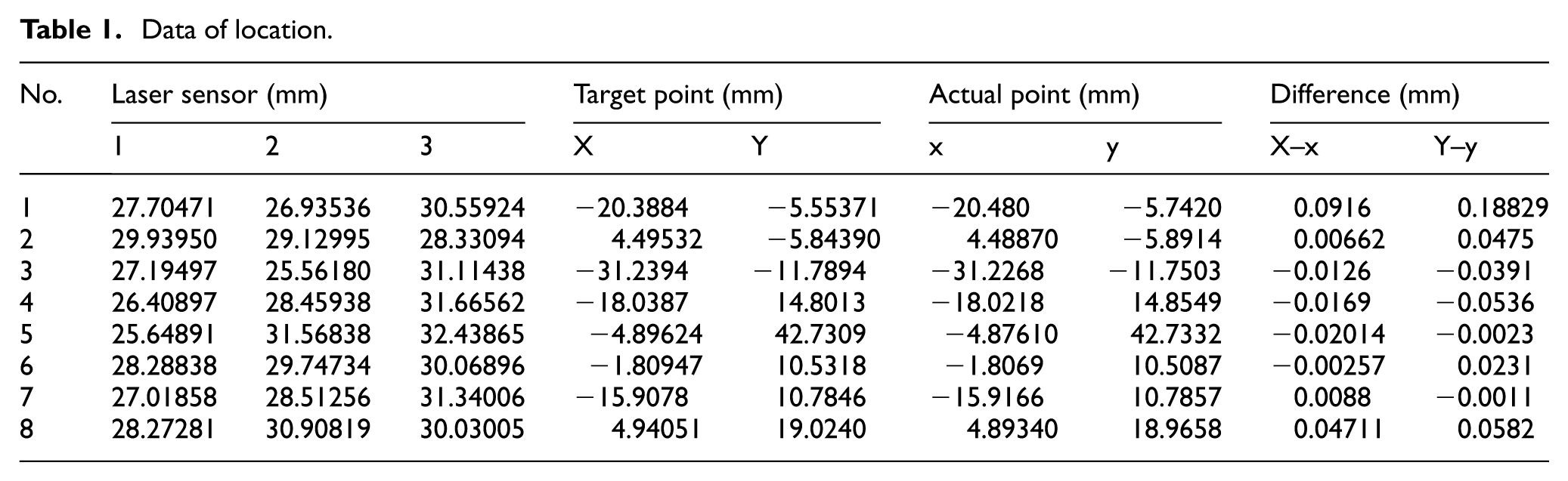
From a large number of trials, eight experiments are selected, and the target point, actual position, the value of laser sensor and rotational angles are recorded in each experiment. Then, the theoretical angle, the actual angle between spindle axis and origin axis, is calculated by equation (2), as shown in Tables 1 and 2.
Data of location.
Data of angle.

The theoretical rotational angle of macro-eccentric disc is
As shown in Table 2, the angle between theoretical normal vector and actual attitude of spindle axis is
The drilling experiments
The feasibility and correctness of the algorithm of attitude adjustment have been verified in simulation and verification experiment. This article also designs the drilling experiments to test the quality of holes. The carbide drill is used in drilling experiments because it performed well during the drill. 18 The material of test specimen (thickness = 6 mm, flat plate) is aluminium alloy 2024, and the drill diameter is 6 mm. Experimental conditions include spindle speed of 500 r/min, feed 0.1 mm/s and pressure 0.3 MPa. In order to test the influence of attitude adjustment on actual drilling, there are two groups of drilling experiments, no attitude adjustment and attitude adjustment. The drilling experiments were carried out, and the effect of the hole is shown in Figure 10.

Effect of drilling: (a) with no attitude adjustment and (b) with attitude adjustment.
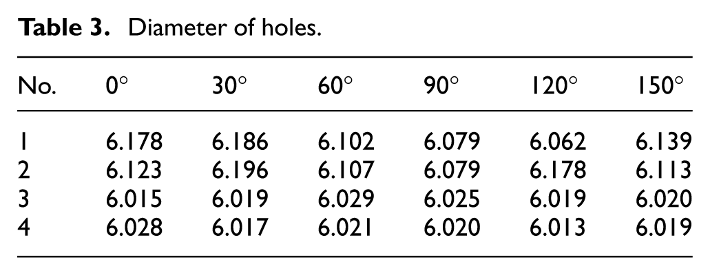
The inside micrometer was used to measure the diameter of four holes along the circumferential direction every
Diameter of holes.

Tolerance of drilling holes.
Results
Holes 1 and 2 are the holes with no attitude adjustment and holes 3 and 4 with attitude adjustment. In Figure 10, the shape of holes 1 and 2 is oval and more burr. The main reason is that the angle between normal vector and spindle axis is too large without attitude adjustment before drilling. So, the drill is tilted, causing oval holes. At the same time, the surface of aluminium alloy has a lot of burr.
The tolerance of four holes’ diameter is shown in Figure 11. The fluctuation of holes 1 and 2 is large without attitude adjustment of spindle axis. However, the data of holes 3 and 4 are stable, and the hole is circular.
As shown in Table 3, the tolerance of hole 1 is 124 µm and hole 2 is 117 µm. With the attitude adjustment of spindle axis, the tolerance of holes 3 and 4 is 29 and 28 µm, respectively. The accuracy of holes satisfies the requirement and reaches H9. (According to the national standard of mechanical design, H9 refers to the tolerance grade 9, and the tolerance zone of hole is 30 µm for diameter 6 mm.)
Conclusion
In order to ensure the perpendicularity of drilling holes, spindle axis must be adjusted to coincide with the normal vector of drilling point automatically and efficiently before drilling. The double eccentric discs-spherical pair structure was used as attitude adjustment mechanism in drilling end-effector. So, the attitude adjustment algorithm of spindle axis was based on this mechanism.
The uncertain attitudes of current and target positions, and the rotation sequence of each eccentric disc, would affect the attitude adjustment efficiency. In summary, there were eight solutions in total. This article presented the path planning and optimal solution choosing from multiple solutions. Finally, the effectiveness and accuracy of the algorithm were verified in simulation and drilling experiment.
From the results of simulation and experiments, the conclusions are as follows:
The minimum sum of rotational angles of macro- and micro-eccentric disc is the optimal solution.
The best path is that macro- and micro-eccentric discs rotate
The angle between normal vector and actual direction of spindle axis meets the tolerance of ±0.5°.
The precision of holes satisfies the tolerance requirement and reaches H9.
Footnotes
Academic Editor: Zhijun Li
Declaration of conflicting interests
The author(s) declared no potential conflicts of interest with respect to the research, authorship and/or publication of this article.
Funding
The author(s) disclosed receipt of the following financial support for the research, authorship and/or publication of this article: This study was supported by the National Natural Science Foundation of China (no. 61375085).