
Abstract
This article describes an analytical model of the cantilever-type energy harvester based on Euler–Bernoulli’s beam theory. Starting from the Hamiltonian form of total energy equation, the bending mode shapes and electromechanical dynamic equations are derived. By solving the constitutive electromechanical dynamic equation, the frequency transfer function of output voltage and power can be obtained. Through a case study of a unimorph piezoelectric energy harvester, this analytical modeling method has been validated by the finite element method.
Introduction
With the rapid advancement of information technology in the past 20 years, we are facing a new era of Internet of things (IOTs). However, this new technology is greatly dependent on various kinds of wireless sensor nodes (WSNs), 1 portable electronics, 2 and micro-electromechanical system (MEMS) devices. 3 Currently, most of them are powered only by batteries, which may limit the whole system’s operational time and performance by periodically replacing or recharging these batteries. Since MEMS are scaled down in the range of 100 nm–1 mm and WSNs operate cyclically, the required power for one separate device is limited into micro-Watt level, which makes it possible to develop regenerative micro power supply such as solar cells, thermoelectric energy harvester, and mechanical vibration energy harvester 4 to power these devices. However, compared with conventional battery technology, all of these complementary schemes have their corresponding advantages and disadvantages. Cook-Chennault et al. 5 had ever reviewed these power solutions for portable MEMS devices, where the author made an emphasis on piezoelectric vibration generator for its structure simplicity, easy fabrication, high output voltage, and long lifespan duration. In this article, we mainly focus on the analytical modeling of piezoelectric vibration energy harvester.
The typical structure of piezoelectric scavenger is the rectangular cantilever beam, 6 which mainly consists of an elastic substrate and a piezoelectric layer as shown in Figure 1, where one end of the beam is fixed with host structure and the other end is kept free. When the host structure is vertically vibrating, the fixed end will rigidly translate along with the fixture, and the free end will move with a lagged phase, by which mechanical strains are induced in the dynamic vibrating process. If the piezoelectric patch is coated with electrodes on top and bottom surfaces, electric charges across the electrode surfaces on the basis of direct piezoelectric effect can be induced from the mechanical strain.

Schematic figure showing the dynamic motion of the unimorph piezoelectric energy harvester.
In this article, the structure is outlined as follows. In section “Analytical model of piezoelectric unimorph cantilever energy harvester,” the analytical model of piezoelectric unimorph cantilever energy harvester is described. Section “Multimode frequency response of the unimorph cantilever beam” provides multimode frequency response of the unimorph cantilever beam. In section “Case study of piezoelectric unimorph cantilever scavenger in bending mode,” both analytical and numerical results are compared to prove the validity of the analytical method. Beside this, the transient dynamic response of the device is also characterized. The conclusion remarks are finally made in section “Conclusion.”
Analytical model of piezoelectric unimorph cantilever energy harvester
When the composite cantilever beam vibrates with host structure vertically, arbitrary point P will translate from the original position to terminal position

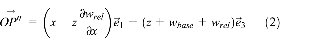
In order to characterize the dynamic motion with respect to reference coordinate, the absolute velocity of point

And the relative displacement of

Based on the continuum thermodynamics, the strain tensor can be denoted as

where

As the linear electrical enthalpy of piezoelectric material can be approximated by7,8

Then, the constitutive relation derived from equation (7) can be obtained as


In equations (7)–(9), the terms
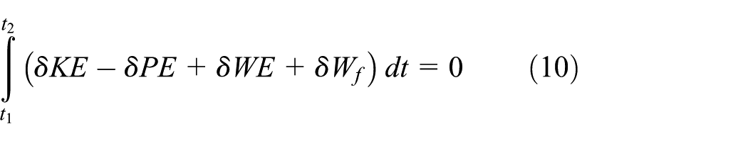
where KE, PE, WE, and


where
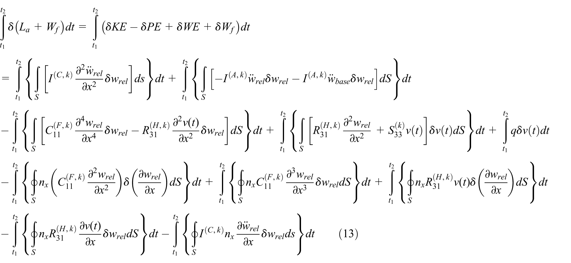
where


In the equations,


where

The solution to the ordinary differential equation (19) is obtained as

where


The associated boundary conditions are given as

Combining equations (20) and (21), the coefficients

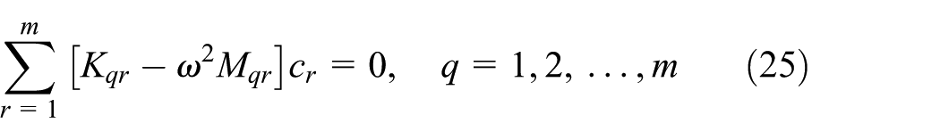
In order to obtain a nontrivial value of

where

Multimode frequency response of the unimorph cantilever beam
If Ritz method is utilized to represent the transverse displacement, the solution form can be expressed as

where
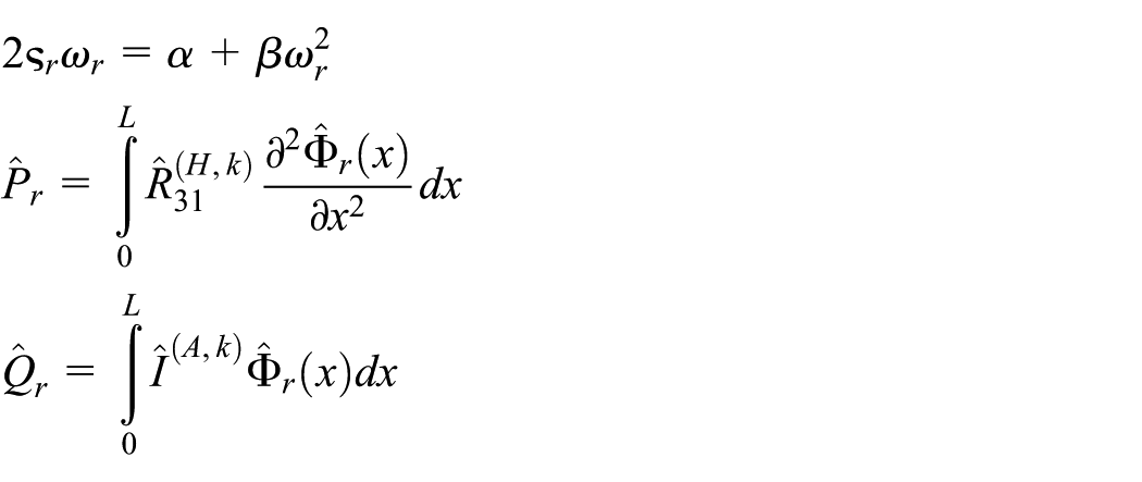
As the values of

If

Then, equation (24) can be rearranged as

By substituting equation (28) into equations (17) and (18), the dynamic equations can be rewritten as

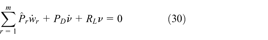
where
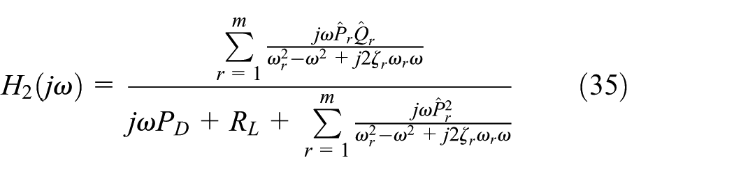
If Laplace transforms are applied into equations (29) and (30), the transfer functions of

The time-dependent dynamical responses of voltage and power outputs are deduced as equations (33) and (34), respectively


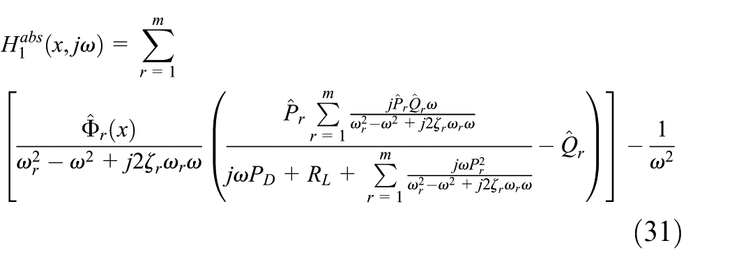
Correspondingly, the frequency response functions (FRFs) of

From equation (34), the optimal harvested power will be determined by setting the external load resistance
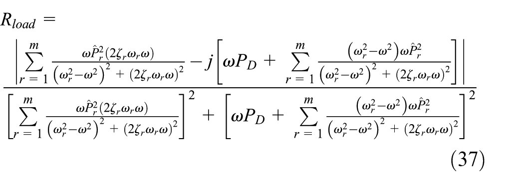
The optimal resistance is obtained by differentiating equation (36) with respect to
Case study of piezoelectric unimorph cantilever scavenger in bending mode
Analytical simulation
In order to prove the feasibility of the model, the basic unimorph cantilever structure for the vibration energy harvesting device is proposed. Piezoelectric material of PZT-5H10,11 is used in the top layer where the polarized direction is set upward in the vertical direction. Parameters for PZT-5H including stiffness constant
Dimensions of geometric structure and corresponding coefficients.

Since the order of

Through the numerical calculations, the first three resonant frequencies are determined to be 162.0125, 1015.3149, and 2842.9110 Hz, respectively. The first three bending mode shapes can be obtained and they are plotted as shown in Figure 2.

Bending mode shapes of the cantilever beam at 162.0125, 1015.3149, and 2842.9110 Hz.
By further substitution of these parameters and normalized mode shapes into equation (35), the FRF of output voltage is determined. From the results shown in Figure 3(a), the highest output voltages around the first three modes are 0.526 V/g, 0.00437 V/g, and 0.1944 mV/g in open circuit. With the load resistance being decreased, the output voltage monotonically diminishes and finally reaches a minimum value of 0.00471 V/g at 100 Ω. However, when it comes to power output response, the maximum power output at 162 Hz is 13.6 µW/g2, where the impedance of the piezoelectric energy harvester is matched with a resistance of 11.043 kΩ. Similarly, the output power generated across the load resistances at 100 Ω, 679 Ω, 1.9 kΩ, and 30 kΩ all present peak values at 160 Hz, while for peak value of output power at 10 MΩ, the corresponding frequency is shifted to 162.5 Hz. This frequency shift is due to the fact that the response functions of voltage and power are related to load resistance and piezoelectric power; the frequency of the peak value of output power is shifted according to formulas (35) and (36). For second mode at 1015 Hz, the maximum power output is 5.13 nW/g2, where the optimum load resistance of 1.9 kΩ is proved. The resonant frequencies for devices with load resistances of 100 Ω, 679 Ω, and 1.9 kΩ are 1015 Hz, while for that of 11.043 kΩ, 30 kΩ, and 10 MΩ, the frequencies are shifted to be 1014.5 Hz. In the third mode, the maximum power output is 27.614 pW/g2 at the load resistance of 679 Ω. The resonant frequencies for the load resistance of 100 Ω, 679 Ω, and 1.9 kΩ are 2824, 2817.5, and 2811.5 Hz, respectively. The third resonant frequencies in other cases are all 2810 Hz. The effective factors to the resonant frequency include the geometric dimensions, Young’s modulus, stiffness, and mass densities, which can be found from the combination of formula (38), expression for µ, and

Frequency response functions (FRFs) of (a) output voltage and (b) power.
Numerical analysis
In this section, we use the finite element analysis package ANSYS 12.0 to validate the proposed analytical method. Although the geometric structure dimensions are still the same as described in section “Multimode frequency response of the unimorph cantilever beam,” there are some differences on material constants that need to be clarified. Finite element method (FEM) has been widely used in modeling mechanical energy harvesting devices.
12
In the analytical method, as the beam model is simplified to Euler–Bernoulli type and only transverse displacement is considered, beam width plays no effect on the whole device output performance. Therefore, the geometric model can be built in a two-dimensional domain in ANSYS software. Here, plane elements plane223 and plane82 are used for modeling the piezoelectric and substrate layers. Since plane223 is used in a piezoelectric-coupled field analysis, it works either in a plane stress or plane strain condition, where more material constants such as
Material parameters for PZT-5H.

In the modal analysis, the composite beams are modeled by two glued rectangles where one end is fixed and the other end is kept free. On the top and bottom surfaces of piezoelectric layer, the electrodes are modeled using the coupled commands. The mode shapes of the geometric structure in displacement contour are shown in Figure 4. The mode shape of the rectangular cantilever beam in FEM is the same as that in analytical simulation, which can be proved by the calculated resonant frequencies and the shapes. Although the shapes at mode 2 between analytical and FEM methods are in opposite directions, they are attributed to the negative value of coefficient

Mode shapes of the rectangular cantilever beam in FEM.
As the first three mode shapes and resonant frequencies are determined, the dynamic response of output voltage and power should be characterized as well. In analytical method, the optimum resistance around the first three resonant modes is determined to be 11.043 kΩ, 1.9 kΩ, and 679 Ω according to equation (37). In FEM, we calculate the optimum external load resistance according to

where

Frequency response functions (FRFs) of (a) output voltage and (b) power in FEM.
The maximum power output at 162 Hz is 35.4697 µW/g2, where the optimum resistance of 10.06 kΩ is matched to the piezoelectric energy harvester. The generated peak output power at 162 Hz across 100 Ω, 574.565 Ω, 1.607 kΩ, 30 kΩ, and 10 MΩ are 0.98979, 5.49292, 14.0783, 22.6027, and 0.008787 µW/g2, respectively. For the second mode at 1015 Hz, the maximum power output is 743.688 nW/g2, where the optimum resistance is changed to be 1.607 kΩ. Correspondingly, the induced power across 100 Ω, 574.565 Ω, 10.06 kΩ, 30 kΩ, and 10 MΩ are 93.7168, 474.044, 236.42, 81.4825, and 0.24578 nW/g2, respectively. In the third mode, the peak output power is 31.0336 nW/g2 at 2836 Hz, where the matched external load resistance is 574.565 Ω. Similar to previous analytical results, the resonant frequencies across 100 Ω, 1.607 kΩ, 10.06 kΩ, 30 kΩ, and 10 MΩ are shifted to be 2843, 2831, 2830, 2829, and 2829 Hz, respectively. Through the comparison of the results between analytical method and FEM, the power output around the first resonant mode is comparable with each other, while the difference in the outputs at second and third modes is quite large. The reason to this result is attributed to the assumption of plane strain in FEM. In FEM, not only


Comparing the modified constitutive equations with formulas (11) and (12), the terms
Transient analysis of the dynamic response
In the transient analysis using FEM, we focus on the dynamic response at the first mode, where the external driving frequency is set constant at 162.26 Hz. The vibration displacement amplitude at the fixed end is set with a value of 3.96 µm, which means that the acceleration amplitude is defined to be 0.104 m/s2 (approximately 0.01 g). External load resistor of 10.06 kΩ is connected to the piezoelectric layer. When the device is working, the fixed end of the cantilever vibrates rigidly with the external excitation. But for the free end, it will induce relative transverse displacement with respect to the rigid moving base because of the transverse bending motion. Through the finite element analysis, the displacement response of the tip is shown in Figure 6(a) and (b). From the sinusoidal wave, it is found that the displacement oscillates cyclically around the equilibrium point with a time period of 6.16 ms. Initially, the tip motion is in a transient status in 0.72152 s. After it transcends this time period, the oscillation is kept stable at amplitude of 0.543 mm, which can be observed in the zoomed out Figure 6(b).

(a) Transient dynamic response of tip displacement in 2 s and (b) zoomed out figure of transient dynamic response of the tip displacement at stable state.
The transient dynamic response of the output voltage across the load resistor is shown in Figure 7(a) and (b), where the output voltage response enters a stable state from 0.72383 s. The amplitude of the output voltage is 0.9669 V with a frequency of 162.26 Hz. However, when it comes to the generated instantaneous power across 10.06 kΩ, the frequency is double of 162.26 Hz, as the instantaneous power is calculated by
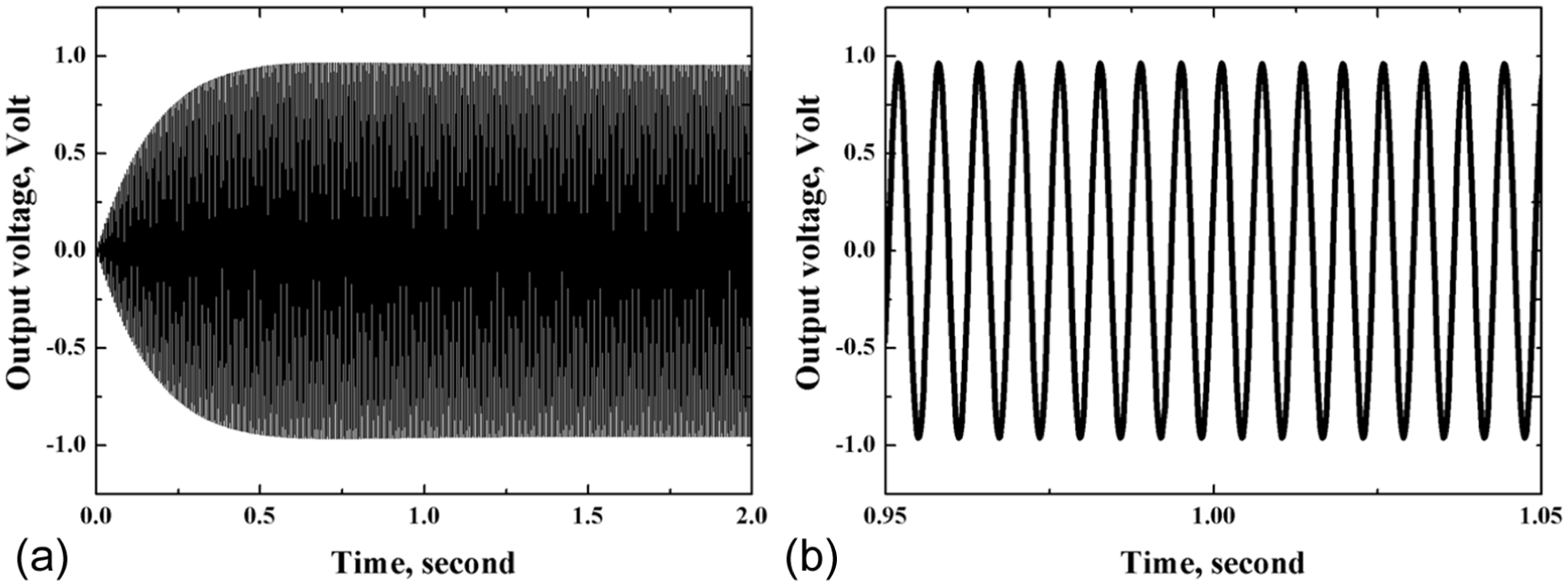
(a) Transient dynamic response of output voltage in 2 s and (b) zoomed out figure of transient dynamic response of the output voltage at stable state.

(a) Transient dynamic response of output power in 2 s and (b) zoomed out figure of transient dynamic response of the output power at stable state.

Open voltage and dissipated electrical energy versus base excitation.
Conclusion
In this article, the analytical model of piezoelectric unimorph cantilever energy harvester has been provided based on Euler–Bernoulli’s beam theory. By expressing the Hamiltonian form of the total energy equation into strong form and weak form, the mode shape functions and electromechanical dynamic equations have been obtained. Utilizing the Ritz method and Laplace transforms, the FRFs of output voltage and generated power across load resistor are provided. To prove the validity of analytical model, a specific unimorph piezoelectric energy harvester has been studied. By substituting the related parameters in the derived formulations, bending mode shapes as well as first three resonant frequencies of 162, 1015, and 2842 Hz are obtained. In order to characterize the dynamic behavior of the device, the varying trends of output voltage and generated power versus driven frequencies are predicted. In this way, the optimum load resistances at corresponding resonant modes are determined. For confirming the effectiveness of analytical model, the proposed piezoelectric energy harvester is also simulated in commercial finite element software ANSYS. Through the specified definition of the material property and modeling elements, the calculated first three bending mode resonant frequencies—162, 1015, and 2841 Hz—coincide well with analytical results. Through the static analysis of piezoelectric energy harvester, the resistance of the optimum power output corresponding to each mode is found to be comparable with analytical results as well. By conducting the harmonic analysis, the varying trends of FRFs of output voltage and generated power also agree well with each other. Only one issue that should be noted is that the output values at second and third modes are overestimated compared with the analytical model. This phenomenon is attributed to the fact that the additional coefficients
Footnotes
Academic Editor: Xiaotun Qiu
Declaration of conflicting interests
The author(s) declared no potential conflicts of interest with respect to the research, authorship, and/or publication of this article.
Funding
The author(s) disclosed receipt of the following financial support for the research, authorship, and/or publication of this article: This work was supported by the Natural Science Foundation of Hubei Province (2014CFB835).