
Abstract
It is a necessary mean to realize the accurate motion control of the manipulator which uses end-effector pose correction method and compensation method. In this article, first, we established the kinematic model and error model of the modular manipulator (WUST-ARM), and then we discussed the measurement methods and precision of the inertial measurement unit sensor. The inertial measurement unit sensor is mounted on the end-effector of modular manipulator, to get the real-time pose of the end-effector. At last, a new inertial measurement unit–based iterative pose compensation algorithm is proposed. By applying this algorithm in the pose compensation experiment of modular manipulator which is composed of low-cost rotation joints, the results show that the inertial measurement unit can obtain a higher precision when in static state; it will accurately feedback to the control system with an accurate error compensation angle after a brief delay when the end-effector moves to the target point, and after compensation, the precision errors of roll angle, pitch angle, and yaw angle are reached at 0.05°, 0.01°, and 0.27° respectively. It proves that this low-cost method provides a new solution to improve the end-effector pose of low-cost modular manipulator.
Introduction
It is a new research trend in robotics field, which uses modular technology to develop industrial lightweight manipulator to achieve good performance of precision and low cost. 1 The modular manipulator is composed of joint modules, link modules, end-effector module, and the corresponding drive, control, and communication modules. 2 Among them, the modular joint is a core component of the modular manipulator. It is a highly integrated system module, which integrates a set of mechanical parts, driving parts, sensors, control board, and power supply board, with standard electrical and mechanical interface. Generally, the basic components of modular joint are composed of motor, reducer, feedback elements (photoelectric encoder, rotary encoder, etc.), and other accessories such as brake, limit switches, sensors, and so on. 3 Among them, the most expensive part is the motor, so the selection of the motor has a direct relationship to the cost of modular manipulator; different motors have different prices in the market, and the price of high-precision motor is often several times more expensive than the ordinary motors, some even up to dozens of times. An important way to enhance product competitiveness is to improve the accuracy while reducing the cost, so it is important and significant to research how to make the modular manipulator which installed low-precision motor to realize high-precision pose control.
There exist errors with the actual motion control of modular manipulator. According to the system evaluation technology, the errors can be divided into systematic error and random error. System error is generated in the process of manufacture and assembly because of the mechanical offset; this kind of error can be corrected by the analysis method and setting up the corrected mathematical model. Such as the correction method proposed by He et al., 4 which is a series correction method based on product index criterion product-of-exponentials (POES) formula, and the mathematical model proposed by Liu et al., 5 which is based on genetic algorithm (GA) to correct the end-effector pose of manipulator. Random error arises from the uncertainty of measurement error, as a result of the design of motor body or errors caused by aged motor, or transmission error which is caused by series manipulator joint angle transmission delay. This kind of error can be corrected by introducing a feedback method, such as the use of optical tracking system (OTS) or inertial measurement unit (IMU) to feedback. Feedback method can also solve the system error. Wiles et al. 6 used the Northern Digital Inc. (NDI) Polaris OTSs to achieve the accuracy pose recognition and avoided cumulative error, but OTS still has its unavoidable problems: marked points lost caused by disturbance and obstruction from other objects and uneven error distribution in the workspace due to the distortion of camera’s lens and other configurations of OTS. Chen et al. 7 combined OTS with IMU, to compensate for pose tracking with IMU in the case of OTS mark point lost. The performance of the OTS was improved by data fusion with an IMU using a Kalman filter. During the period of marker-missing, the data from OTS cannot be trusted, the noise covariance of OTS is set to infinity, and system will run under the compensation model so that the Kalman filter takes only the estimated value in the optimization. The experiment result shows that the position root mean square error (RMSE) is less than 0.34 mm. Stegagno et al. 8 used the RGB-D camera, IMU, and tactile sensor to achieve prediction and obstacle avoidance of the quadrotor indoor. The RGB-D sensor is used for collision-safe navigation using a probabilistically updated local obstacle map. In the operator visual feedback, pan-scanning movement is real-time compensated by an IMU-based adaptive filtering algorithm that lets the operator perform the drive experience in an oscillation free frame. It is able to exploit only onboard sensors, thus being independent from any motion capture system. Zhou et al. 9 by using IMU data combined with Kalman filter, to measure and to track human arm’s movement, compared to the measurement data from OTS, the pose error is less than 3°, and there was no marked point lost, which can meet the low-precision requirements when application. In summary, if only using IMU to estimate manipulator end-effector pose, it has the following advantages: (1) the price is cheaper; the price of OTS measurement tools is often several times more expensive than IMU. (2) There is no loss tracking measurement problem caused by marked point lost. IMU is using its own gyroscope, accelerometer, and magnetometer to get data and to calculate the pose information. It has the advantages of high sampling rate and good short distance precision.
Currently, IMU with nine degrees of freedom (DOFs) is widely studied, which consists of three-axis accelerometers, three-axis gyroscopes, and three-axis magnetometer sensors. In theory, a three-axis gyroscope measures and obtains the angular velocity from three axes. After integrating, it can obtain the relative rotation angle from the corresponding axis. But, in fact, due to the existence of the gyro drift and noise, we will get a bigger pose error when integrating directly. So, we need filter to deal with it. The commonly used pose estimation algorithms are Complementary Filter (CF filter, proposed by Mahony), 10 Gradient Descent (proposed by Madgwick), 11 and Extended Kalman Filter (EKF) (proposed by Cavallo). 12 The CF algorithm doing low-pass filter on accelerometer measurement and doing high-pass filter after integrating measurement value of the gyroscope, and then, the pose angle is obtained by accumulating them together. Gradient descent algorithm, by using of magnetic field distortion compensation and using the quaternion representation, calculating data from the accelerometer and magnetometer for analysis and optimize the gradient descent algorithm. And use it as the directional derivative of a quaternion to calculate the measurement error of gyroscope. The EKF algorithm uses the data from magnetometer and accelerometer sensors to compensate for the pose deviation of gyroscope.
If we can accurately obtain the pose of modular manipulator end-effector by using IMU, then calculate the pose error matrix by error model to compensate for the pose error of modular manipulator according to inverse kinematics; it will compensate for the pose error due to low-precision motors. It provides a new solution to improve the end-effector precision of low-cost modular manipulator.
In this article, first, we analyzed the kinematics model and the error model of the modular manipulator WUST-ARM. Traditional D-H method is used to establish coordinate system and calculate the forward problem. About inverse kinematics, by analyzing the structure of modular manipulator, a geometric method mixed with analytical method algorithm is used to solve the inverse kinematics problem; 13 first of all, we use geometric method to determine the angles of first three joints, and then use the analytical method to solve the angle of the last three joints (wrist). About error model, in this article, generalized error methodology 14 is used to calculate the error between the actual pose and the theoretical pose of the manipulator end-effector. And then we analyze three pose estimation fusion algorithms of IMU. By comparing with those methods which named CF algorithm, 10 gradient decrease algorithm, 11 and standard EKF fusion algorithm, 12 finally we take the standard EKF as the sensor fusion algorithm due to its good estimation result. Based on this, in this article, a new IMU-based iterative pose compensation algorithm is proposed based on the accuracy pose measurement of IMU. With the accurate pose measurement of IMU which is rigidly mounted on the end-effector of manipulator, error matrix can be retrieved by error model. Finally, the pose error of end-effector will be compensated and corrected by several times of iterations until the target accuracy is met.
Manipulator kinematics model
The kinematics of manipulator consists of forward kinematics and inverse kinematics. The forward kinematics is to calculate the position and orientation of manipulator end-effector when the rotation angles of the joints are given. In this article, the traditional D-H parameters method is used to formulate the kinematic model of our modular manipulator. The relationship between link i and link i – 1 can be described by homogeneous transformation matrix of four D-H parameters. As shown in equation (1)

Multiplying the homogeneous transformation matrices together, the end-effector position and orientation matrix of manipulator was obtained. As shown in equation (2)

The inverse kinematics is to calculate joints’ rotation angle of the known manipulator end-effector position and orientation information. There are three traditional methods: analytical method, iterative method, and geometric method. For analytical method, it is difficult to get a solution when there are many variables of the joint, and even cannot obtain the inverse solution, and there is a cumulative error. Iterative method is suitable for most of the manipulators, but it needs multiple iterations which take a long time and cannot meet the requirements of real-time robot control. Geometric method gets its solution after geometric analysis and simplifies the structure of the manipulator. It completely meets the requirements of manipulator real-time control with its high accuracy and fast speed; however, it lacks versatility. In this article, we use an algorithm based on geometric method mixed with analytical method to calculate the inverse kinematics of our WUST-ARM. 13 First, we use a geometric method to calculate the first three joint angles in an intuitive and fast way. Then analytical method is used to calculate the next three joint angles. It well combines the advantages of geometrical method and analytical method to achieve a real-time and high accuracy inverse solution.
As can be seen from the model of WUST-ARM which is shown in Figure 1, the manipulator wrist (joints 4, 5, and 6) axis intersects at one point Pw. After making some geometrical analysis, it can be found that the joint 4 does not give translation contributes to point Pw, so does the joint 6. In the process of getting inverse solution, the pose of end-effector


Relationship among
Thus, we got the coordinate of point Pw. The coordinate of the point Pw is fully determined by the rotation angles of joints 1, 2, and 3. So we can divide the inverse problem into two parts including the first three rotation angles solution and the last three rotation angles (wrist) solution.
1. Solution for

We can get

r and s in Figure 2 can be retrieved by equations (6) and (7)


We can analyze the motion of joints 2 and 3 in the plane in which they are established, as shown in Figure 3. Equations (8) to (12) can be obtained


Solution for θ3.
In


Then

or

There are two set solutions of
Solution for


then


Solution for θ2.
2. Solution for

and

where
Then we can get the solutions of θ4, θ5, and θ6 as equations (18) to (20)


Manipulator error model
The error model of the manipulator is the theoretical basis of the error compensation and correction. The error analysis theory which is based on the screw theory; the homogeneous matrix; the D-H coordinates; and the Jacobian matrices have been fully developed and applied at the end of the last century. 14 In addition, some theories focus on the consideration about the effect of the joint errors, and the link errors on the manipulator position and orientation compensation have achieved good results.15–17 In this article, because we want to do the error compensation based on the actual pose information which is measured by IMU from manipulator end-effector, so we established error model by using a generalized error method, 14 and focus on the relationship between actual pose and theory pose of manipulator end-effector.
As analysis in section “Manipulator kinematics model” shows, we know that forward kinematics is going to calculate the position and orientation of the manipulator end-effector

where s is the structural parameter of the modular manipulator, and
In the actual motion control of manipulator, it is unavoidable to have errors. The classification and the causes of the errors as mentioned in the previous section. Because of the existence of errors, there is a certain degree of displacement between actual pose


Relationship between the theoretical pose and the actual pose.
Among them,

IMU pose estimation
In this article, the IMU we used is from LPMS company production. It is a nine-axis IMU which contains three different micro-electromechanical system (MEMS) sensors: accelerometer, gyroscope, and magnetometer. As shown in Figure 6(a), the Z axis is perpendicular to IMU plane upward, and the coordinate systems used is defined as right handed Cartesian coordinate system with X axis and Y axis on the IMU plane. Three-axis accelerometer offers 16 bit data output, ±20/±40/±80/±160 m/s2. Three-axis gyroscope offers 16 bit value data output and three selectable ranges (±250/±500/±2000 dps) while three-axis magnetometer with a full-scale from ±130 to ±810 µT, 16 bit data output. LPMS IMU integrated with communication module can communicate with control host by controller area network (CAN) bus, USB 2.0, or RS232, as shown in Figure 7.

(a) LPMS IMU coordinate system definition and (b) pose estimation experiment setup.

IMU communication frame.
In theory, three-axis gyroscope measures and obtains the angular velocity from three axes. After integrating, it can obtain the relative rotation angle from the corresponding axis. But, in fact, due to the existence of the gyro drift and noise, if we integral directly, the angle error is large, so it needs to combine anemometer and magnetometer data to deal with gyroscope error by filtering. In this section, we will analyze the performance of three pose estimation fusion algorithms of IMU which include CF filter (proposed by Mahony), 10 Gradient Descent algorithm (proposed by Madgwick), 11 and EKF (proposed by Cavallo). 12
Mahony algorithm treats the pose estimation problem as a deterministic observation problem. The authors thought the definition of a Direct CF and a Passive CF arrive to a reformulation of the CF, named Explicit CF, in terms of direct vectorial measurements, such as gravitational or magnetic field directions obtained from an IMU. This observation does not require online algebraic reconstruction of pose and is ideally suited for implementation on embedded hardware platforms owing to its low complexity.
Madgwick algorithm incorporates magnetic distortion compensation and it uses a quaternion representation, allowing accelerometer and magnetometer data to be used in an analytically derived and optimized gradient descent algorithm to compute the direction of the gyroscope measurement error as a quaternion derivative.
The standard EKF algorithm first correcting the accelerometers, magnetometers, and gyroscopes data and converting coordinate system, and representing all data as the form of quaternion. Then in consideration of the Gaussian noise on the data of three sensors, fusing them through the standard EKF to estimate the angular velocity of the optimal value.
In order to verify the accuracy of those three algorithms, the experiment setup is constituted by a high-precision joint with robot gripper and by a nine-axis LPMS IMU. IMU is rigidly mounted to the robot gripper as shown in Figure 6(b). In order to mechanically align the sensor frame to the robot end-effector frame and in order to avoid undesired rotations, IMU is mounted to the robot gripper using a calibrated mechanical part. The raw data of IMU is obtained in the status of static and dynamic (average angular speed of 45°/s) by using the sampling frequency of 100 Hz. Then it is transferred to the external computer and recorded. The joint angle estimates are calculated offline using the same sampling rate of 100 Hz. The RMSE comparison of those three algorithms is shown in Table 1.
Static and dynamic RMSE comparison of EKF, Madgwick, and Mahony algorithms.
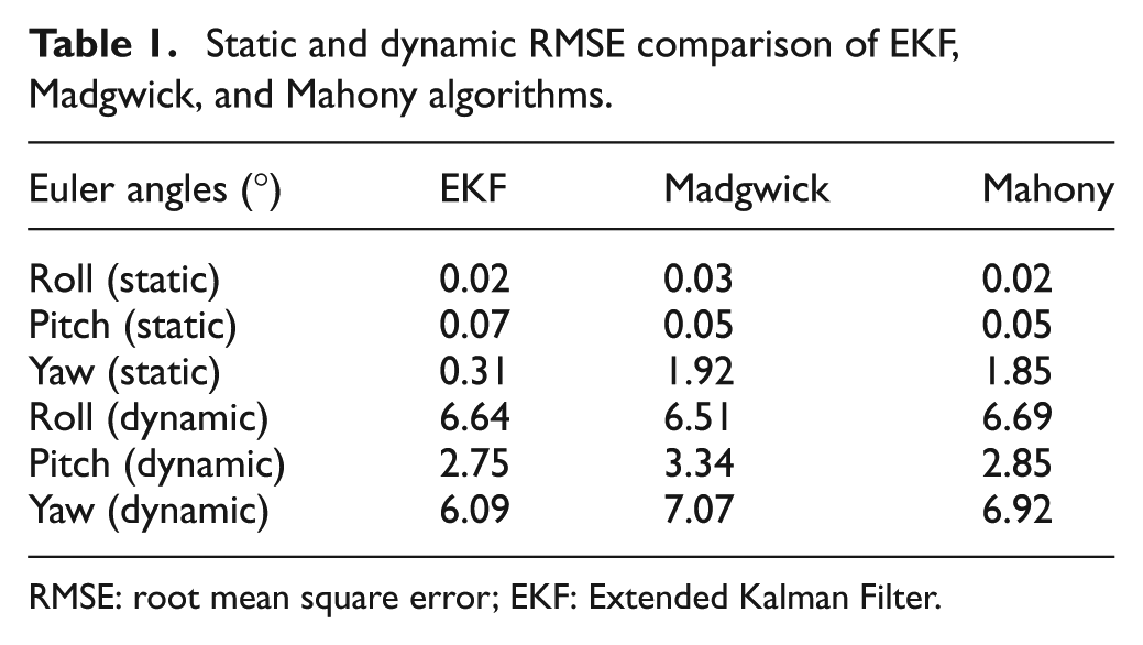
RMSE: root mean square error; EKF: Extended Kalman Filter.
Table 1 shows that the RMSEs of those three algorithms are generally higher in dynamic status, but it has a good effect when it comes to static status. In static status, the roll and pitch RMSEs of those three algorithms all have reached the level of 10−2; meanwhile, the yaw errors all are less than 2°. It also shows that the performance of the EKF algorithm in static status is superior to the other two algorithms in which RMSEs of roll, pitch, and yaw (RPY) are 0.02°, 0.07°, and 0.31° respectively. So in this article, we are going to use the EKF algorithm to obtain the exact pose measurement of our manipulator in the compensation experiment section. In addition, based on the curve analysis of actual test data we can see that during the course from dynamic status to static status, we can only achieve relatively stable measurement result of RMSE when there is a delay of 0.3 s of IMU measurement, as shown in Figure 8.
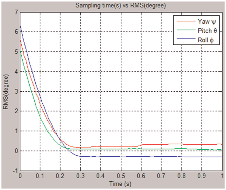
RMSE transition curve from dynamic status to static status.
Manipulator end-effector pose compensation
There are a lot of discussions on error compensation algorithm both in domestic and aboard. Ahmad 18 mounted sensors to each joint of manipulator and considered every influent factor in the transmission chain of manipulator. Error compensation data can be calculated by using sensor feedback information of each joint. Although the result of this kind of error compensation is good, its biggest disadvantage is that it highly raised the cost of the robot. Broderick and Cipra 19 proposed a method based on the shape matrix robot kinematic description to correct position and orientation errors. They analyzed every pose matrix of manipulator and explicitly calculate the shape matrix of each link. By using shape matrix, the geometric parameters of the link can be corrected to achieve error compensation. This method achieved certain compensation effect, but the effect is not very obvious. Veitschegger and Wu 20 developed a method of selecting a set of independent kinematic errors for modeling any geometric errors in a manipulator’s structure. The least square method and partial differential matrix equation of manipulator were used to solve the parameter error of various mechanism parameters; finally, the iteration method is also used to compensate for the error of the manipulator. The biggest problem of this method is that the algorithm is more complex, so it is not easy to use. Jiao et al. 21 proposed a numerical approach to calculate the numerical value for compensating synthetic pose errors of the robots. This method had a good compensation effect not only on the pure rigid body but also on the links and joints possess flexible situation, but they need to convert all error factors to structure parameters errors and motion variables errors, it is easy to lost and mistake during the process of conversion. Ligorio and Sabatini 22 proposed two approaches to fuse visual and inertial/magnetic measurements to track the ego-motion in all six DOFs with an IMU rigidly connected to the camera. Experiment result shows that one of the approaches (Direct Linear Transformation–based EKF) achieves good accuracy of pose estimation.
In this article, we proposed a new IMU-based iterative pose compensation algorithm. An IMU is rigidly mounted on the end of manipulator. With accurate pose measurement of IMU, we can get the actual pose of manipulator end-effector [R]. Target pose [G] is known in advance because it is our desired target. Then, error matrix [E] can be retrieved by error model which was mentioned in section “Manipulator error model.” The error matrix [E] can be used to compensate for the nominal pose [N] and feedback the compensation angles to control system. Here, nominal pose is an intermediate variable whose initial value equals [G]. Finally, the error will be reduced by iteration until the target accuracy is met. This algorithm does not need to consider the complexity of the joint structure parameters and motion parameters; it can be simple, intuitive, and quick to compensate for the error of the manipulator. Specific compensation process is shown in Figure 9. Because of the existence of errors, the actual pose is not equal to the nominal pose. The relationship is shown as equation (24)

Here “⊕” represents synthesis. The task of error compensation is to find such a nominal pose [N] so that it can synthesize with error pose [E] to get actual pose [R] which is exactly equal to the target pose [G] or within the allowable range.
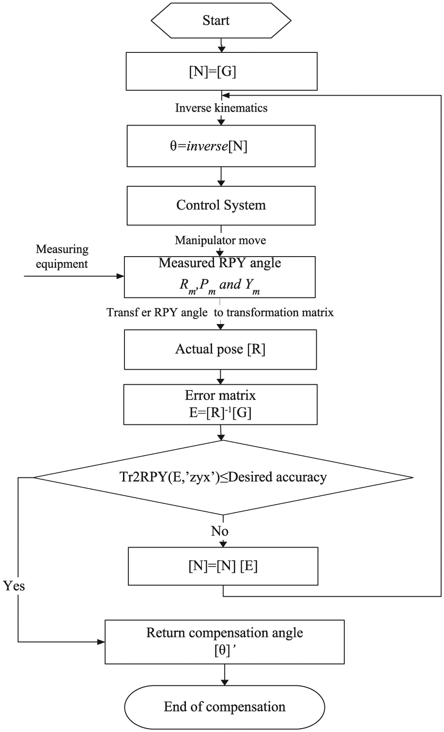
Process chart of manipulator end pose compensation.
The initial state of the nominal pose is equal to target pose

Due to the existence of errors, manipulator moves to the actual pose [R]1, and the value of [R]1 is obtained by IMU. According to the error model of equation (23), we can get error pose matrix [E]1

In order to make the actual position of manipulator equal to or close to the target pose, it needs nominal pose [N]1 to compensate through error pose [E]1; here we get

In theory, [N]2 is equal to the target pose, but the errors exist in the actual movement of manipulator. So, [N]2 and the error work together, and end-effector will reach the actual pose of [R]2; here the error pose is

So, we obtain the next iteration nominal pose

In the iterative process, the nominal pose [N] i will get close to the target pose step by step, and the compensatory angle of each joint will get smaller and smaller, that means the cumulative error which is caused by the rotation of motor will be reduced. So, the pose error of manipulator end-effector can be reduced, until it is stable within a certain tolerance range.
Experiment
WUST-ARM system structure
The WUST-ARM modular manipulator is a six-axis serial modular manipulator which is composed of six modular joints. Modular joint consisted of control circuit, encoder (Rotary encoder), motor (brushless DC motor), voltage: 24 V, coupled with a high rotation speed of 3000 r/min), and reducer (Harmonic reducer), and so on, as shown in Figure 10. Each modular joint is communicated by CAN bus, and the communication between the control system and the modular manipulator is achieved through USB port to CAN port. IMU is mounted on the end of manipulator gripper, IMU and control system is communicated through USB port. The system structure diagram is as shown in Figure 11.

Modular joint structure.

WUST-ARM system structure diagram.
WUST-ARM pose compensation experiment
The verification platform of this experiment is a six-axis modular manipulator WUST-ARM which consists of six low-cost rotation joints, to verify the compensation algorithm proposed in this article. We have known from section “IMU pose estimation” that IMU will get good pose measurement result in static condition. So we consider doing the static compensation on the control point of manipulation, it is that the manipulator will stop when arrive at the compensation point, by 0.3 s delay, start the compensation program when IMU is stable.
First, we assumed that the rotation angle of each joint of the modular manipulator WUST-ARM is

In this article, we proposed using iterative compensation algorithm to compensate for the end pose of WUST-ARM, which is based on IMU’s precise end-effector pose measurement, the error curve as shown in Figure 12. We can see from the figure that, by using this algorithm, it can make the error rapidly convergent. After three iterations, it can make the error tend to stabilize.
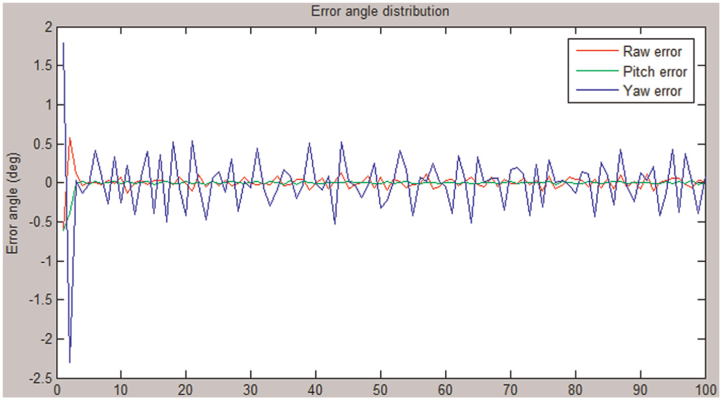
Error compensation curve of proposed iterative algorithm.
Pose comparison before and after compensation of WUST-ARM is shown in Table 2. From the table, we can see that the compensation effect is obvious. The RMSEs of RPY angles reduce from −0.60°, –0.61°, and 1.79° to 0.05°, 0.01°, and 0.27° respectively which approved effectiveness and robustness of this algorithm. It can also be found that the RMSEs of RPY angles after compensation are proportional to IMU’s accuracy which illustrates that compensation accuracy is decided by the precision of measuring instruments. So in this article, we compared the pose RMSE of our method with that of Ligorio and Sabatini 22 mentioned method (purely vision-based method and Direct Linear Transformation–based EKF method) in Table 3. By comparing the results in Table 3, the compensation results were more accurate in our method.
Pose RMSE comparison before and after compensation of WUST-ARM.

RMSE: root mean square error.
Pose RMSE comparison between our method and Ligorio and Sabatini 22 method.

RMSE: root mean square error; DLT: Direct Linear Transformation.
Conclusion and future work
In this article, first, we discussed the method of real-time kinematics solution and error representation by analyzing the kinematics model and the error model of the modular manipulator WUST-ARM. Then we analyzed the method to obtain the precise pose estimation of IMU, EKF fuse algorithm is used to fuse the raw data of IMU, and get the pose output. The results show that the IMU can get accurate pose measurement when in static condition, and RMSEs of RPY can reach 0.02°, 0.07°, and 0.31° respectively. At the same time, it shows that the system need about 0.3s to stabilize the measurement during the course from dynamic status to static status, so the control strategy is proposed: the compensation program is started at the control point by 0.3s’ delay when the measurement of IMU is stable. In the actual application of our WUST-ARM, the experimental results show that the manipulator end-effector pose can be converged after three times of iteration, and the RMSEs of RPY angles reduce from −0.60°, –0.61°, 1.79° to 0.05°, 0.01°, 0.27° respectively. The entire compensation process is automated, no need of human intervention, and proved to be effective and robust. The proposed algorithm can compensate and correct the manipulator end-effector pose simply, intuitively, autonomous online and low cost. It provided a new solution with low cost for improving the control precision of modular manipulator. Next, we will focus on how to achieve accurate and effective dynamic pose compensation in the process of modular manipulator movement without a brief time pause.
Footnotes
Academic Editor: Yong Chen
Declaration of Conflicting Interests
The author(s) declared no potential conflicts of interest with respect to the research, authorship, and/or publication of this article.
Funding
The author(s) disclosed receipt of the following financial support for the research, authorship, and/or publication of this article: This work was supported by National Natural Science Foundation of China (grant no. 61175094).