
Abstract
Thermal-hydraulic analysis of plate-type fuel has great importance to the establishment of safety criteria, also to the licensing of the future nuclear reactor with the objective of propelling the Brazilian nuclear submarine. In this work, an analysis of a single plate-type fuel surrounding by two water channels was performed using the RELAP5 thermal-hydraulic code. To realize the simulations, a plate-type fuel with the meat of uranium dioxide sandwiched between two Zircaloy-4 plates was proposed. A partial loss of flow accident was simulated to show the behavior of the model under this type of accident. The results show that the critical heat flux was detected in the central region along the axial direction of the plate when the right water channel was blocked.
Introduction
Currently, plate-type fuel is widely used in research reactors (RRs) as well as in the core of nuclear submarines (SSN).1–4 An analysis to assess the trade-offs involved in the use of highly enriched uranium (HEU) versus low enriched uranium (LEU) as SSN reactor fuel, regarding to factors as core life, core size, and reactor safety was conducted by Ippolito Jr. 1 It was accomplished by modeling one HEU and two LEU reactor cores for comparison. Besides, in this study, it was determined that the plate-type fuel with the fuel device made of uranium dioxide (UO2) sandwiched into two Zircaloy-4 plates is more qualified to support the high degree of requirements to power SSNs.
According to Duderstadt, 5 a more critical limitation is the heat flux that can be transferred from the clad to the coolant in water-cooled reactors, for example, pressurized water reactor (PWR) or boiling water reactor (BWR). This thermal limitation, known as critical heat flux (CHF), is of primary concern in water-cooled reactors cores in which the coolant temperature is allowed to approach the boiling point. The CHF has been the subject of research in the field of boiling heat transfer by nuclear engineers for many decades. 6
As evidenced by Collier and Thome, 7 the critical heat flux condition (CHFC) is characterized by a sharp reduction of the local heat transfer coefficient, which results from replacement of liquid by vapor adjacent to the heat transfer surface. Taking the case where the surface heat flux can be the independent variable, the condition manifests itself as a sharp increase in surface temperature when the CHF value is reached. In the literature, a considerable disparity in nomenclature for the CHFC can be observed. The most common name is “burnout,” but this implies a physical destruction of the heat surface. However, the most measurements of the “burnout heat flux” are, in fact, measurements of the heat flux at which a sharp rise in surface temperature takes place and, as has been reported by Collier and Thome, 7 melting of the heated surface would not necessarily be expected to occur at the same flux level. Another alternative forms “departure from nucleate boiling” (DNB) and “dryout” are equally unsatisfactory for a general description of the phenomenon since they imply definite mechanisms. Thus, the CHFC has been chosen by Collier and Thome 7 to denote the state of the system when the characteristic reduction in heat transfer coefficient has just occurred and the term CHF to describe the value of heat flux to the point where this state of the system first occurs.
Above certain heat flux magnitudes, the heat transfer to the coolant becomes unstable as a film of vapor forms to cover the fuel element surface. At this point, the clad temperature will increase dramatically (several hundred degrees) leading to clad failure. 5 A study was conducted by Blanchat and Hassan 6 in order to predict the behavior of the secondary side of the steam generator using the RELAP5/MOD2 computer code and, in particular, to obtain a better prediction of CHF in bundles.
In general, the transients limits in PWRs to be considered include a loss of coolant accident (LOCA), an overpower transient, and a loss of flow accident (LOFA). 8 The LOFA also consists of two categories: the complete loss of flow accident (CLOFA) and the partial loss of flow accident (PLOFA). LOFA simulations have been limited so far to the investigation of protected transients only. 9 With the reactor shutdown system enabled, all LOFA simulations predict that clad temperature remains well below the clad melting point and that no flow instabilities take place in the cooling channels. The RR safety calculations entail usually the simulation of several selected cases within two broad accident categories, namely, re-activity insertion accidents and LOFAs. In the work of Housiadas, 9 it was investigated through numerical simulations the course of unprotected loss-of-flow transients in a typical pool-type RR. A sensitivity analysis of the loss of forced flow accident due to pump stop as a result of loss of the electricity supply for the IRT-Sofia was investigated by Belousov. 10 PARET code was used by Huda et al. 11 to analyze two most important thermal-hydraulic design parameters of the 3 MW TRIGA MARK RR. The first design parameter is the departure from nucleate boiling ratio (DNBR), which is defined as the ratio of the CHF to the heat flux achieved in the core. The second design parameter is the LOFA scenario of the TRIGA reactor.
The RELAP5 is a highly generic code that in addition to calculating the behavior of a reactor coolant system during a transient, it can be used for simulation of a wide variety of hydraulic and thermal transients in both nuclear and non-nuclear systems, involving mixtures of steam, water, non-condensable, and solute. 12 RELAP5 was initially designed to thermal-hydraulic analysis and simulation of commercial power reactors. In recent works, the code was used to thermal-hydraulic analysis of RRs.13–17
According to RELAP5 manual, a table lookup method developed by Groeneveld, Cheng, and Doan is used for the prediction of the CHF. Code users also have the option of using a CHF correlation developed by the Czech Republic. When the wall superheat exceeds the critical value, the heat flux for both the transition boiling and the film boiling regimes are calculated and the maximum value is used. This eliminates the need for a prediction of a minimum film boiling temperature. The Chen–Sundaram–Ozkaynak correlation is used for transition boiling and a modified Bromley correlation is used for film boiling. In the RELAP5, the subroutine CHFCAL determines the CHF. 12
In past, huge effort was done by Organization for Cooperation and Development/Nuclear Energy Agency/Committee on the Safety of Nuclear Installations (OECD/NEA/CSNI) from 1991 to 1997 in the construction of the Separate Effects Test Facility Code Validation Matrix (SETF-CCVM, published in 1994) for thermal-hydraulic system codes, as described by Aksan et al. 18
An integral test facility (ITF) matrices for validation of realistic thermal-hydraulic system computer codes were also established by CSNI focused mainly on PWRs and BWRs. In all, 187 facilities covering 67 relevant phenomena for LOCA and non-LOCA transient applications of PWRs and BWRs within a large range of useful parameters were identified and about 2094 tests were included in the SETF-CCVM matrix. The majority of these phenomena are also relevant to advanced water-cooled reactors. The major elements of the SETF-CCVM have been already integrated into the validation matrices of the major best-estimate thermal-hydraulic system codes, for example, TRAC, RELAP5, CATHARE, TRACE, and ATHLET. And the full exploitation of these advanced best-estimate system codes, which are strictly based on two-fluid representation of two-phase flow and a best-estimate description (in contrast with the evaluation models which used many conservative assumptions) of complex flow and heat transfer conditions, implies mainly their acceptability by the licensing authorities. 19
In thermal design reactors, the use of thermal-hydraulic loops, with electrically heated rods which simulate operational and accident conditions of nuclear fuel rods, is of universal practice. These simulations represent one of the most important aspects in the analysis of safety of a reactor. 20
Currently, an experimental electrical heating section of tests is being prepared by Brazilian Navy to start the simulation of CHF. The main goal is the analysis of the thermal-hydraulic limits of the project in order to obtain the license to operate the Brazilian Reactors. The electrical heating section will be tested with an estimated power generation of 0.30 MW. The ITF will be hired by the Brazilian Navy and will be conducted by the University of Pisa. After collecting and tabulating the data, the next step of this study is to propose correlations between the real model and the simulated theoretical model using thermal-hydraulic codes as RELAP5 software.
In this work, an analysis of a plate-type fuel surrounded by two water channels was performed, considering the fuel device made of uranium dioxide (UO2) and sandwiched between two Zircaloy-4 plates. The simulations were carried out using the RELAP5/MOD 3.3 to solve the equations of the theoretical model. A PLOFA was simulated to show the behavior of the model in this severe type of accident. The results show that the CHFC was reached in the system and the maximum CHF was detected in the central region of the plate.
Theoretical model
In Figure 1(a), a theoretical model of plate-type nuclear fuel with 17 elements welding in 2 side plates is depicted. Also Figure 1(b) shows one fuel plate surrounded by two coolant channels. In this model, it was considered that the fuel device is built with uranium dioxide (UO2), sandwiched between two Zircaloy-4 plates. The heat generated into fuel was transferred through the meat cladding by conduction and through the coolant by convection. 3

Theoretical model: (a) plate fuel elements, plan view, (b) one plate, plan view, and (c) one plate discretization.
Plate-type fuel temperature distribution
In accordance with Duarte et al. 2 and Khedr, 3 the one-dimensional heat conduction equation through the unit fuel plate in Figure 1(c), is given in equations (1) and (2)


The boundary conditions are given in equations (3)–(6)


where
Temperature of coolant
The distribution of the coolant axial temperature is calculated by Khedr 3 in equation (7)

where
Heat transfer coefficient
RELAP5 uses the Dittus–Boelter correlation selected by default; others are available by user selection as Churchill–Chu, Kays, Shah, McAdams, and Engineering Science Data Unit (ESDU).
The heat transfer coefficient was calculated through Dittus–Boelter correlation (equation (8)) 2

where
When a user of RELAP5 selected a solid surface in the input deck by means of setting the word W3(I) in the Card Number 1CCCG501-599 that sets the left boundary condition or, the word W3(I) in the Card Number 1CCCG601-699 that sets the right boundary condition as having a convective boundary condition, the heat transfer coefficients are calculated and passed to the conduction solution. The liquid and vapor/gas energy solutions include the wall heat flux to liquid or vapor/gas. The experimental coefficients used to develop correlations were determined by obtaining the experimental heat flux and dividing it by a wall-to-reference-temperature difference. Consequently, when the correlations are used to obtain the code-calculated heat flux, they use the same reference temperature as the correlation developer used. Internally, the heat transfer coefficients are determined in one of five subroutines: DITTUS, PREDNB, PREBUN, PSTDNB, and CONDEN. Subroutine CONDEN calculates the coefficients when the wall temperature is below the saturation temperature based on the partial pressure of vapor. Subroutine DITTUS is called for single-phase liquid or vapor/gas conditions. Subroutine PREDNB contains the nucleate boiling correlations for all surfaces except horizontal bundles and subroutine PREBUN is used for the outer surface of horizontal bundles of rods or tubes. Subroutine PSTDNB has the transition and film boiling correlations. 12 By the options selected in this work, the heat transfer coefficients were obtained by the Dittus–Boelter correlation.
To solve this set of partial differential equations that represent the theoretical model, in general case, a finite difference method or finite volume method approach is applied.
Nodalization model
In order to analyze the thermal-hydraulic behavior of the theoretical model, a RELAP5 input deck and nodalization for the one single plate was designed and, in accordance with Todreas and Kazimi 21 to the case of a homogeneous unreflected core, the whole core can be considered as one fuel element. This assumption was considered in this work to the conception of the theoretical model.
The nodalization diagram can be seen in Figure 2. Two pipe components represent the water channels surrounding the one heat structure component. This model was divided in 12 nodes along the axial direction of the channels (pipe component) and 12 mesh points along the radial axis of the plate fuel (heat structure component). A trip valve component was used to simulate a flow blockage in the right channel of the system, representing a PLOFA.
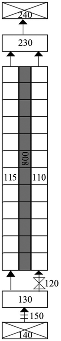
RELAP5 nodalization model.
A short description of the components with the identification numbers and types is presented in Table 1.
Main components of the nodalization.

The main physical data for the simulations are listed in Table 2 where the measures are in millimeters, and are in accordance to Ippolito Jr
1
as well as the initial conditions for the simulation. The heat generation was 0.30 MW and the initial flow velocity was 2.7 m/s. The system had a constant pressure of 15.0 MPa, typical in PWR reactors. The inlet/outlet temperatures are 563°K and 593°K, respectively. The core temperature was 583°K. The pressure drop is equal for the two channels. In the simulation, the Reynolds Number is 5.48336E + 06 and it can be found in the output data file generated by RELAP5 code. When applied the relation
Main physical data for the simulations.

Numerical simulations results
In this section, the results are shown considering that in the left channel, the behavior of the plate fuel is studied without channel blockage and in the right channel, with the valve blocked to simulate a channel blockage as a PLOFA. All the simulations were carried out with time span of 1500 s. To simulate a PLOFA, the component valve was driven at 500 s of simulation time, causing the total blockage of the flow of water in the right channel.
Figure 3 presents the temperature of the heat structure, where the increase in the values occurred at 500 s of simulation. The variable htvat represents the volume averaged temperature in the heat structure component with nodalization number 800. The temperature is the medium value measured between the two sides of the heat structure along the radial axis. In Figure 3, the htvat-06 and htvat-07 nodes are the central points of the plate fuel along of the axial axis, where the power generation is larger.

Temperature of the heat structure.
In Figure 4, some points of the fluid temperature were picked and plotted in order to demonstrate the effect of PLOFA. The tempf-11001 is the first volume of the PIPE 110 (inlet) and tempf-11012 is the latest volume (outlet) of the right channel. At 500 s of simulation, an increase of approximately around 20°K occurs. On the other hand, in the left channel PIPE 115, the tempf-11501 (inlet) and tempf-11512 (outlet) do not present significant variation in the temperature, with the values remained near to the initial condition temperature of the source found in the TMDPVOL component with the number 140 (tempf-14001 in Figure 4). The sink of the theoretical model is the TMDPVOL component with the number 240 (tempf-24001 as can be seen in Figure 4).
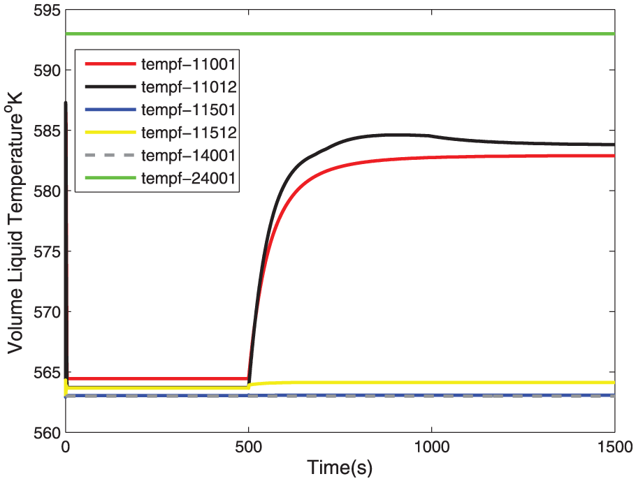
Volume liquid temperature.
The heat transfer coefficients (Figure 5) present a great variation in the case of a right channel blockage at 500 s of simulation. The variable hthtc represents the heat transfer coefficients in the heat structure component with the number 800. The hthtc-800100100 (first volume) and hthtc-800101200 (last volume) show the heat transfer coefficients values of the heat structure over the left surface area, where its behavior remains stable. The hthtc-800100101 (first volume) and hthtc-800101201 (last volume) show the heat transfer coefficients values of the heat structure over the right surface area, where an abrupt decrease in the heat transfer coefficients occurs in the case of PLOFA.

Heat transfer coefficients.
In the RELAP5, the variable htchf stores the values of the CHF calculated by the simulation. These values are depicted in Figure 6, where the htchf-800100600 and htchf-800100700 are the central mesh points in the left side of the heat structure and, with the normal flow in the channel no CHF occurs along the time of simulation. On the other hand, where the htchf-800100601 and htchf-800100701 are the central mesh points in the right side of the heat structure, the channel blockage causes the heat structure temperature increases at the point where the CHF occurs. In this condition of instability, the fuel heat could not be retired and the melting point of the fuel could be reached.

Critical heat flux.
The critical heat flux ratio (CHFR) in Figure 7 is the ratio between the CHF and the local heat flux. This term is a measure of the margin to DNB, an important criterion to limit the maximum power of the reactor core design. In the RELAP5, the variable htchfr stores the values of CHFR. In this case, the htchfr-800100600 and htchfr-800100700 are in the central point of the heat structure over the left side surface area and, presents the value of 0. The htchfr-800100601 and htchfr-800100701, in the central point of the heat structure over the right side surface area, achieved larger values after the channel blockage at 500 s of simulation. One hypothesis to this result could be associated with the application of a chopped cosine profile of power to the heat structure.

Critical heat flux ratio.
Figure 8 depicted the distribution of fuel plate temperature when the flow of the coolant is normal for both channels. Along the fuel thickness axis, the distribution of the temperature over the 12 mesh points can be verified. The intense red color represents the central region of the plate. The power profile imposed on the system, in the form of a cosine chopped, influences the distribution of the data presented in Figure 8. At the height of the active heat structure, the distribution of temperature likewise in the thickness remains concentrated in the central volumes of the both channels. The MATLAB datatips depicted on the borders show the temperature in the surface area on the left and on the right side of the fuel plate. The temperature presents an equal value of 582.9°K. It is achieved because the coolant flows normally along the channels.

Fuel plate temperature distribution.
Figure 9 depicts the fuel plate temperature distribution when the flow of the coolant is blocked in the right channel to simulate the hypothesis of a PLOFA scenario. Along the fuel thickness axis, the distribution of the temperature over the 12 mesh points, presents a growth in the direction of the right surface area of the plate fuel. The intense red color that represents the larger temperature is depicted in the extreme mesh point at the right region of the plate with the value of 615.8°K. The profile of power distribution no longer presents a cosine form. In the height of the active heat structure, the temperature distribution no longer presents equal concentration in the central volumes of the both channels. The temperature presents a value of 602.5°K in the left surface of the heat structure. Clearly, the blockage of the right channel coolant flow also causes the elevation of the temperature in the left channel because of the conduction of the heat from one side to the other of the plate. The increase in the temperature of the heat structure for the case where the right channel was blocked achieves 5.62% higher rather than the case without the channel blockage.

Fuel plate temperature distribution.
Conclusion
Thermal-hydraulic analysis is of fundamental importance to conduct nuclear experiments and the RELAP5 code is a powerful tool to perform such analysis. In this work, the analysis of a single plate-type fuel surrounded by two water channels shows the capabilities of the RELAP5 code to perform transient analysis and to simulate a PLOFA severe accident. As shown, when the valve blocked the water flow, the heat removal by the coolant was decreased and the CHF has occurred on the right surface of the heat structure. The increase in temperature on the right side has influenced the temperature of the left side by heat conduction, but no hot spots were detected on the left side of the plate. In the real scenario, this could be the cause of the melting of the core.
Footnotes
Academic Editor: Bo Yu
Declaration of Conflicting Interests
The author(s) declared no potential conflicts of interest with respect to the research, authorship, and/or publication of this article.
Funding
The author(s) received financial support of the São Paulo Research Foundation - FAPESP - Project No. 2010/11113-2 and University of São Paulo.