
Abstract
Through the analysis of the control theory for steam turbine, the transfer function of the steam turbine control modes in the parallel operation was obtained. The frequency domain analysis indicated that different control modes of turbine control system have different influence on the damping characteristics of the power system. The comparative analysis shows the direction and the degree of the influence under the different oscillation frequency range. This can provide the theory for the suppression of the low-frequency oscillation from turbine side and has a guiding significance for the stability of power system. The results of simulation tests are consistent with the theoretic analysis.
Introduction
In recent years, with the increase in power demand, the size of power system has improved and the transmission power in main lines is increasing. In this case, the entire power system operating conditions are becoming increasingly worse and low-frequency oscillation occurs frequently. Low-frequency oscillation has become one of the most important factors to restrict power transmission and also the safe and stable operation of power system.
Negative damping theory is the most acceptable mechanism for the occurrence of low-frequency oscillation. In 1969, the American scholar Demello FP and Concordia C analyzed and interpreted the causes of low-frequency oscillation in the single-machine infinite-bus system using the concept of damping torque. The research shows that the quick excitation system with high magnification can make the system produce negative damping torque. The negative damping torque can counteract the positive damping of the system and make the system damping turn to negative. This likely leads to insufficient damping torque of system and the occurrence of low-frequency oscillation. 1 But this explanation ignored that the turbine control system can also have an impact on the damping of power system. In fact, some articles had pointed out this correlation. FR Schleif et al. 2 had done the research about improving the system damping by the turbine control system as early as 1967. Moussa and Yu 3 verified the relationship between turbine controller and system damping on water turbine unit through digital simulation method. Limited by the performance of equipment, the response time of turbine control system was very slow at that time, the impact of the control system on damping was not obvious, and the reliability was also a big problem, so this research was not proceeding. Besides that, many scholars turned their attention to the generator excited system which has more obvious effects on the damping of power system. Based on different algorithms, the literature4–8 pointed out the ways to design a power system stabilizer or excitation controller to control the low-frequency oscillation under different conditions. The results of these research achieved good effect in theory. However, due to the swift development of thermal power generation control technology, the response time of turbine control system is faster and faster, and the low-frequency oscillation accidents caused by the prime mover side is more and more frequent. This proved that the influence of prime mover side on the system damping should not be ignored. Based on negative damping mechanism, the literature8–10 studied the influence of the turbine control system on low-frequency oscillation. It showed that the turbine control system can provide a negative damping torque to the system. This may cause the low-frequency oscillation of the grid. The literature8,9 analyzed the influence of the main parameters on the damping characteristics of the grid. The literature 10 pointed out that if the regulator parameters were improper, they could cause the low-frequency oscillation of the grid. The literature11,12 pointed out that through changing the turbine control system operation mode, the purpose of online low-frequency oscillation suppression could be achieved. But these conclusions lack theoretical derivation.
This article established the mathematical models of power system in a variety of steam turbine (digital electric hydraulic (DEH)) system control modes. Through the frequency analysis of transfer functions, the influence of control mode on the damping characteristics and stability of the grid was studied. In order to verify theoretical analysis, the simulation tests in single-machine infinite-bus system model and two-machine five-node system were carried out.
Control modes of steam turbine DEH
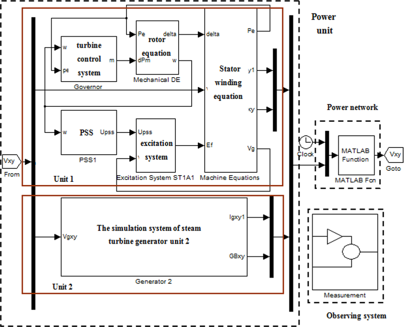
When the steam turbine generator units are dived into network operation, the steam turbine is controlled by the DEH system. In this case, power and frequency are the controlled variables. Generally speaking, the DEH system includes four kinds of control modes, namely, open-loop control mode, power feedback control mode, governing stage pressure feedback control mode, and coordinated control mode. Because the controller of coordinated control mode is located in the coordinated control system (CCS), it is beyond the scope of this article, but it can refer to the conclusion of the power feedback control mode.
The diagram of different control modes of DEH is shown in Figure 1, where ω and ω 0 are the frequency feedback signal and demand frequency, respectively; PM and PE are the mechanical and electromagnetic power, respectively; Pref is the power reference; PT is the governing stage pressure; TD is the control signal from the CCS system; V is the valve opening demand given by operator; Tω is the time constant of speed transducer; R is the speed droop; Kp, Ki , and Kd are the parameters of proportional–integral–derivative (PID) controller; and GE and GT are the transfer functions of actuator and steam turbine, respectively.

The diagram of different control modes of DEH.
The output signal of the DEH system is transformed into opening demands of valve by the actuator, and then the output of unit is changed.
The actuator is composed of electric hydraulic servo and oil motive. As shown in Figure 2, PCV is the control signal from DEH; PGV is the output valve opening from the oil motive; Kp 1, Ki 1, and Kd 1 are the parameters of valve controller; Tc and To are the closing and opening time interval of oil motive, respectively; T 2 is the time constant of linear displacement sensors; Tch, Trh , and Tco are time constants of the inlet chamber, reheater, and cross tube system, respectively; Fhp, Fip , and Flp are the portion of power produced by high, intermediate, and low pressure cylinder, respectively; λ is the natural overcorrection coefficient of high pressure cylinder; H is the inertia constant of rotor; and KD is the damping torque coefficient. Ignoring the nonlinear components, the transfer functions of the model can be derived as follows


The mathematical model of actuator and steam turbine.
Open-loop control mode
Open-loop control mode is also known as “valve position control” or “manual control” mode. Under the open-loop control mode, the operator gives the opening demands directly, and then DEH outputs the valve opening signal to the valve control card. Through comparing with valve position feedback signal, the valve control card outputs the control signal to the oil motive, and then the valve opening is changed.
The transfer function of open-loop control model can be derived as follows

Power feedback control mode
In power feedback control mode, the power controller is working. At first, DEH receives the active power feedback signal, and then the power controller outputs a valve opening signal according to the difference between feedback signal and power demand. The valve opening signal is sent to valve control card to change the valve opening. By controlling the opening of valve, the required power is achieved.
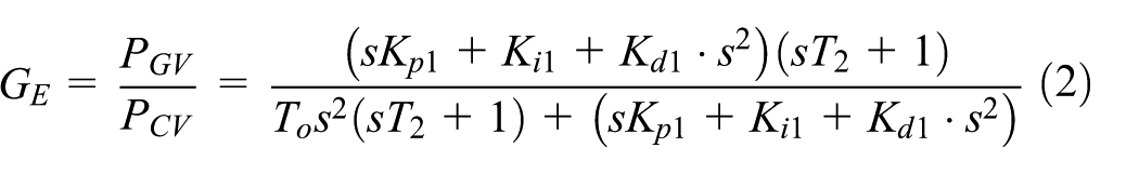
The transfer function of power feedback control model can be derived as follows

In equation (6), there are two input sources in the system, namely, ω and PE. GGOV 1 and GGOV 2 are the transfer functions of two inputs to PM .
Note that turbine output mechanical power is changed through changing the opening of valve. In the dynamic process, the mechanical power and electromagnetic power may not be equal. This is because there are two torques acting on the rotor: one is the turbine output mechanical torque which is an active torque and the other one is electromagnetic torque which can hinder the rotor rotation. When the mechanical torque increases with the electromagnetic torque remaining the same, the rotor will spin up. After a period of time, the electromagnetic torque will increase gradually until equal to the mechanical torque through a series of magnetic chain reaction, and the rotor will reach a new equilibrium position. Therefore, there is a certain lag by adjusting the turbine mechanical power to regulate the output; this will cause additional impact on the damping characteristics of the power system.
Governing stage pressure feedback control mode
According to the logic setting of the DEH control system, there is only one control mode which can be put into service among the power feedback control mode and the governing stage pressure feedback control mode. In the governing stage pressure feedback control mode, the governing stage pressure controller is working. Through the comparison between the governing stage pressure feedback signal with the given value, the pressure controller outputs a signal to change the opening of the valve. In this way, the governing stage pressure can achieve the given value.
The transfer function of the governing stage pressure feedback control mode can be derived as follows

Analysis of damping characteristics under different control modes
Analyzing the frequency domain with the formula s = jw taken into equations (5)–(7)

As shown in equation (8), Ks and KD are the synchronization torque coefficient and the mechanical damping torque coefficient, respectively. It is easy to find that the damping offered to the electric power system by turbine regulating system is related with its parameters and oscillation frequency. Through the control of ΔPm , a mechanical power (torque) is produced. If the mechanical power ΔPm is reverse to Δωm , it will increase the damping of the system. Conversely, it will weaken the damping of the system.
According to equation (5), in open-loop control mode, the transfer function of mechanical power only associates with the valve position command and has nothing to do with frequency ω. So the steam turbine control system will not affect the damping of the system in open-loop control mode. Therefore, only the damping characteristics of the power feedback control mode and governing stage pressure feedback control mode are taken into the analysis.
In power feedback control mode, the transfer function is composed of two parts according to equation (6). So the damping characteristics of the grid are produced by the superposition of the two parts. The transfer function of grid adopts the single-machine infinite-bus system model as shown in equations (9) and (10)


We can achieve equation (11) as follows

Equation (12) can be derived as follows

Taking the values of the model parameters into equations (7) and (12), we acquired the real part and imaginary part of the transfer function. The real part indicates the size of mechanical damping torque coefficient of the steam turbine control system. Through drawing out the power system damping characteristic curve, the effects of the steam turbine control modes on the damping characteristics can be analyzed.
The model parameters used in calculation are shown in Tables 1 and 2. The mechanical damping torque coefficient curve is shown in Figure 3.
Typical parameters of the steam turbine control system.

Typical parameters of the single-machine infinite system.


Effects of different control modes on the damping characteristics of the grid.
In Figure 3, the following conclusions can be achieved. (1) The steam turbine control system will not affect the damping of the system in open-loop control mode. (2) In the whole frequency range of low-frequency oscillation, both the power feedback control mode and the governing stage pressure feedback control mode have an effect on the damping of grid. (3) There is a boundary frequency which exists in both the power and the governing stage pressure feedback control modes. The steam turbine control system provides negative damping to the grid when the oscillation frequency is higher than the boundary frequency and provides positive damping to the grid when the oscillation frequency is lower than the boundary frequency. (4) Compared with the governing stage pressure feedback control mode, the power feedback mode has a stronger effect on the damping of gird. (5) The boundary frequencies of the two modes are different. When controller parameters are the same, the boundary frequency of the governing stage pressure feedback control mode is higher, so this control mode can provide positive damping to the grid within a broader frequency range.
Simulation research
The grid adopts the single-machine infinite-bus system model as shown in Figure 4. ΔTm is the mechanical power increment. ΔTe is the electromagnetic power increment. Δδ is the rotor angle increment. ΔVref is the reference voltage increment of voltage regulator. ΔV 1 and ΔE 1 are the voltage signals. ΔΨfd is the excitation loop flux increment. ΔEfd is the exciter output voltage increment. T 3 is the excitation circuit time constant. TR is the time constant of voltage sensor. Gov (s) is the exciter proportion coefficient (denoted as KA ). K 1, K 2, K 3, K 4, K 5, and K 6 are the proportionality coefficients. Set the above parameters as the typical values. 13

Single-machine infinite-bus system model.
Zero-pole of the system can be obtained using the control system’s toolbox in MATLAB. By analyzing the zero-pole, the oscillation mode in three control modes is acquired, as shown in Table 3.
Oscillation mode in the three control modes.

In the open-loop mode, there is a low damping oscillation mode with frequency of 1.3 Hz and damping ratio of 0.164, but the steam turbine control system will not affect the damping of the system in open-loop control mode.
In the power feedback mode, there is an oscillation mode with frequency 1.39 Hz. As shown in Figure 3, within the frequency range of 1.0–1.49 Hz, the steam turbine control system will provide a negative damping to the grid; the damping ratio of the system is −0.011 when frequency is 1.39 Hz.
In the governing stage pressure feedback control mode, the frequency of the oscillation mode is 1.37 Hz. As shown in Figure 3, within the frequency range of 1.0–1.49 Hz, the steam turbine control system will provide a positive damping to the grid; the damping ratio of the system is −0.011 when frequency is 1.37 Hz.
When disturbance of mechanical power occurs in 4 s with its value 0.01 per unit, the generator electric power response of the three control modes is shown in Figure 5.

Generator electric power response curve.
As can be seen from Figure 5, in open-loop mode, a low damping frequency oscillation occurs in the system; in power feedback mode, the damping of the system decreased below zero, and a negative damping frequency oscillation occurred in the system; in governing stage pressure feedback control mode, the damping of the system increased, and the stability of the system was enhanced. The simulation results are consistent with the analysis.
Using the power system simulation model provided by power system simulation toolbox (PSST) 14 to build a two-machine five-node system model, the model is shown in Figure 6.
Simulation model of the two-machine five-node system.
At the time of 0.5 s, three-phase short circuit fault happened in the fourth bus. After 0.06 s, the fault line is removed and the PSS is put into service. The simulation results are shown in Figure 7, and the oscillation modes of three control modes are shown in Table 4.

Generator electric power response curve.
Oscillation mode in the three control modes.
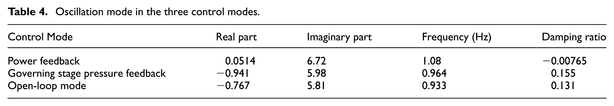
In the open-loop mode, the damping ratio of its oscillation mode is 0.131. If the control mode is selected as the governing stage pressure feedback mode, there is an oscillation mode with frequency of 0.964 Hz, and the control system provides positive damping to the grid; the amplitude of oscillation is smaller. If the control method is selected as the power feedback mode, there is an oscillation mode with frequency of 1.08 Hz, and the control system provides negative damping to the grid; the amplitude of oscillation is larger. In summary, the simulation results of the two-machine five-node system are consistent with previous analysis.
According to the simulation results, it is known that varying degrees of electric power oscillation can be induced when the fault occurs in three different control modes. The electric power feedback mode can decrease the damping of the system and cause negative damping low-frequency oscillations at a certain oscillation frequency. The governing stage pressure feedback mode can increase the damping of the system and suppress low-frequency oscillations at a certain oscillation frequency. The open-loop mode will not affect the damping of the system.
Summary
When the steam turbine generator units are dived into network operation, there are three different control modes in DEH. The influences of turbine control system on power system are different in different control modes. The frequency analysis of mechanical damping torque coefficient shows that the turbine control system has an obvious effect on damping of grid in the whole low-frequency oscillation range. Through the analysis of the typical systems and data, it is known that the steam turbine control system will not affect the damping of the system in open-loop control mode; there is a boundary frequency, which the steam turbine control system provides negative damping to the grid when the oscillation frequency is higher than the boundary frequency and provides positive damping to the grid when the oscillation frequency is lower than the boundary frequency. By comparison of the three modes, the governing stage pressure feedback control mode can provide a bigger positive damping to the grid within a broader frequency range; its suppression for low-frequency oscillation is better than the electric power feedback mode and also the open-loop mode. Simulation results in single-machine infinite-bus system model and two-machine five-node system were consistent with theoretical analysis. This conclusion provides a useful reference for suppression of low-frequency oscillation from turbine side, and it has an important significance for reducing the incidence of low-frequency oscillation.
Footnotes
Appendix 1
Academic Editor: Sergio Nardini
Declaration of conflicting interests
The author(s) declared no potential conflicts of interest with respect to the research, authorship, and/or publication of this article.
Funding
The author(s) disclosed receipt of the following financial support for the research, authorship, and/or publication of this article: This work was supported by the National Basic Research Program of China (Project No. 2015CB251504).