
Abstract
This article presents a new dynamic motion stabilization approach to front-wheel drive in-wheel motor electric vehicles. The approach includes functions such as traction control system, electronic differential system, and electronic stability control. The presented electric vehicle was endowed with anti-skid performance in longitudinal accelerated start; smooth turning with less tire scrubbing; and safe driving experience in two-dimensional steering. The analysis of the presented system is given in numerical derivations. For practical verifications, this article employed a hands-on electric vehicle named Corsa-electric vehicle to carry out the tests. The presented approach contains an integrated scheme which can achieve the mentioned functions in a single microprocessor. The experimental results demonstrated the effectiveness and feasibility of the presented methodology.
Keywords
Introduction
Due to the demands on pollution-free and quieter driving experiences, the electric vehicles (EVs) have become a popular investigation topic. From the viewpoint of drive-train (or say power-train), as depicted in Figure 1, EVs can be classified into two types as follows:
Power centralized;
Power decentralized.
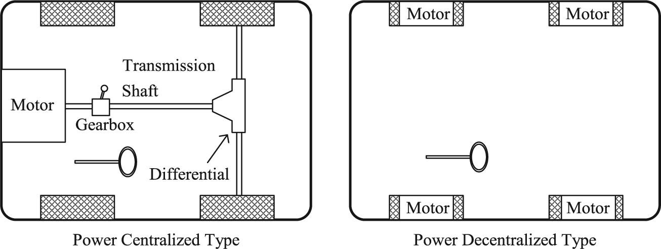
Classification of electric vehicles.
The drive-train of the first type EV is the same as the conventional internal combustion engine vehicles. Mechanisms such as gearbox, clutch, differential, and shaft are employed for power distribution. The only difference is that the engine was replaced by a centralized electric motor and the fuel tank was acted for electrochemical battery. The second type is famous as the in-wheel motor EVs. The in-wheel motor EVs are powered by independently equipped motors to drive each wheel. 1 For urban sedans, there are always two driving styles formed, that is, two-wheel drive (front-wheel drive or rear-wheel drive) or four-wheel drive. No matter what kind of the drive styles, due to the lack of mechanism supporting, the power decentralized systems require more advanced technologies to ensure the dynamic stability of the steering. For example, the adaptive front-lighting system (AFS) 2 is employed for the safe night driving, the electronic differential system (EDS)3,4 is utilized for a smooth turning with less tire scrubbing, and the slip prevention technologies such as the antilock braking system (ABS)5,6 and traction control system (TCS)7–9 are equipped for the tire-grip. Obviously, new presented sedans must be safe and reliable. The vehicle safety rating organization, namely, the European New Car Assessment Program (Euro NCAP) particularly announced the new vehicle safety evaluation rule in 2008, which requires the testing vehicles equipped with electronic stability control (ESC) in the vehicle driving program. From 2009 onward, it has been impossible to get full scores that are not ESC-equipped in crash tests. The ESC is an active safety technology that improves a vehicle’s dynamic stability by detecting steering deterioration and supporting the regain of vehicle control.10–12 Consequently, the ESC does not protect occupants in a crash but helps to prevent abnormal steering in the first place.
To achieve a safe steering performance of dynamic motion stabilization on sedans, the power decentralized EV can have more freedom. For instance, the individual output torque of the motor can be obtained from the motor current. This aspect makes it easy to estimate the driving or braking forces between tires and road surfaces in real time, which contributes a great deal to the application of new control strategies based on road condition estimation. 13 Additionally, the independently equipped motors provide higher power/weight density, higher reliability for safety, and better dynamic performance.14,15 This article aims to make use of the advantages of EVs to develop an integrated motion stabilization system based on a hands-on EV named Corsa-EV. 16 This prototype is a front-wheel drive in-wheel motor EV. The proposed dynamic motion stabilization system includes the aforementioned functions such as TCS, EDS, and ESC. Generally, the TCS prevents vehicle sliding for longitudinal motion, and EDS and ESC ensure the motion stabilization for two-dimensional driving, respectively. For power decentralized EV system, because of the EDS and ESC are independently employed, the interference may happen in some scenarios. In this article, a new integrated control scheme based on the concepts of direct yaw-moment control (DYC) will be presented. This approach endows the two-dimensional driving with a safe experience by controlling the yaw rate of the vehicle. In addition, a new TCS based on the tractive force regulation will be proposed and embedded in the system. This novel TCS requires that neither chassis velocity nor information about tire–road conditions further upgrades the anti-slip performance of EVs.
Traction control for slip prevention
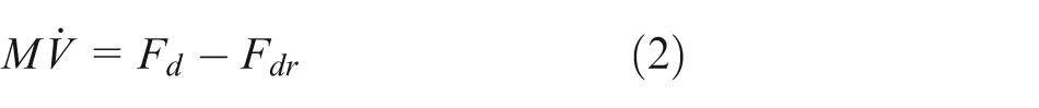
To ensure a safe two-dimensional operation of a four-wheel vehicle, its longitudinal motion control is the fundamental. As depicted in Figure 2, the dynamic differential equations for the longitudinal motion of the front-wheel drive EV can be described as


Longitudinal motion of the vehicle.
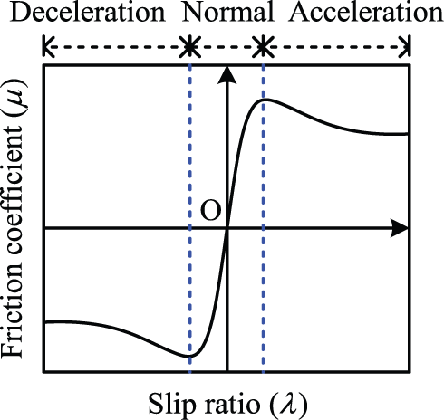
where the parameters’ definitions are listed in Table 1. Note that equation (1) stands for the wheel dynamics, equation (2) the vehicle dynamics, and equation (4) the tire tractive force. Basically, the nonlinear interrelationships between the slip ratio λ and friction coefficient µ formed by the tire’s dynamics can be modeled by the widely adopted magic formula 17 as shown in Figure 3. Figure 4 shows the deterioration of longitudinal and lateral frication force with different slip ratios. The slip ratio λ related to the wheel slip is defined as

Magic formula of tire.

Longitudinal and lateral friction force.
Parameter list.

where ε is a small positive constant adopted to ensure a nonzero denominator. Here from Figure 4, obviously, as the slip ratio increases, the quick loss on lateral friction force 18 will cause the vehicle to enter an uncontrollable scenario. To ensure a safe steering situation, the vehicle’s tractive force should be controlled in the effective traction zone as depicted in Figure 4. To maintain the tractive force in the vehicle, acceleration stage always falls on the traction control issues. Proper traction control prevents the tire-grip into a saturation scenario and avoids the happening of vehicle uncontrollable sliding.
To maintain a vehicle’s traction control, many approaches have been investigated. For example, approaches such as model following, 19 state estimator, 20 and traction force regulation 21 have shown the feasibility on practical tests. In this article, a new traction control oriented from our previous approach 8 will be presented in the following.
From equations (1) and (3), the traction force, that is, the friction force between the tire and the road surface, can be calculated as

Under normal operation, Fd is less than the maximum friction force from the road and increases as T goes up. However, when slip occurs, Fd cannot increase by T. Hence, when slip is occurring, the velocity difference between wheel and chassis become larger and larger, that is, the acceleration of the wheel is larger than that of the chassis. In order to prevent the phenomena which cause the vehicle sliding, a detection index is set as

is proposed to monitor the deterioration of traction force. This index plays an important role as a quality factor of the physical traction. For a normal driving condition without vehicle sliding, ς ≈1. As can be seen in Figure 3, if the slip ratio λ increases, |ς| ≥ 1. Note that, in order to avoid zero denominator, for special case of Vw = 0 (i.e. the vehicle is fully stopped), one assumes ς = 1. Substituting equations (1)–(3) into (7), one can obtain
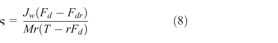
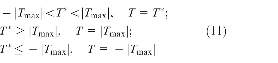
Basically, from the magic formula, one knows the tire traction force will reach a maximum value for a stable steering. Over the maximum value, the traction force will be saturated and the stability drops quickly. Consequently, the wheel motor has a maximum value of transmissible torque T max for each driving. Herein, rearranging equation (8) and assume T = T max and the friction force Fd is estimable for a perfect driving condition. One can have T max as

Note that the maximum traction limitation is always on the starting stage. Hence, the Fdr should be at least 2–6 times less than Fd for propulsion. Otherwise, the propelling force will become unsmooth. Consequently, equation (9) can be simplified as equation (10)

The driving resistance Fdr
is treated as a dynamic perturbation source of the vehicle mass M.
7
Additionally, the driving force estimation
EDS and ESC for two-dimensional driving
ESC
In order to guarantee a safe steering, the two-dimensional vehicle dynamics reveals more sophisticated problem in the dynamic motion stabilization. Generally, the stabilization of longitudinal and lateral motion and yaw moment about the vertical axis are curial issues. Consequently, the handling of the vehicle is in line with the driver’s steering volition and with the corresponding road conditions. In order to describe the vehicle’s two-dimensional behaviors, a two-wheel vehicle model, namely, the single-track model or bicycle model, is introduced herein. The essential assumption is the combination of the two tires of an axle into one substitutive tire in the vehicle center plane, consequently neglecting the height of the center of gravity (CG) of the vehicle above the road surface. Usually, this two-wheel model of a passenger car is linearized by considering small angles only and a linear description for the steady-state lateral tire forces. In addition, most cases assume that the chassis velocity V is constant, and the longitudinal tire forces are neglected with respect to their influence on the lateral dynamics. Ordinarily, the aerodynamic resistances are neglected as well as the aforementioned equations.
As shown in Figure 5, the governing equations of lateral and yaw motions can be expressed as follows 22
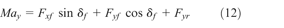
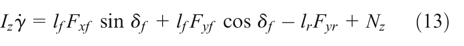

Linear two-wheel vehicle model for lateral dynamics.
where ay
denotes the vehicle lateral acceleration, M stands for the nominal vehicle mass, Iz
represents the moment of inertia for the z-axis, γ is the yaw rate, and δf
is the steering angle of the front wheel. lf
and lr
are the distances from the CG to the front and the rear axle, respectively. Fxf
is the longitudinal friction force of the front tires, and Fyf
or Fyr
are the lateral friction force of the front and rear tires, respectively. From the centripetal kinematics, one can have

where d is the rear track width. Note that the compensation torque Nz is applied to compensate the unnecessary rational torque caused by two-dimensional vehicle sliding. Consequently, this compensation torque can be carried out by braking and/or driving torque. If a vehicle equips both the ABS and TCS for anti-slip control in longitudinal motion, the compensation torque Nz for avoiding the two-dimensional slide can then be achieved by the collaboration of these two techniques. Under the scope of the bicycle model, the magnitude of Fylf and Fyrf is the set as Fylf + Fyrf = Fyf and Fylr + Fyrr = Fyr , respectively. In the analysis, the toe-out on turns is assumed to be omitted. Consequently, the tire-slip angles of front-left and front-right are set the same. Thus, the lateral force Fyf and Fyr can be found as


where Cf
and Cr
are, respectively, the equivalent front and rear cornering stiffness, and θf
and θr
are the tire sideslip angles of the front and rear wheels, respectively. Note that θf
is the angle between vehicle speed and front wheel speed and θr
is the angle between vehicle speed and rear-wheel speed, respectively. Generally, θf
> θr
. If the front and rear tires are the same, then Cf
= Cr
. The relationship between wheel steering angle δf
, chassis velocity V, and yaw rate γ during steady-state driving on a circular course is taken as the basis for the desired vehicle motion during steady-state driving, and when braking and/or accelerating. Under the two-wheel model, the nominal yaw rate

where

Under a normal steering, this nominal yaw rate is limited to the friction coefficient µ as
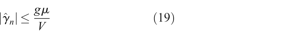
where g is the gravitational acceleration constant. Basically, it is difficult and inefficient to influence the vehicle’s lateral velocity directly. However, it is reasonable and effective to make use of the advantages of independent in-wheel motors to control the lateral motion indirectly regulate the vehicle’s sideslip angle. The rotation of the vehicle is initiated by the generation of yaw moments, which can be adjusted by controlling the difference of longitudinal driving torques between the left and the right wheels. This is the basic concept of DYC. Note that herein the electronic differential steering is assumed to cope well.
EDS
Another issue for in-wheel motor EV is EDS. The EDS is utilized for a smooth turning with less tire scrubbing. Since the vehicle is propelled by independent in-wheel motors, the electronic differential steering algorithm aims to distribute the torque command to the left and right wheels for the required vehicle motion, and orientation control is important for this. In this article, the electronic differential algorithm is directly applied from our previous work 4 as
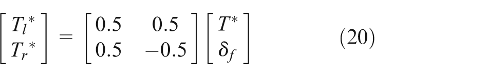
where T
* is the driving pedal command,
Proposed motion stabilization
In this section, an integrated motion stabilization approach based on the yaw-moment control for decentralized EVs will be proposed. Conventional DYC system has no traction control embedded to guarantee the sufficient driving torques. 23 Therefore, the difference of driving torques between the left and the right wheel cannot ensure appropriate yaw moment as requested. Moreover, an unexpected slip between the wheel and the road surface can be induced by the increased driving torque, which will decrease the lateral friction force and deteriorate the vehicle stability. Figure 6 illustrates the proposed motion stabilization methodology. As can be seen in this figure, the EDS is setup before the traction distribution and traction control. The traction distribution unit plays a role as the ESC. It deals with the yaw rate control to achieve a neutral-steering under a two-dimensional vehicle operation. This approach did not directly regulate the sideslip angle. However, the sideslip angle can be suppressed to a small value if the steering stability (i.e. yaw rate) is under control. The detailed mechanism and control scheme are shown in Figure 7. Traction control unit directly applies the algorithm synthesized from equations (10) and (11). The traction control works well on a single wheel traction. Clearly, the tire’s lateral traction force can be quarantined under a good foundation of longitudinal traction force. Hence, when the vehicle is steered under a two-dimensional motion, the lateral traction is important. In addition, the single wheel traction is the basis of a two-dimensional motion. Under the guarantees of best traction on each propulsion wheel, the ESC, which is based on DYC, can be adjusted and compensated quickly. With less sliding of each traction wheel, the vehicle can be maintained under a neutral-steering, which satisfies the driver’s consciousness sharply.
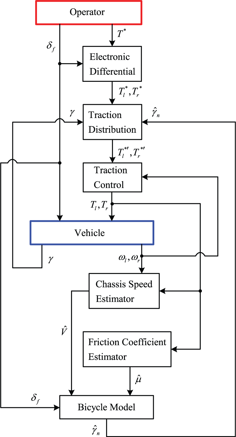
The proposed motion stabilization methodology.

Traction distribution mechanism.
Experimental EV
For the sake of implementing and evaluating the proposed control system, a hands-on EV, namely Corsa-EV, as shown in Figure 8, was proposed to carry out the experiments. This prototype modifies from the gasoline engine car: Opel Corsa. In this prototype, each front wheel is equipped with a Permanent Magnet Synchronous Motor (PMSM) and can be controlled independently. The system is powered by the lithium ion battery pack as shown in Figure 9. In this study, the experimental data are collected via the data acquisition card as Figure 10. Table 2 summarizes the main specifications. In the presented system, a 16-bit microcontroller (Microchip dsPIC30F4011) is employed to take the place as the electronic control unit (ECU) to operate the motion control. The microprocessor receives signals from sensors and synthesizes corresponding driving command to each motor driver. In addition, the corresponding performances are recorded for individual inspection and evaluation. Figure 11 illustrates the schematics of Corsa-EV electrical system.

Prototype vehicle: Corsa-EV.

Lithium ion battery pack.

NI9401 data acquisition card.
Main specifications.

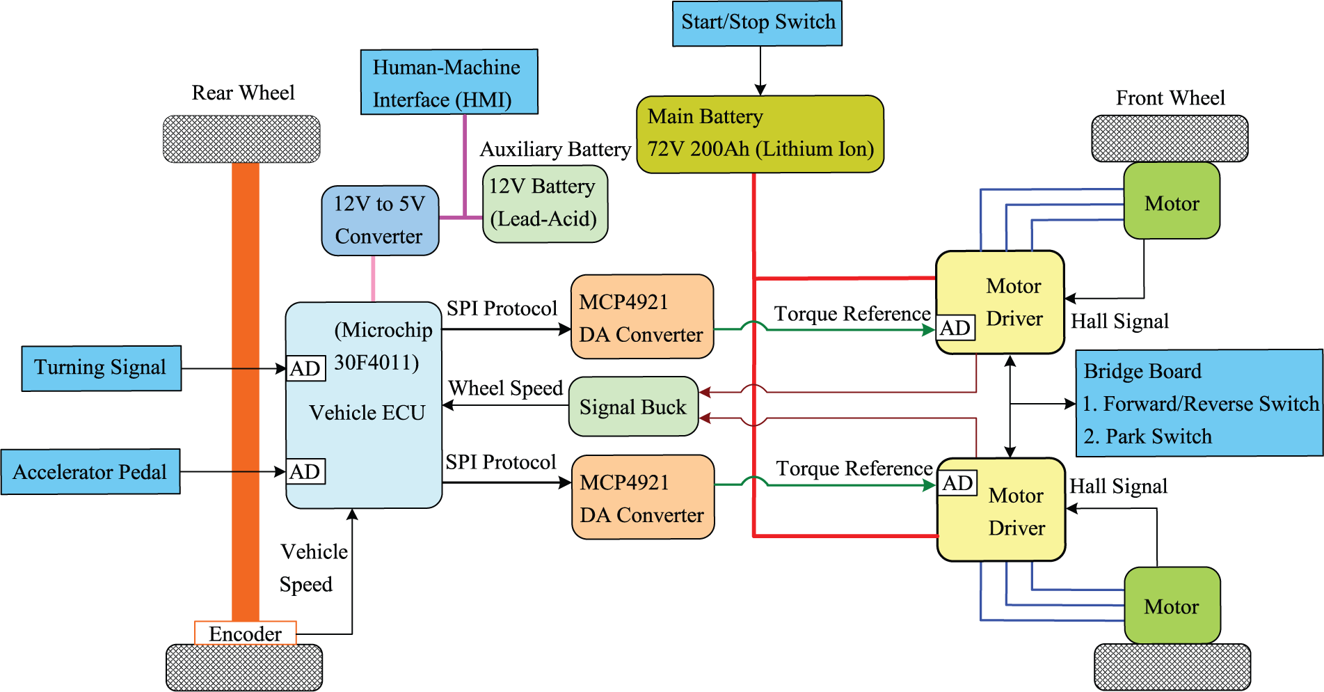
The schematics of Corsa-EV electrical system.
Examples and discussions
In this section, the proposed motion stabilization will be evaluated in a series of experiments. All the experiments are carried out practically on Corsa-EV. As shown in Figure 11, in order to measure the vehicle velocity, one rear wheel (right wheel) without propelled motor torque (i.e. passive wheel) is equipped an encoder to measure the vehicle speed. This encoder is refit from an ABS speed sensor and has the specifications as shown in Table 2. The wheel speed is measured and synthesized from the hall sensor signal on the motor drive. Note that δf represents the turning signal and T * is coming from the accelerator pedal.
Traction control
The first experiment is the evaluation of TCS. Traction control plays a role to suppress the wheel skidding in a longitudinal vehicle stating. First, Figure 12 shows the experimental results without traction control. In this test, the front and rear left wheels will enter a sliding plate from 18.5 to 21.5 s. The sliding plate is made by smooth plastics and its surface is lubricated with engine oil. The front and rear right wheels are always staying on the blacktop. As can be seen in Figure 12(a), due to the tire sliding, the velocity difference between wheel and vehicle becomes larger. Figure 12(b) shows the corresponding quality factor of ς. Figure 12(c) illustrates the comparison of pedal command and motor command T. Obviously, under proper control, the skidding phenomena can be cured. Figure 13 shows the performance under the proposed traction control of equation (11). As can be seen in Figure 13(a), the velocity difference between wheel and vehicle is constrained into an acceptable range under the traction control activated. The maximum transmissible torque can be obtained by taking the parameters of Table 2 and the estimated friction force into equations (8) and (10). After having the maximum transmissible torque of equation (10), the traction control strategy of equation (11) then can be carried out. Figure 13(c) illustrates that the motor command T is suppressed into a lower value due to the traction quality factor of ς (as shown in Figure 13(b)) rises when the vehicle entering to the slippery area. Apparently, from the practical evaluation, the presented traction control improves the dynamic stability in a longitudinal motion.
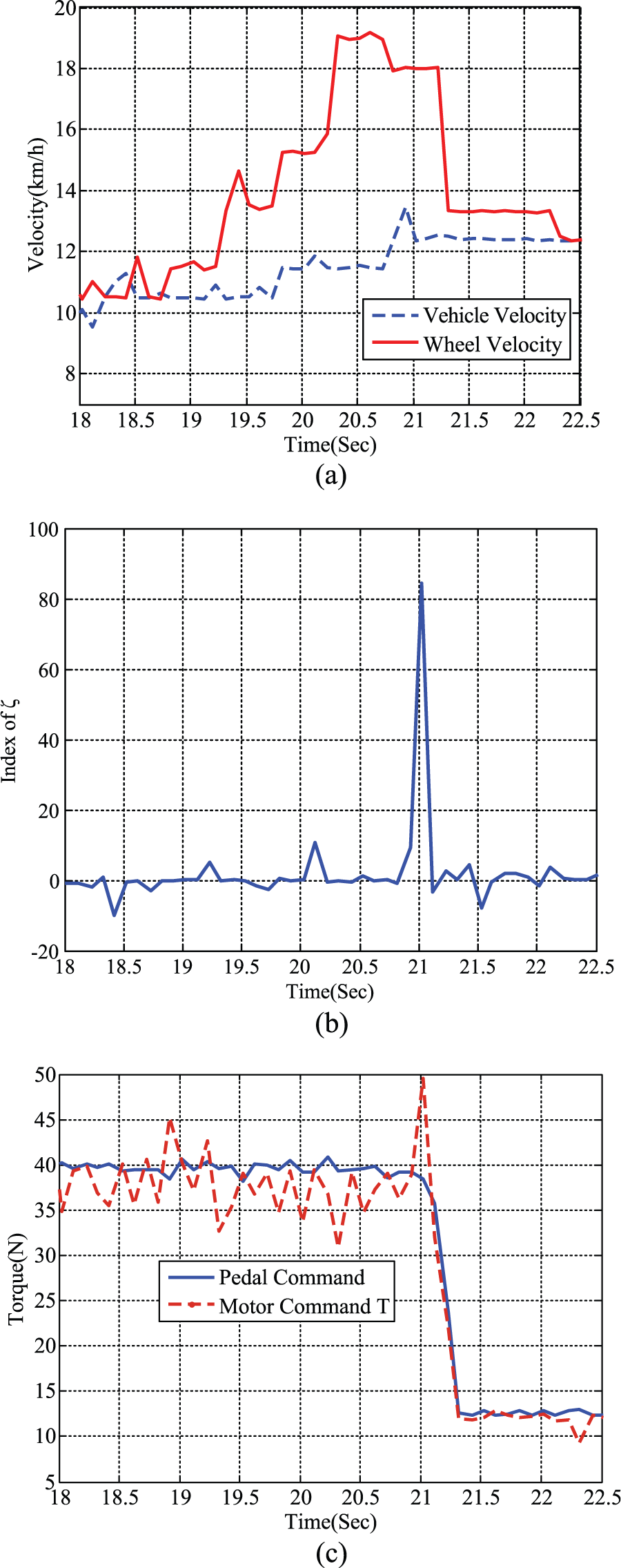
Experimental results without traction control: (a) the velocity difference between wheel and vehicle, (b) the real time index of ς, and (c) comparison of pedal command and motor command T.

Experimental results with proposed traction control: (a) the velocity difference between wheel and vehicle, (b) the real time index of ς, and (c) comparison of pedal command and motor command T.
Electronic differential
To have a safe driving experience, not only the linear motion but also two-dimensional steering is concerned. In the following, the dynamic stability will be evaluated into two tests. First is the electronic differential. As mentioned, electronic differential plays a role to negotiate the command distribution for a smooth turning. Under proper torque control, the power decentralized EV can turn smoothly with less tire scrubbing and sliding. Based on the algorithm of equation (20), Figure 14 reveals a comparison results between the front-left and front-right wheels. This is a turn left test. As can be seen in this figure, in order to have a nimble response, the right wheel speed will be higher than left wheel. The EDS not only makes the two-directional steering safer but also saves more energy due to the tire protection.

Comparison of experimental results of left and right wheel velocity.
ESC
Proceeding forward, the performance evaluation of the whole presented system, that is, Figure 6, will be revealed. As mentioned above, the proposed approach for power decentralized EV is constructed under the foundation contributed from TCS and EDS. The presented motion stabilization control for vehicles’ two-dimensional motion is then carried out by controlling the yaw moment to acts the role as ESC. As can be seen in Figure 7, the yaw rate control distributes the driving commands. In practical test, a proportional integral (PI) controller is utilized in the experiment. Herein, the PI control gains should be adjusted based on the required bandwidth of yaw rate tracking. Under an acceptable controller gains, the traction distribution can build a decentralized traction torque pair for propulsions. Then, this traction torque pair will be put into the traction control mechanism for the tire-slip prevention. Figure 15 illustrates the experimental scenario of performance test. The testing vehicle is continuously driving in a clockwise circle. Additionally, a sliding plate is placed inside the driving path. Figure 16 shows the experimental results when the testing vehicle is entering the sliding plate. As can be seen in Figure 16(a), the yaw rate changes sharply due to the wheel skidding. During the skidding zone, the operator adjusts the steering wheel to correct the moving path back into the circle. Base on the scheme of Figure 7, as can be seen in Figure 16(a), the comparison results show that the estimated yaw rate quickly follows the actual yaw rate. During the series operation adjustment, Figure 16(b) illustrates the comparison of commands between pedal, left wheel, and right wheel, respectively. As can be seen in this experiment, the control system utilizes the benefits of independently controlled motor to accomplish the complicated motion stabilization in real time. Herein, from the evaluating examples, the proposed dynamic motion stabilization reveals feasible and reliable performance in a series of practical tests.

The experimental scenario of proposed test.
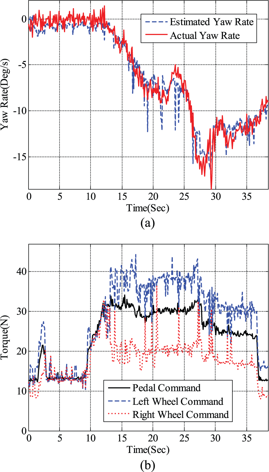
The experimental results of proposed yaw-moment control: (a) experimental results of yaw rate control and (b) comparison of pedal command and left and right wheel command.
Conclusion
This article has presented an integrated solution for dynamic motion stabilization control on front-wheel drive in-wheel motor EVs. The proposed approach has covering the functions such as traction control, electronic differential, and ESC. The presented approach has been confirmed with its performance in both practical linear and two-dimensional experiments. It has been verified that the proposed control system has benefits such as preventing possible failures in a slippery driving situation no mater longitudinal or turning situations. The experimental results have substantiated that the proposed strategy has the ability, in practice, to improve the EV’s dynamic motion stability. Consequently, under the guarding of proposed system, the driving experience and safety can be further enhanced.
Footnotes
Academic Editor: Teen-Hang Meen
Declaration of conflicting interests
The author(s) declared no potential conflicts of interest with respect to the research, authorship, and/or publication of this article.
Funding
The author(s) disclosed receipt of the following financial support for the research, authorship, and/or publication of this article: This work was supported by the Ministry of Science and Technology (MOST) of Taiwan, under projects MOST 101-2221-E-024-011 and 104-2115-M-142-001.