
Abstract
This study intends to fabricate a small-size capacitive wireless transmission device. As to the design of electrode plates, the active electrode is designed in two ways, through row array and column array, and the area of an electrode plate is limited to below 20.25 cm2. Moreover, the passive electrode of row-array electrode plates is designed in three ways: general row array, window array, and rhombus array. As seen from the results of circuit simulation, the transmission efficiency of the capacitive wireless transmission device is as high as 0.7. In the actual circuit experiment, the electrode plate in the window-array design has the highest efficiency at 51%. In addition, the electrode plates in the window array and those in other arrays have higher stability and transmission efficiency. In the rotational angle dislocation experiment, the unit area current amount of the column-array electrode plates in the high coupling region is also smaller than that of the window-array electrode plates. However, the performance of column-array electrode plates reaches higher stability in the angle dislocation experiment, and its anti-angle dislocation is obviously higher than that of the electrode plates designed in the other three row arrays. Moreover, when the area of the column-array electrode plates is 22.25 cm2, the highest transmission distance is 22.5 mm.
Keywords
Introduction
In recent years, wireless power transfer (WPT) has been gradually receiving greater attention and has started to be applied in daily life. 1 WPT is a kind of charging technique that breaks away from the traditional cable joint approach. This kind of technique can be performed in different ways, including electromagnetic induction, inductive coupled power transfer (ICPT), capacitive power transfer (CPT), and microwave. Basically, all these techniques use the resonance frequency of the voltage on the charging end to transmit energy to the charged end. As shown in current studies, ICPT is the most extensively applied method since its transmission distance can reach up to eight times that of the induction coil.2,3 This technique was first proposed by Nikola Tesla in 1919. However, at that time, electronic circuits were not as advanced and well-developed as today, making it difficult to realize WPT. Today, WPT has become more mature, and CPT has been well-developed for application to signals.4–8 In the aspect of charging, although CPT is not as good as ICPT when it comes to the energy transmission distance, its transmission efficiency during short-distance charging is as high as 95%, thus enjoying a great advantage. As for wireless charging of portable electronic devices, it is assumed these devices are placed on a charging stand. However, this kind of close-distance charging must take into account anti-dislocation and efficiency. CPT is hence most suitable for portable electronic devices due to its small size, enabling it to be attached to portable devices. In times of ICPT charging, if there is a foreign metallic object in the charging zone, its efficiency is obviously reduced, and the portable device itself becomes hot and unsafe. CPT, on the other hand, can penetrate foreign metallic objects to conduct charging. During energy transmission, since the electromagnetic field is restricted between two electrode plates, electromagnetic interference is low and safety is enhanced. The competitiveness of this kind of placed-on WPT is not inferior to electromagnetic charging.
As shown by previous works, CPT has been applied to the manufacturing process of complementary metal–oxide–semiconductor (CMOS) chips. When it is applied to signal transmission chips, the power loss of chips can be effectively reduced. 9 Furthermore, this technique has also been suggested for application to biological medicine by taking human skin as a dielectric for simulation and for comparison with electromagnetic resonance techniques. 5 Charged electrode plates can also meet the needs of rotatable structure design and be combined with the CPT technique to replace the electric brushes of motors.10,11 In recent years, in order to solve the short circuit problem brought about by dislocation of the electrode plate in the CPT technique, a radiofrequency (RF) antenna and control circuit were added to the circuit to turn the electrode plate on and off, thus enhancing the unit area charging efficiency up to 2.55 × 10³. 12 As for the design of electrode plates, a new kind of column-array electrode plate has been proposed, using structural difference to resolve the short circuit problem caused by dislocation. 13
Nevertheless, according to the studies, the size of both the active and passive electrodes was mostly over 10 × 10 cm2, making it impossible to embed the plates in small-size electrical devices. Moreover, the circuits of these plates also used more electronic components. Therefore, this study attempts to fabricate a CPT charging system with simple electronic component circuits and tremendously decreased size. In addition, comparison and discussion are carried out after stability experiments using electrode plates with different charging systems.
Experimental details
The main concerns in active end circuit design include the oscillation circuit and transistor switch. Since electric field coupling under higher frequency operating voltage acquires better coupling efficiency, circuit design takes high-frequency oscillation as its main concern. Moreover, the transistor switch has to be attached to a transistor with high frequency in order to acquire a stable output waveform. Furthermore, the oscillation circuit has to be equipped with tuning inductance to match with the circuit so as to greatly improve the conversion efficiency. As to the circuit design in the passive end, it has to be equipped with tuning inductance to match with the circuit, as well as a filter capacitor to filter out bad signals. Through tuning inductance and filtering, its efficiency can be improved. Since the circuit design proposed here involves the design of a high-frequency circuit, a high-speed diode rectifier is used, and its reaction rate can reach 4 ns maximum. After it is connected with a rectifier capacitance, a stable DC voltage output can be obtained.
First, a circuit simulation software Multisim is used to design the circuit and measure the various parameters. Voltage is set at 30 V. A frequency generator is used to generate the oscillation frequency, which is set at 1.35 MHz. From the software’s built-in measuring and calculating functions, it is known that the capacitance at the sending end is Cs, the capacitance at the receiving end is Cp, and the mutual capacitance in times of coupling is Cm. The simulated transmission efficiency η, coupling constant kg, and charge efficiency G can then be acquired. 14 After exploration of its feasibility, electronic components are used to assemble the designed circuit. A photosensitive circuit board is also used. After it has gone through exposure, development, and etching processes, the active ends of row-array electrodes are fabricated. Copper foil and a poly(vinyl chloride) (PVC) sheet are used to fabricate the electrode plates of three different passive ends, as well as the active end and passive end electrodes of column-array electrode plates. Figure 1(a) shows a schematic diagram of row-array active end electrode plates. They are made of photosensitive circuit boards. Same-color blocks are stagger-arrayed like a chessboard to form a parallel guide board. Figure 1(b) shows the passive electrode plates, among row-array electrode plates, in three different array ways. From left to right, they are in a general row array, window array, and rhombus array. Since it is assumed that the system shall be embedded in small-size electrical devices, each small electrode guide board is designed with an area 2 × 2 cm2, and the distance between boards is set at 0.5 cm. Figure 2(a) shows the schematic diagram of the active end electrode of column-array electrode plates. They are made of a Cu sheet and 0.05 mm PVC sheet, with an area of 10 × 15 cm2. Figure 2(b) shows the passive electrode end of the column-array electrode plates, in stack structure, with an area of 2 × 2 cm2. After fabrication is completed, an oscilloscope and multi-meter are used to measure and record the voltage waves produced after joining the active end and passive end electrode plates in different arrays and to calculate their coupling constant, transmission efficiency, and unit area current amounts. Moreover, focusing on the passive electrode plates in different arrays, this study observes the correlation between array types and anti-dislocation in the displacement experiment conducted in the charging zone. In order to determine the stability of different electrodes toward displacement and dislocation during charging, this article analyzes the dislocation of row-array and column-array electrode plates outside the charging zone and compares the analytical results.

Schematic diagram of row-array electrodes: (a) active end electrodes and (b) passive end electrodes in three arrays.

Schematic diagram of column-array electrodes: (a) active end electrodes and (b) passive end electrodes.
Experiments are designed particularly for low coupling, which may happen due to displacement and dislocation. These experiments include an angle displacement experiment in the charging zone, a vertical displacement experiment, and experiments outside the charging zone. The structural difference between row-array electrodes and column-array electrodes makes the former produce a low coupling zone in the charging zone. We put these three different passive electrode plates in the high coupling zone to conduct XY direction displacement. After each displacement of 5 mm, the current amount is recorded, and the unit area current produced by the electrode plate is calculated. This article discusses the correlation between the array type of the row-array electrodes and stability in the anti-charging zone. Column-array electrode plates with an equivalent area of active end and passive end electrodes are added in the Z-direction rotation experiment. After each rotation of 10°, data are recorded. This study also calculates and discusses the resistance of row-array electrodes and column-array electrodes during rotational dislocation. In the dislocation experiment outside the charging zone, an experimental comparison is made between two electrodes with similar conditions among the row-array and column-array electrodes. A record is kept after each displacement of 5 mm. In the vertical displacement experiment, experimental results of row-array electrodes and column-array electrodes with three different arrays are compared to measure the highest transmission distances achieved under different electrode plates. Moreover, for the column-array electrode plates with different areas, 2.5 × 2.5 cm2, 3 × 3 cm2, 4 × 4 cm2, and 4.5 × 4.5 cm2, we conduct a vertical displacement experiment with the passive electrodes. After each displacement of 2.5 mm, we record and explore the correlation between the area of electrode guide board and the highest transmission distance.
The circuit design of this study is different from that of past studies of control circuits and oscillation circuit. A flip-flop is used to match with an npn transistor in order to decrease the entire circuit volume, and the production cost is also obviously reduced. Moreover, input voltage reaches high-frequency oscillation under the condition that there is almost no loss of voltage. The oscillation frequency can reach nearly 1.2 MHz, which is close to the open frequency at 1.35 MHz. As to the making of the electrode plate, both the active end and passive end adopt staggered and side-by-side design. The area of the passive electrode plate is even smaller than that in previous works and limited within 20.25 cm2. Therefore, with this advantage, the system can be embedded in small-size appliances, such as mobile devices.
Results and discussion
Figure 3 shows a simulated circuit diagram. A is the active end, which contains a frequency generator and npn transistor serving as an electronic oscillator switch. B is the passive end, which is composed of a diode rectifier as well as a capacitor and load rectifier. Table 1 shows the various parameters in the circuit diagram. In the circuit simulation results, it is known from the active end that the designed electronic switch can receive a 1.35-MHz signal and function to make the DC voltage source oscillate. In the simulation, after active and passive electrode plates are perfectly joined, an AC voltage with a wave crest of 11 V, trough of wave of −16 V, and frequency of 1.32 MHz is produced. As for calculations of efficiency, the coupling constant is 0.7 and the transmission efficiency is as high as 70%, showing the high feasibility of the circuit system.
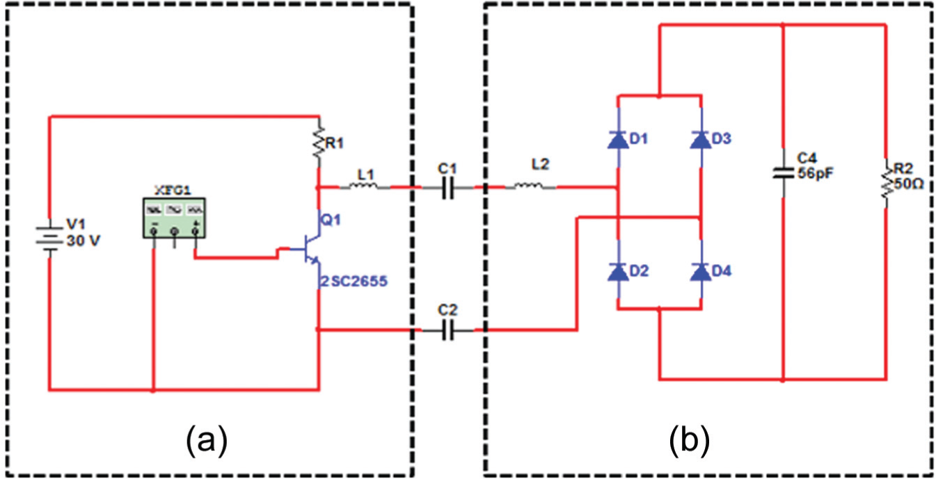
Simulated circuit diagram of the CPT system.
Various parameters in the circuit diagram shown in Figure 3.

Row-array and column-array electrode plates in three arrays are assembled into real circuits as shown in Figures 4 and 5. A real circuit is different from simulated circuit. On the oscillation current, a flip-flop is used as the source of the oscillation signal, and IC-7812 is used as the component controlling the voltage source of the flip-flop. The oscillation current of the flip-flop sends out an oscillation frequency of 1.67 MHz, as shown in Figure 6. After the active end and passive end function on electric field, an AC voltage wave with a frequency of 1.2 MHz and wave crest 14v is produced, as shown in Figure 7. We measure the electrode plate current Iss on the active side, the electrode plate current Ipp on the secondary side, and the lowest contact area A between the active end and passive end electrode plates. We then calculate the coupling constant kg, highest transmission efficiency ηH, and lowest transmission efficiency ηL in the charging zone, as well as the highest output power P, highest charging efficiency G, and unit area transmission efficiency δ. Various parameters are shown in Table 2. As observed from Table 2, column-array electrode plates exhibit the most remarkable performance in unit area transmission efficiency δ, at 0.037, which is much higher than the value of 0.0211 in the row-array electrode plates. Although the row-array electrode plates of the window parallel array reach transmission efficiency η up to 51%, the unit area transmission efficiency δ is only around 0.004 higher than the other two kinds. As to unit area charging efficiency, window-array plates are the highest at 5.7610 ×10⁻⁴. Moreover, we also found that in the tables with row-array electrode plates, no matter under a window array or a rhombus array, a low coupling zone occurs in the charging zone due to geometric structure. The greatest difference in transmission efficiency between the high coupling zone and low coupling zone is as high as 46%. On the other hand, although the transmission efficiency of the column-array electrodes during the highest coupling is not as good as that of row-array electrodes, these electrodes do not exhibit a low coupling zone in the charging zone.

Real pictures of row-array electrodes: (a) active end and (b) passive end.

Real pictures of column-array electrodes: (a) active end and (b) passive end.
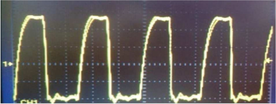
Oscillation signals sent out from flip-flop.
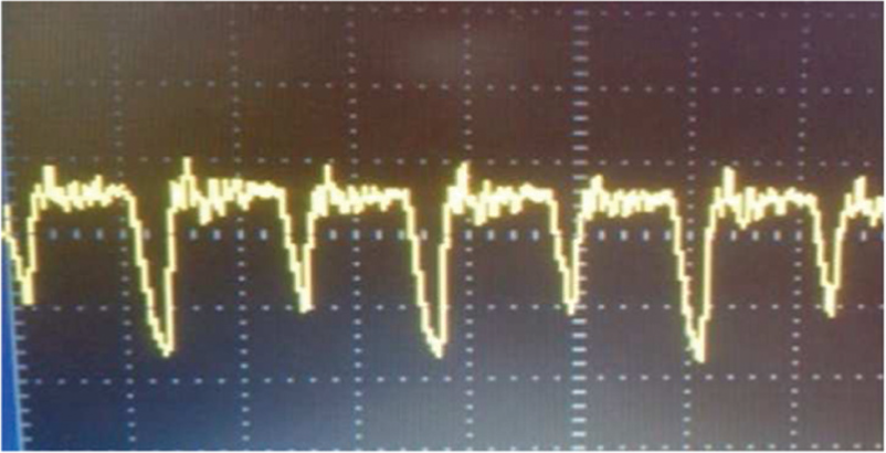
Voltage waves produced after functioning of active and passive electrode plates.
Parameters of different electrode plates in the CPT system.
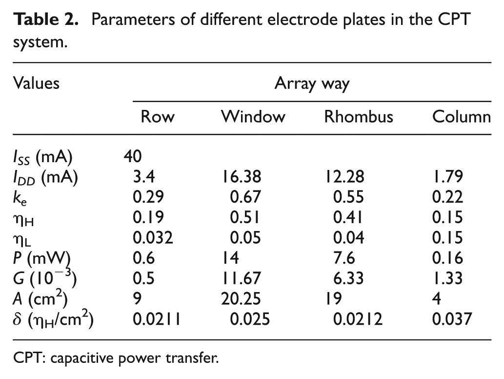
CPT: capacitive power transfer.
Figures 8 and 9, respectively, show the unit area currents acquired after X-direction displacement and Y-direction displacement of row-array electrodes in the charging zone. In these figures, a represents general row array, b represents window parallel array, and c represents rhombus parallel array. As observed from these figures, low coupling zones occur for all three kinds of row-array electrodes when XY direction displacement is made from 10 to 15 mm and 35 to 40 mm. These three different kinds of row-array electrode plates show high to low unit area current amounts in the high coupling zone shown: window parallel array > rhombus parallel array > general row array. Moreover, in Y-direction displacement, the window parallel array achieves the most remarkable performance in both the high coupling zone and low coupling zone.

Correlation between X-direction displacement of row-array electrodes and unit area current.
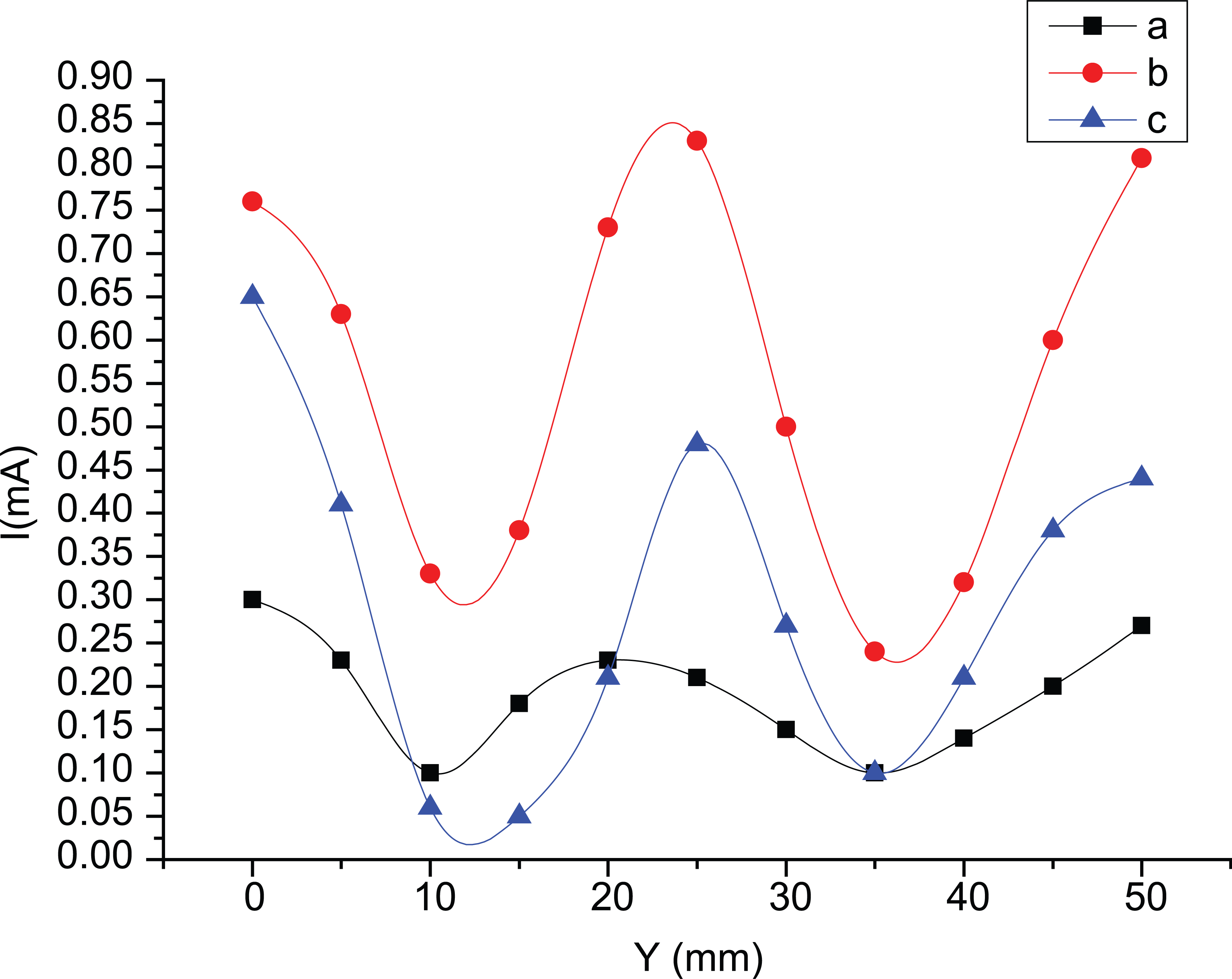
Correlation between Y-direction displacement of row-array electrodes and unit area current.
In the angle dislocation experiment, we add column-array electrode plates to compare row-array electrode plates in three different arrays, as shown in Figure 10. In this figure, a represents general row array, b represents window parallel array, c represents rhombus parallel array, and d represents column-array electrodes. Among these three kinds of row arrays, the efficiency of general row array and window array obviously decreased at rotational angles 45° and 135°, while their efficiency increased with higher currents only at rotational angles 0° and 150°–180°. Moreover, it is also found that the column array appears to achieve higher stability in angle dislocation. The anti-angle dislocation of this type of array is obviously higher than that of the three kinds of row array.
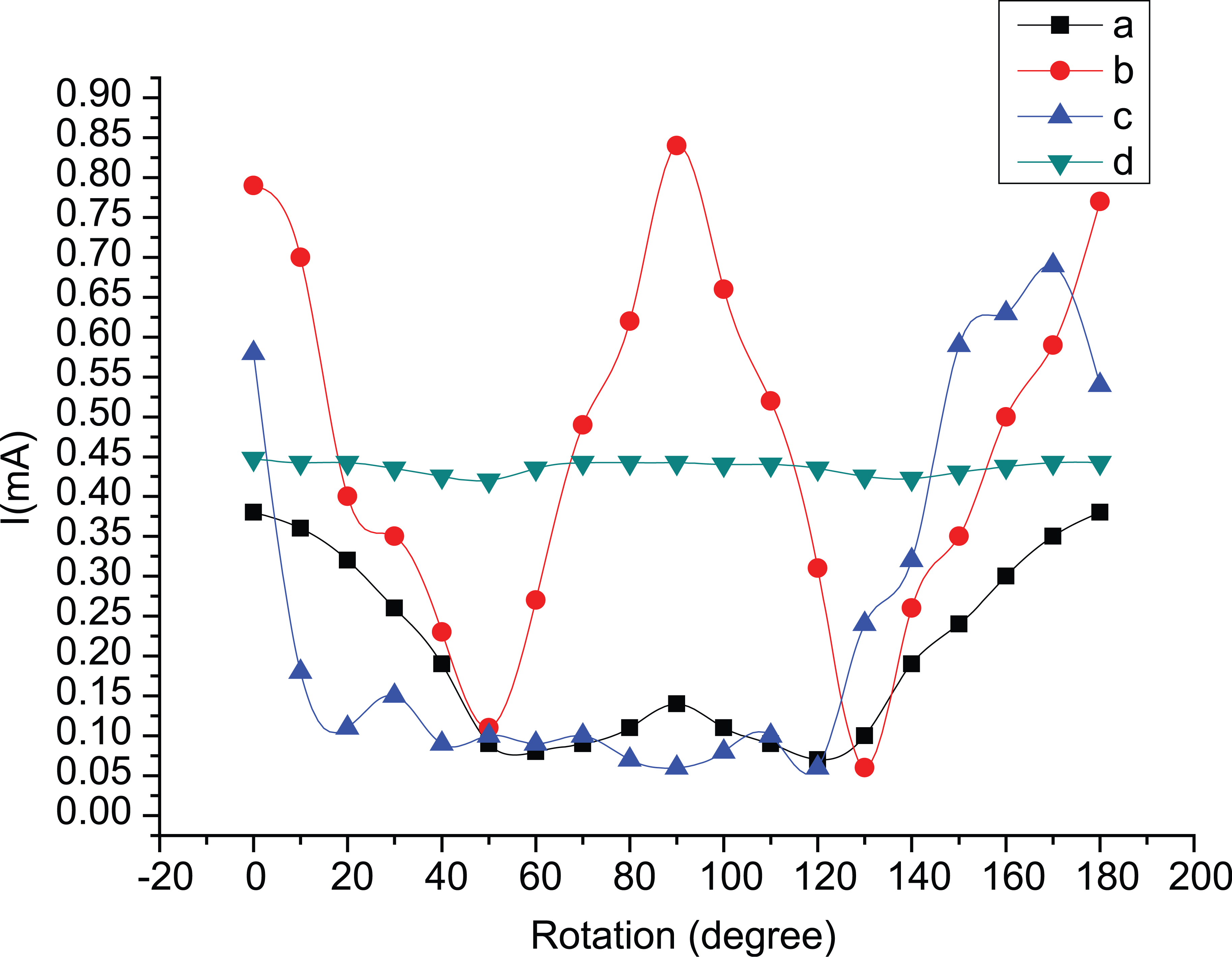
Correlation between rotational angle and unit area current of four different kinds of electrode plates during Z-direction rotational dislocation.
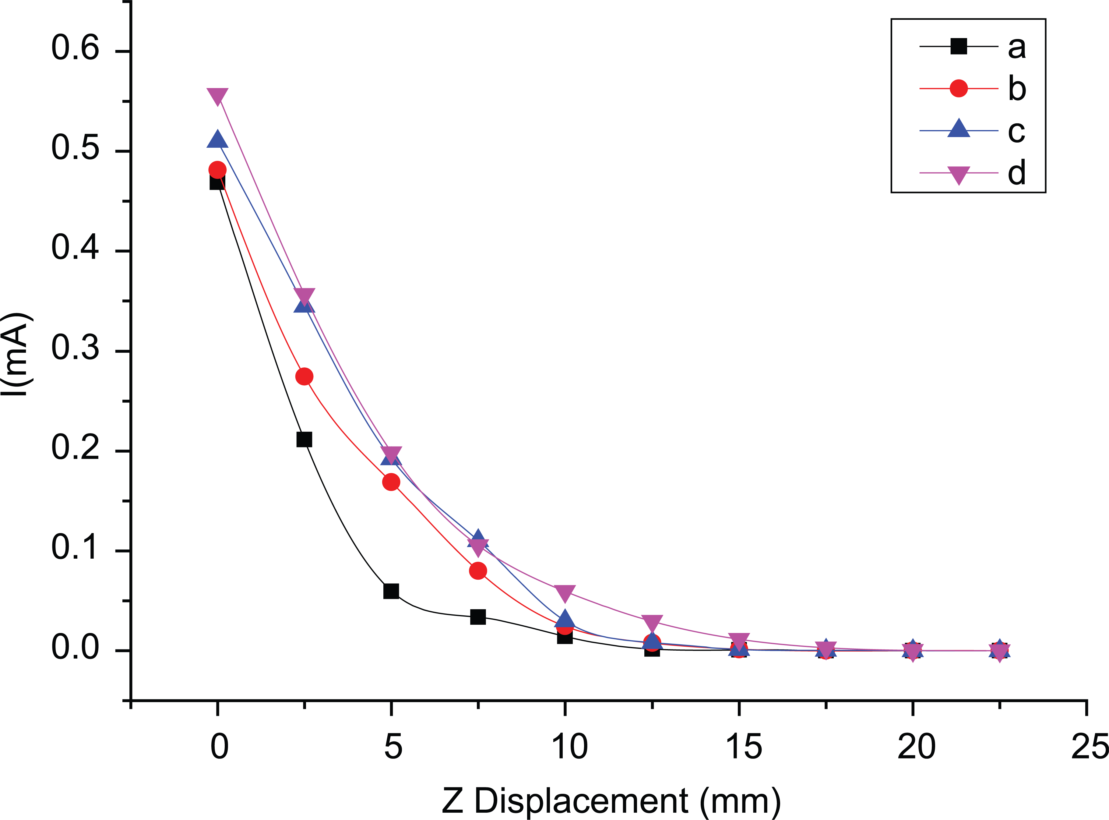
The experimental results of three kinds of row-array and column-array electrode plates in Z-direction vertical displacement experiments are shown in Figure 11. In the figure, a represents general row array, b represents window parallel array, c represents rhombus parallel array, and d represents column-array electrodes. As found in this figure, the three array types have greater effects on the factors of height and distance. When height is increased to above 5 mm, it is found that the unit area current of the column array is obviously lower than that of the three kinds of row-array electrode plates. The greatest transmission distance is 15 mm. Moreover, among the row-array electrodes, the window-array ones have greater unit area current amounts than do general array electrode plates.

Correlation between height and unit area current during Z-direction vertical displacement of four different electrode plates.
In the XY direction dislocation experiment conducted outside the charging zone, column-array electrodes with the same area are compared with general row-array electrodes, as shown in Figures 12 and 13. In these figures, a represents general row array and b represents column-array electrodes. As observed from Figure 12, due to geometric reasons during X-direction dislocation, when two electrode plates are dislocated 17.5 mm, the unit area current amount of the row-array electrodes is higher than that of column-array electrodes. However, after comprehensive viewing of these two graphs, it is known that the anti-dislocation of column-array electrodes is higher than that of the general row-array electrodes.

Correlation between distance and unit area current of row-array and column-array electrode plates during X-direction dislocation.
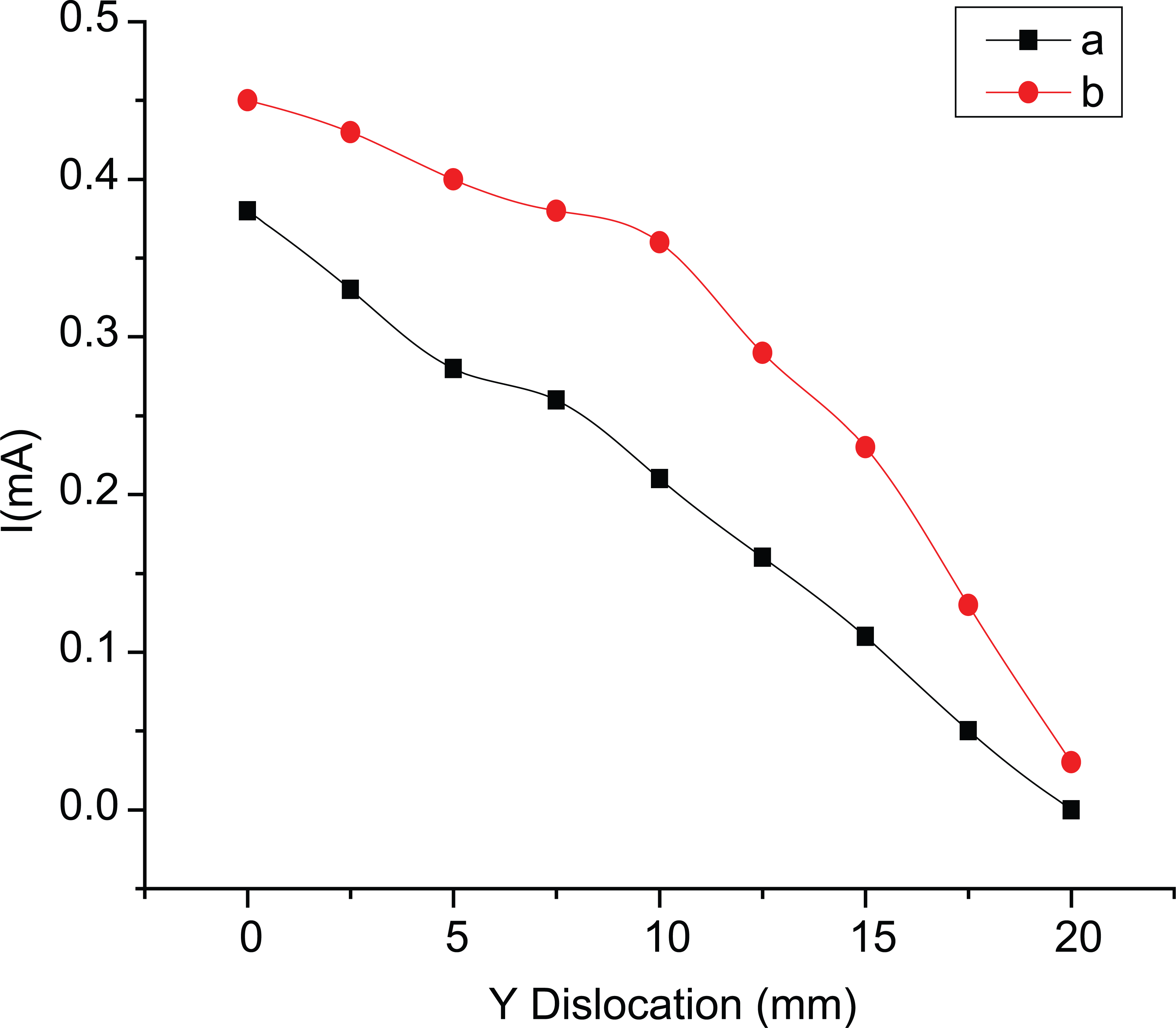
Correlation between distance and unit area current of row-array and column-array electrode plates during Y-direction dislocation.
The unit area current amounts of column-array electrode plates of different areas obtained at different transmission distances are shown in Figure 14. In the figure, a is 6.25 cm2, b is 9 cm2, c is 16 cm2, and d is 20.25 cm2. As known from the figure, when the area of column-array electrode plate is greater, not only is its unit area current amount increased, the transmission distance also increases accordingly.
Unit area current amounts of column-array electrode plates of different areas obtained at different transmission distances.
Conclusion
This study fabricates a small-size capacitive wireless transmission device. In the design of the electrode plate, an active electrode is designed in two ways, using row array and column array, and the passive electrode of the row-array electrode plates is designed in three ways, using general row array, window array, and rhombus array. Experimental results show that the electrode plate in the window-array design has the highest efficiency at 51%. In addition, the electrode plates in the window array and those in the other arrays have higher stability and transmission efficiency. Furthermore, the unit area current amount of the column-array electrode plates in high coupling region is smaller than that of window-array electrode plates, according to the experimental results of rotational angle dislocation
Footnotes
Academic Editor: Stephen D Prior
Declaration of conflicting interests
The author(s) declared no potential conflicts of interest with respect to the research, authorship, and/or publication of this article.
Funding
The author(s) disclosed receipt of the following financial support for the research, authorship, and/or publication of this article: The authors would like to thank the National Science Council of the Republic of China, Taiwan, for financially supporting this research under Contract No. NSC 102-2221-E-027-012.