
Abstract
This article proposes a sequential fault diagnosis method to handle asynchronous distinct faults using diagnostic hybrid bond graph and composite harmony search. The faults under consideration include fault mode, abrupt fault, and intermittent fault. The faults can occur in different time instances, which add to the difficulty of decision making for fault diagnosis. This is because the earlier occurred fault can exhibit fault symptom which masks the fault symptom of latter occurred fault. In order to solve this problem, a sequential identification algorithm is developed in which the identification task is reactivated based on two conditions. The first condition is that the latter occurred fault has at least one inconsistent coherence vector element which is consistent in coherence vector of the earlier occurred fault, and the second condition is that the existing fault coherence vector has the ability to hide other faults and the second-level residual exceeds the threshold. A new composite harmony search which is capable of handling continuous variables and binary variables simultaneously is proposed for identification purpose. Experiments on a mobile robot system are conducted to assess the proposed sequential fault diagnosis algorithm.
Keywords
Introduction
The growing demand for reliability and safety in modern industrial systems has led to the development of fault diagnosis methodologies. Faults need to be detected close to their occurrence time, so that corrective actions can be taken in a timely manner to avoid catastrophic consequences. In general, fault diagnosis methods can be classified into two categories: model-based and data-driven methods. Model-based method usually tries to compare the behavior of the mathematical model representing the monitored system and the behavior of the actual system. Any discrepancy between these two behaviors may indicate the fault occurrence. Several commonly used model-based methods are observer, analytical redundancy relation (ARR), and parameter estimation–based methods.
Model-based method is able to incorporate a physical understanding of the system for diagnosis purpose. 1 As the understanding of the monitored system improves, the model can be modified to increase its accuracy and address subtle performance problems. Unlike model-based method which requires accurate mathematical model, data-driven method typically attempts to obtain feature information from large amount of historical process data. The main advantage of data-driven method is that it can capture complicated phenomenon without a priori knowledge. 2
For modeling complex system, bond graph (BG) is an efficient tool which has exhibited its superiority in fault diagnosis in continuous systems. In Djeziri et al., 1 a BG-based robust fault detection and isolation (FDI) is developed for the vehicle traction system. This method is able to deal with structured and unstructured uncertainties using the model in the linear fractional transformation form. Robust ARRs with adaptive thresholds are generated to facilitate FDI. A method for diagnosability analysis and structural verification of fault recoverability using the BG tool is proposed in Loureiro et al. 3 An approach that structurally states for which faults the system remains able to achieve its objectives without any calculations is developed. However, the works in Djeziri et al. 1 and Loureiro et al. 3 only consider single fault scenario and do not concern fault modes. In Calderaro et al., 4 a method for failure identification and detection in smart grids using the Petri net is developed. The faults in the power distribution network and failures in the data transmission systems are considered. However, detection of parametric faults is not discussed.
In real-world applications, many systems, for example, high-speed printer, vehicle, and switched mode power converter, exhibit both continuous-time and discrete-event dynamics, and these systems are called hybrid systems. In the past few years, fault diagnosis of hybrid systems has received significant attention due to their wide applications.5–10 In Narasimhan and Biswas, 5 a methodology for FDI in hybrid systems, named Hybrid TRANSCEND, is developed. This method handles a single and abrupt parametric fault using qualitative and quantitative frameworks. The current mode of the systems is estimated by a hybrid observer. This observer combines a Kalman filter, which estimates state variables within a current mode and a mode change detector to decide which mode is the current mode. However, this method cannot deal with unknown fault modes.
A method for real-time mode tracking in the presence of fault is developed for hybrid systems in Arogeti et al. 7 This method is based on the single fault assumption, meaning that once the system detects a fault, the certainty ARR is determined and will not be changed to uncertainty ARR during the monitoring process; this is not true for multiple faults condition. As a result, this approach is not able to handle mode tracking under multiple faults. In Arogeti et al., 8 a method for dealing with both parametric faults and fault modes is proposed. This method is able to single parametric fault with abrupt and incipient nature. However, no issue related to multiple distinct faults is addressed. A mode identification using observer for a switching linear system is developed in Li et al. 10 The problem with this approach is that no parametric fault is considered.
To the best of our knowledge, no work related to fault diagnosis of asynchronous distinct faults, in which the earlier occurred fault may mask the latter occurred fault in terms of fault symptom (i.e. coherence vector (CV)), has been reported. In this article, a new sequential fault diagnosis method is developed to deal with the aforementioned issues. In the developed framework, the identification task is reactivated based on two conditions. In order to facilitate fault identification task after fault isolation, a new composite harmony search (CHS) which is capable of handling continuous variables and binary variables simultaneously is proposed.
The main contributions of this work are fourfold:
A fault detection method to deal with asynchronous distinct faults is developed by introducing the new concept of second-level residual (SLR). This method is able to detect the latter occurred fault whose signature is masked by the one of the earlier occurred faults.
A unified fault formulation for abrupt fault and intermittent fault, which enables estimations of fault characteristics (e.g. for intermittent fault, the frequency of repetitions, and magnitude), is proposed. This fault modeling technique allows the developments of the fault diagnosis method when the fault-type information cannot be obtained a priori.
A sequential fault identifier (SFI) scheme, which can identify the fault information as early as possible for future maintenance purpose, is developed.
A new harmony search (HS) algorithm called CHS is developed. The composite stems from its capability of finding real-valued variables together with binary-valued variables.
The rest of this article is organized as follows: in section “DHBG and AGARRs for fault diagnosis,” the concepts of diagnostic hybrid bond graph (DHBG) and augmented global analytical redundancy relations (AGARRs) for hybrid system diagnosis are introduced, section “Proposed sequential identification for asynchronous distinct faults” presents the proposed sequential fault diagnosis method for asynchronous distinct faults, section “Experimental study” describes the experiment process in a mobile robot system and also analyzes the experimental results, and finally, section “Conclusion” concludes this article.
DHBG and AGARRs for fault diagnosis
For model-based fault diagnosis, the modeling is a crucial step where the developed model should be able to sufficiently capture the physical phenomenon of the monitored system and at the same time easy to analyze. BG is a useful modeling tool and is originally geared towards modeling of continuous systems. To model a hybrid system using BG language, additional features are necessary to capture the discrete mode changes of a hybrid system. Hybrid bond graph (HBG) extends BG modeling by incorporating the controlled junctions to enable the hybrid system to be modeled using the BG components. 5 With the aid of controlled junctions, the hybrid systems can be represented by HBG in a compact manner. In HBG, changes in configuration through the various operating modes of the system can result in a need to reassign the causality. In order to overcome this problem, a systematic procedure called the Sequential Causality Assignment Procedure for Hybrid Systems (SCAPH) is developed. 6 Equipped with the SCAPH, the DHBG is developed where a set of dynamic constraints called AGARRs can be derived to describe the behaviors of a hybrid system at all operating modes in a unified manner. Without loss of generality, AGARR equations take the following form

where
The introduction of efficiency factor vector
According to the derived AGARR equations, fault signature matrix (FSM) at different operating modes, referred to as mode-dependent fault signature matrix (MD-FSM), can be established for monitorability analysis. Each entry of the MD-FSM table holds a Boolean value which is defined as

where
For hybrid systems, residual (i.e. numerical evaluation of AGARRs) inconsistency is not necessarily caused by a component fault, but may also be caused by an unexpected change of mode. This unexpected change of mode is referred to as fault mode where the faulty state is known a priori and can be modeled by known parameters only. For example, short-circuit and open-circuit faults of power switches are commonly fault modes in power electronics. Similar to FSM, mode change signature matrix (MCSM) can be built from equation (1) which represents cause–effect relations between mode changes and residuals. The MCSM is used for mode change isolation.
7
The component fault and mode change detection is carried out by evaluating the residuals, and a fault or a mode change is declared if one of the residuals exceeds the predefined threshold. A CV is defined as
Proposed sequential identification for asynchronous distinct faults
After a nonzero CV is observed, the next step is to isolate the component fault or unknown mode change by comparing the CV with MD-FSM or MCSM. The isolation will lead to a set of fault candidates or suspected mode changes. In order to obtain the knowledge of fault severity, fault identification is carried out, and the identification result can also refine the isolation results. In this article, multiple distinct faults are considered, and these faults may occur in the monitored system in an asynchronous manner. The fault type could be abrupt or intermittent for component fault, and the knowledge of fault type is unknown beforehand.
Fault modeling
For fault identification, a certain form of fault modeling is required. In this article, a fault is characterized by the following form

with

where
In equation (3),
Sequential fault diagnosis
For the case of asynchronous faults, the earlier occurred fault leads to fault symptom (i.e. a nonzero CV) which enables fault detection, isolation, and identification. After the identification process is finished, another fault occurs, and this latter occurred fault will have two possible effects on the observed CV. The first condition, referred to as A 1, is that the latter occurred fault has at least one inconsistent CV element which is consistent in the previous CV. The second condition, referred to as A 2, is that the latter occurred fault has a CV which is masked by the previous one. These two conditions can be expressed as


where
It is worth noting that for the activation condition A
2 in equation (5), the system cannot obtain the fault information

where
According to equations (5) and (6), the second activation condition can be reformulated as

where
The complete structure of the proposed sequential fault diagnosis method is demonstrated in Figure 1. The initial inconsistency is detected by residuals of AGARRs. Since the mode information is unavailable, this inconsistency (i.e.

Schematic description of the proposed sequential fault diagnosis method.
The first SFI, denoted as SFI1, is activated to identify the true faults if fault mode identification is unsuccessful and fault candidate set is obtained. After that, the monitoring process is carried on. If the identification activation condition, that is, A
1 in equation (4) or A
2 in equation (7), is satisfied, SFI2 will be enabled based on the identification results from SFI1. For each SFI except SFI1, the required unknown parameters are reduced because it is based on the identification results from the previous SFI (i.e. SFI
i
based on SFI
i−1 for
HS and CHS
HS is a newly developed meta-heuristic optimization method which is invented by Geem 11 and Geem et al. 12 It draws its inspiration from the improvisation process of musicians seeking a better state of harmony. The effort to find musically pleasing harmony determined by an esthetic standard is analogous to the effort to find the global optimal solution determined by an objective function in an optimization process. Many published works demonstrate that HS converges fast and is simple in implementation and requires only a few control parameters.13–18 For most optimization problems, the design variables are continuous. However, many practical engineering problems require considering the design variables as integer or binary values. 19 The presence of binary variables along with continuous variables adds to the complexity of the optimization problem. To the best of our knowledge, the majority of previous efforts on HS applications are focused on solving problems in discrete or continuous space, and few efforts are dedicated to problems including both binary and continuous variables.
This article presents a CHS approach for solving the fault identification problem formulated as a nonlinear optimization problem which contains binary variables as well as continuous variables. In the CHS, design variables are represented as a combination of binary strings for
where
The first step of CHS is the initialization of the harmony memory as

where
It is not hard to find that
The harmony memory considering rate (HMCR) indicates whether the element of new candidates is generated from the harmony memory or random selection. In other words, the HMCR is the rate of choosing one value from the harmony memory. (1 − HMCR) is the rate of randomly selecting one value from the feasible solution space for continuous design variable and is the rate of randomly selecting to be 0 or 1 for binary design variable. Therefore, for continuous design variable

where
As for binary design variable, memory consideration and random selection can be expressed as 19

with

where
Each decision variable obtained from the memory consideration is examined to determine whether it should be pitch adjusted with pitch adjusting rate (PAR). Thus, for continuous design variable, pitch adjustment can be formulated as 17

where
As for binary design variable, the following pitch adjustment is used 19

where
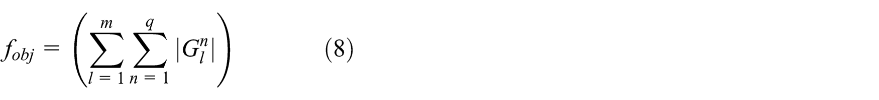
During updating stage, if the new harmony vector is better than the worst harmony vector in harmony memory in terms of the objective function defined in equation (8), the new harmony is included in the harmony memory, and the existing worst harmony is excluded from the harmony memory. Finally, if the stopping criterion or maximum number of improvisation (NI) is satisfied, the computation is terminated. Note that for the suspected mode identification, only binary part of the CHS is utilized.
Experimental study
Mobile robot system description
In order to verify the proposed sequential fault diagnosis approach, a test on a mobile robot system is conducted. The robot system, as shown in Figure 2, consists of direct current (DC) motor, gear, belt, oil pump, hydraulic actuator, steering mechanism, and tires. The steering power is provided from the hydraulic actuator which generates pressure difference to push the oil piston inside the actuator. The oil piston is connected to the steering mechanism. The pump is driven by the DC motor through the belt and converts mechanical speed to proportional oil flow. Four sensors, that is, two pressure sensors, an absolute encoder, and an incremental encoder, are installed to measure various signals in the system. The absolute encoder is utilized to measure the steering angle, and the incremental encoder is adopted to measure the DC motor speed on the reducing output shaft.

Test bed for mobile robot system.
The DHBG of the robot system is shown in Figure 3. A DHBG is a HBG that is assigned with proper set of causalities, such that the causality of every active BG component is valid and consistent at all modes. In this figure, source

where

DHBG model of the robot system.
Physical parameters of the mobile robot system.

DC: direct current.
From the DHBG of the system, three independent AGARR equations are derived. First, consider the constitutive relation of junction

Tracking back the causal paths on DHBG, the unknown variables

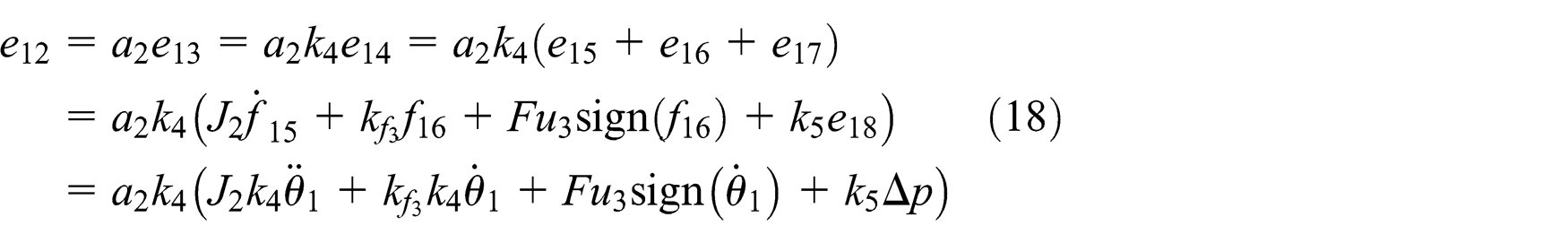
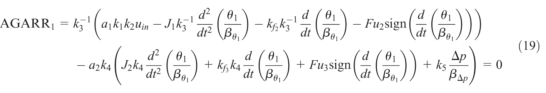
Substituting equations (17) and (18) into equation (16) yields
Next, consider junction 01 with sensor

The flow variables


Combining equations (20)–(22) and equation (15), AGARR2 can be expressed as

Finally, consider junction 15 attached with flow sensor

Unknown variables


The third AGARR can be obtained according to equations (24)–(26)

Table 2 is the MD-FSM which represents the cause–effect relations between component faults and residuals. Table 3 is the MCSM which represents cause–effect relations between mode changes and residuals. It is worth noting that more sophisticated model can be developed for the mobile robot system if effects of nonlinear phenomena such as saturation or friction are considered. At the same time, the model complexity is increased where many physical parameters related to nonlinear phenomena (e.g. the flat tire fault is represented by the change of friction coefficients) could be possible fault candidates. Therefore, fault isolation will lead to many fault candidates which adds to the complexity of fault identification. In order to achieve the tradeoff between the model accuracy and fault diagnosis complexity, the model with linear friction is preferred as long as the fault diagnosis performance is acceptable.
MD-FSM at mode [a 1 a 2] = [1 1].
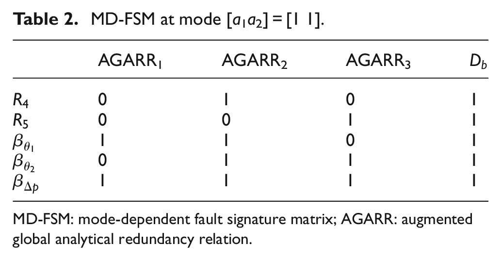
MD-FSM: mode-dependent fault signature matrix; AGARR: augmented global analytical redundancy relation.
MCSM of the robot system.

MCSM: mode change signature matrix; AGARR: augmented global analytical redundancy relation.
Experimental results and discussions
The robot system is an open-loop system. The motion of the DC motor of the system is generated by a current-modulated pulse width modulation (PWM) voltage from a current amplifier. The command input signal is defined as follows (in V)

During physical parameter identification of the mobile robot system under normal condition, a sine signal
Note that in closed-loop systems, controllers try to hide fault effects, and thus, it is usually impossible to find faults by simply observing the system outputs. 20 For example, a tank system with a controller to maintain a constant level, if a tank leakage fault occurs, the controller tries to hide fault effects by increasing its output to maintain a constant tank level. If one observes the system output, that is, the tank level, the fault cannot be detected. However, in DHBG-based fault diagnosis method using the AGARRs, the controller cannot hide the fault effects because AGARR residuals remain sensitive to fault hidden by the action of the closed-loop controller. Let us still consider the closed-loop tank system, if a leakage fault occurs, the AGARR residual will exceed the threshold because the residual of AGARR is persistently sensitive to the leakage fault. Thus, there is no difference between fault detection in closed-loop systems and the one in open-loop systems when DHBG-based methods are used.
Three fault scenarios are considered in the experiment. In the first fault scenario, an abrupt internal leakage fault at t = 32 s with faulty value
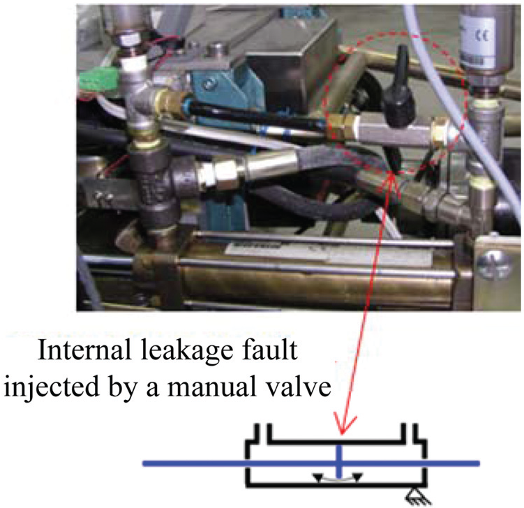
Injection of internal leakage fault by a manual valve.
Figure 5 illustrates the residual responses under the abrupt internal leakage fault and intermittent sensor fault where dashed lines are the thresholds. At 32 s, a CV = [0 1 0] is observed from residuals. It is known that the CV is not caused by fault mode from Table 3. As a result, the CV is caused by a component fault, that is, an internal leakage fault in
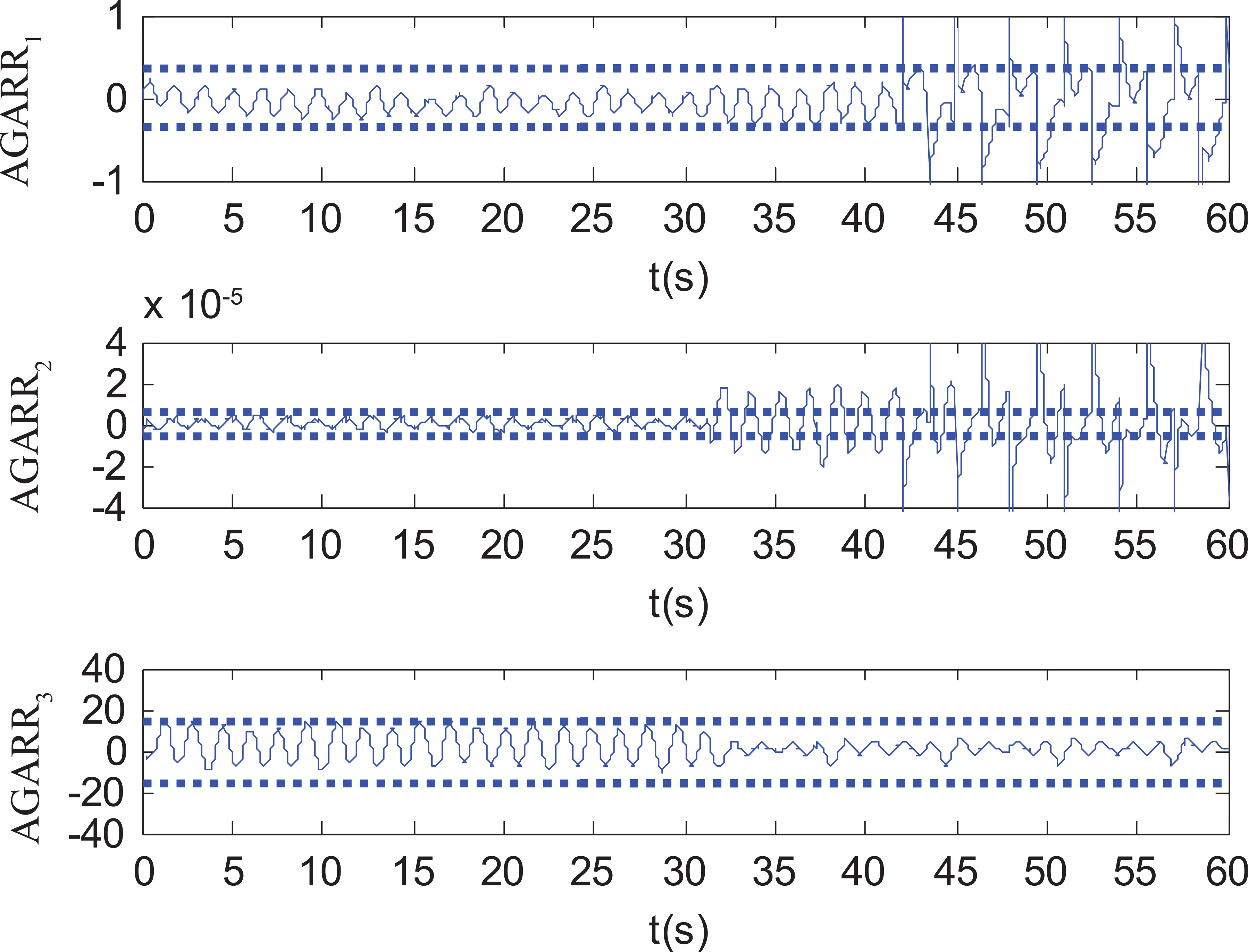
Residual responses under asynchronous faults: an abrupt internal leakage fault and an intermittent sensor fault in
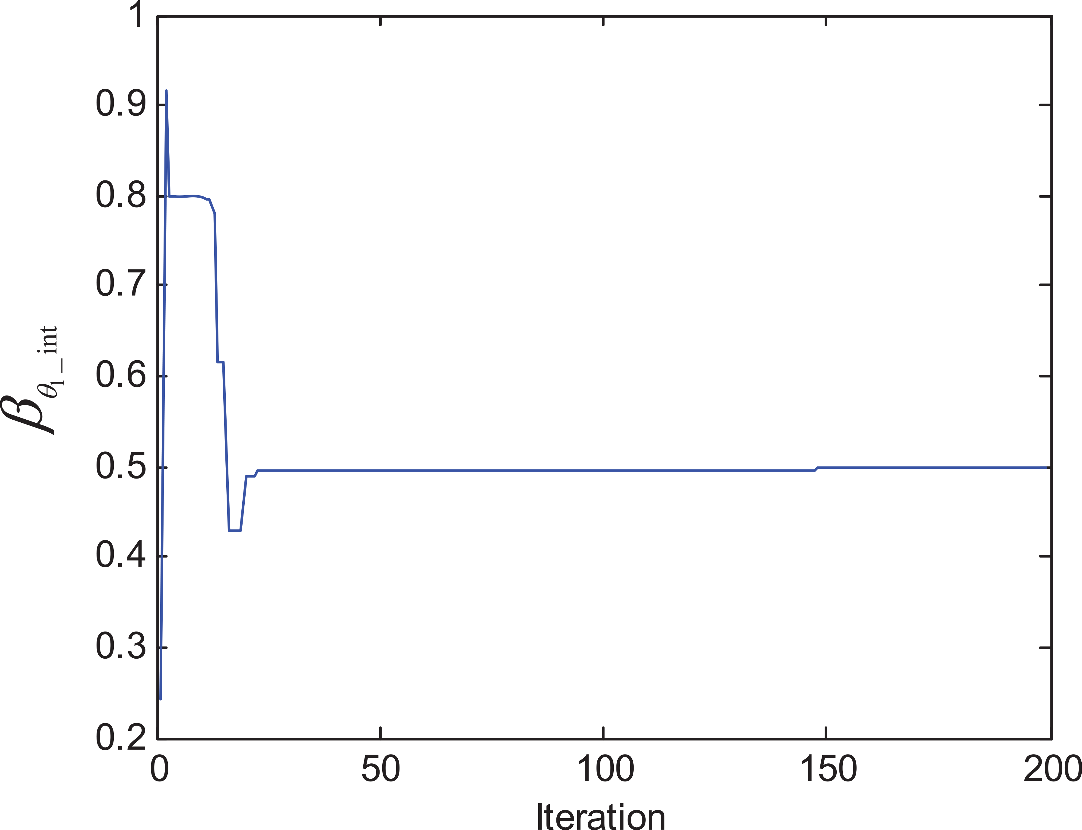
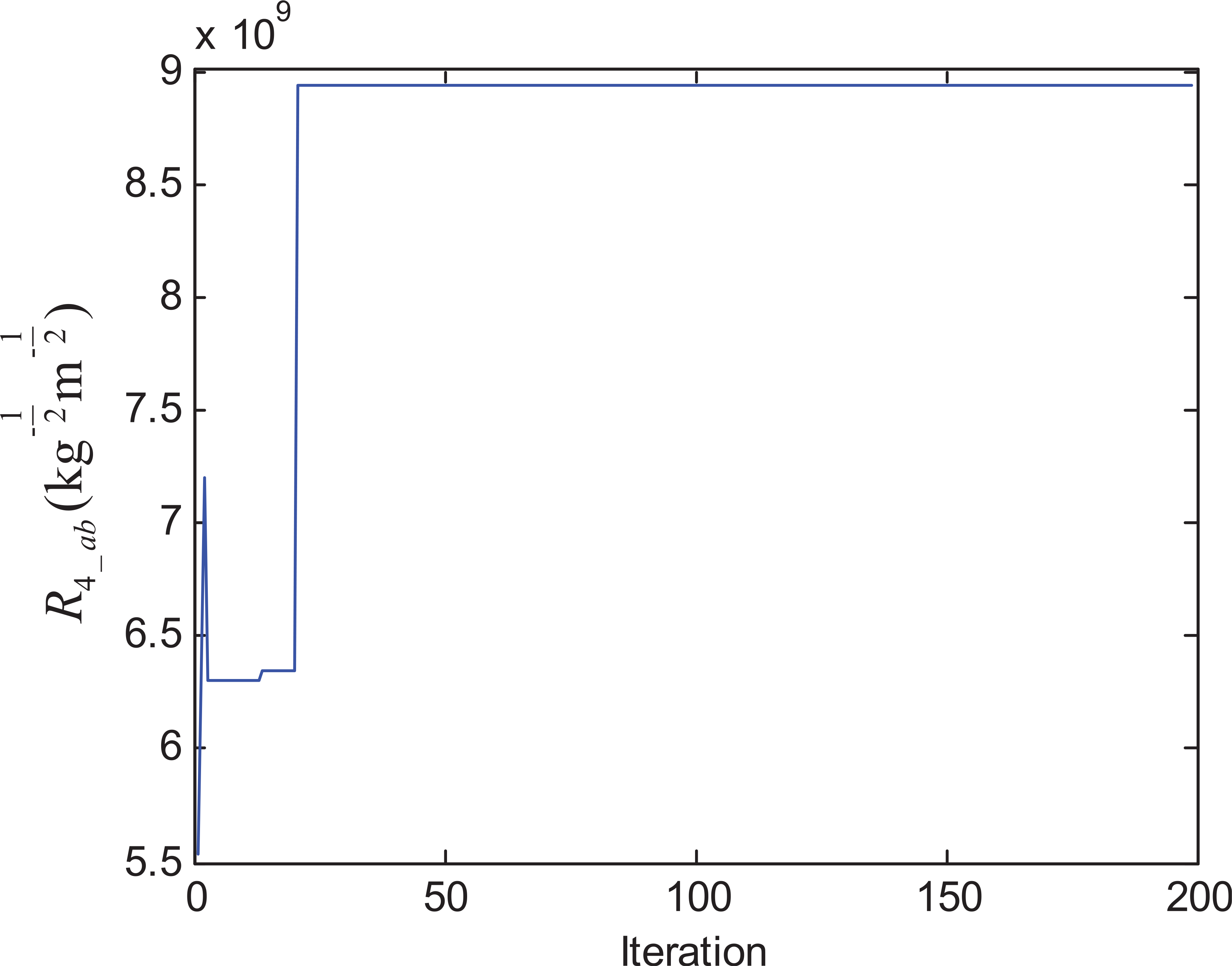
Since the knowledge of the fault type is unavailable in advance, the CHS algorithm is enabled for SFI1 to identify the fault type with corresponding information. The parameters associated with CHS are chosen as: HMS = 100, PAR = 0.05, HMCR = 0.8, and NI = 200. Figures 6 and 7 show the identification results of SFI1. From these figures, it is known that the internal leakage fault is abrupt because

Identification for

Identification for
Identification for

Identification for

Identification for
For the second fault scenario, an abrupt internal leakage fault with faulty value

Residual responses under asynchronous faults: an abrupt internal leakage fault and an abrupt sensor fault in

Identification for fault mode.

Identification for

Identification for
Identification for

Identification for
Since the observed CV = [1 1 0] has the ability to hide internal leakage fault with CV = [0 1 0] if sensor fault in

Response of SLR2.

Identification for

Identification for
In the third fault scenario, an actuator fault (i.e. a burnt DC motor fault) is considered. This fault is a fault mode where no power is delivered to the system upon the fault occurrence. The burnt motor fault is injected at t = 31 s by disabling the motor. Figure 20 shows the residual responses under the fault. Around t = 31 s, a CV of [1 0 0] is detected. Since the CV is unique according to Tables 1 and 2, it is concluded that this fault signature is caused by the burnt motor fault. Therefore, the burnt motor fault is detected and isolated.

Residual responses under fault mode: burnt DC motor.
In order to demonstrate the superiority of the proposed CHS-based sequential fault identification method, comparison study with genetic algorithm (GA), adaptive genetic algorithm (AGA), and hybrid differential evolution (HDE) is conducted. All methods are tested on the same experimental data which are collected for SFI1 of the first fault scenario. In GA, all possible solutions are encoded into binary chromosomes where
For selection and reproduction, individuals with the highest fitness values are kept in the next generation, while those with the lowest fitness values are abandoned. The high-quality individual has a greater chance to recombine with other individuals to reproduce offspring according to the genetic operators of crossover and mutation. The major structure of AGA is same with the one of GA. The only difference between them is that AGA is able to adaptively tune the crossover and mutation rates based on the performance of the current genetic operators. 21 It can adjust the balance between the exploration and exploitation of the solution space.
In HDE, real-valued differential evolution (RDE) is adopted to find
To perform a fair comparison, the population size and the maximum iteration of all approaches are set equal to 100 and 200, respectively. For each algorithm, 50 independent runs are carried out. Table 4 summarizes the minimum objective function
Performance comparison of different methods.
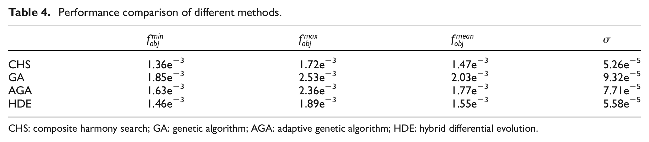
CHS: composite harmony search; GA: genetic algorithm; AGA: adaptive genetic algorithm; HDE: hybrid differential evolution.
Conclusion
In this article, a new sequential fault diagnosis method to handle asynchronous distinct faults using DHBG and CHS is proposed. The monitored system has various fault types including fault mode, abrupt fault, and intermittent fault. The fault-type information is unknown in advance, and the SFI algorithm is reactivated during monitoring process based on two activation conditions. The proposed method is able to handle continuous variables and binary variables simultaneously. The developed method can identify the fault information as early as possible for future maintenance purpose. Three different fault scenarios have been experimentally tested on a mobile robot system to illustrate the effectiveness of the proposed method.
Footnotes
Academic Editor: Zhijun Li
Declaration of conflicting interests
The author(s) declared no potential conflicts of interest with respect to the research, authorship, and/or publication of this article.
Funding
The author(s) disclosed receipt of the following financial support for the research, authorship, and/or publication of this article: This work was supported by the Huangshan Young Scholar Fund of Hefei University of Technology under grant no. 407037159.