
Abstract
Studies indicate that driving circuit and drift error in resonance frequency influence the sensitivity of micromechanical resonant electric field sensors. This study proposes an electric field sensor with a comb structure for driving and sensing. A dynamic model is built for the microsensor, which analyzes the behavior and sensitivity of the system on different closed-loop self-excited circuits using the averaging method. Theory and simulation results show that with the use of a proportional–integral controller, the sensitivity remains constant regardless of the variations in the resonance frequency of the shielding layer and Q-factor. The sensitivity is higher with a suitable proportional–integral controller than without a proportional–integral controller. If the parameters of the proportional–integral controller fail to satisfy the constraint relationship, output voltage becomes unstable, and the sensitivity is distorted.
Introduction
Electric field sensors are used in meteorology, aerospace, and other fields. These sensors have attracted the attention of smart grid industries because of their potential application in measuring power system voltage, detection of ice accretion in high-voltage lines, identification of insulator defects, and lightning warning.
Compared with traditional electric field sensors, microelectromechanical system-based electric field sensors (MEFSs) are small and lightweight, thereby facilitating integration and reducing power consumption. Electrostatic comb-driven MEFSs1,2 and thermally driven MEFSs3,4 have been developed using different methods, mostly using strip sensing electrodes and exhibiting similar induction structures. The shutter is placed above the sensing electrodes. The vibration structure on the shutter layer of MEFS must continuously detect resonance. Sensitivity is an important property to consider in sensor design, and previously proposed sensors present disadvantages,5–7 such as susceptibility of sensitivity to change because of material fatigue and the variations in the working temperature. The changes in sensitivity lead to the changes in output voltage, which causes difficulty in determining whether the change in output voltage is caused by the electric field or by other factors. Sensor performance cannot meet the requirements of high-precision measurement.
This study proposes a two-part design of a resonant electric field sensor: the structural design and the closed-loop control circuit design. First, the sensor includes two critical layers, namely, the resonance shielding layer and the sensing layer. We use the comb capacitance to convert voltage into a static driving force. In addition, comb capacitance and interface circuit can convert the displacement of the resonance beam into output voltage. This type of symmetric capacitance structure reduces the nonlinearity of these conversions. Second, several studies incorporated a self-sustained oscillation loop scheme into microelectromechanical systems resonant sensors. These studies used automatic gain control (AGC) technology to maintain a constant amplitude of vibration in the vibration structure. However, the nonlinear problem of sensitivity was not considered in the design. The proposed MEFS is powered by a self-sustained oscillating loop circuit. We adopted the proportional–integral (PI) controller to maintain the sensitivity of the sensor. We employed the averaging method to address the high degree of nonlinearity of the system. The stability of the system and the nonlinearity of sensitivity with the controller were analyzed and compared. The theoretical and simulation results indicate that the method is feasible and the proposed design exhibits high sensitivity when material fatigue is present and the Q-factor is changed.
Principle of MEFS and Q-factor tuning
Figure 1 shows the operating principle of MEFS. The laterally vibrating grounded shutter periodically shields and exposes the sensing electrodes; thus, an alternating current (AC) proportional to the external electric field strength is generated. 6

Operating principle of an electric field microsensor.
Normal electric field

where

When the electrostatic force is sinusoidal, equation (2) can be described as follows 7

where

where
We can adopt comb capacitance or parallel plate capacitor to achieve the conversion of voltage into static driving force, as well as the conversion of the displacement of the resonance beam into output voltage. The conversion in the parallel plate capacitor is nonlinear; 8 thus, we choose the type of symmetric capacitance structure to reduce conversions of nonlinearity. The entire resonance shielding layer is shown in Figure 2.
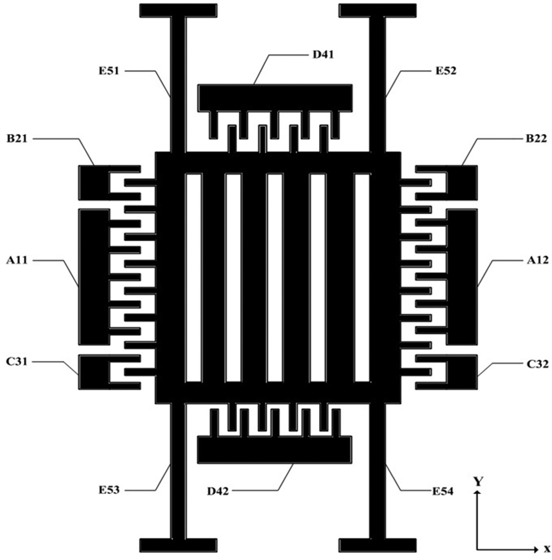
Shutter layer of the proposed electric field microsensor.
The shutter layer of the proposed new MEFS consists of fixed combs A11, A12, B21, B22, C31, C32, D41, and D42, as well as the transferred frame E5. A11 and A12 are differential drive combs. B21, B22 and C31, C32 are differential combs that detect the electrostatic drive force. When a fabrication error occurs, D41 and D42 are connected to the direct current (DC) voltage; D41 and D42 are combs that adjust the resonant frequency of the vibratory shutter through negative electrostatic stiffness. 8
When only the electrostatic force of the drive is present in the vibratory shutter, the following dynamic equation is used

where
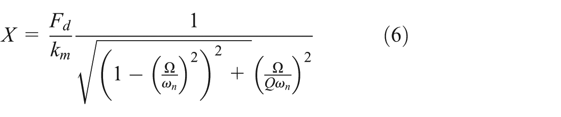
When
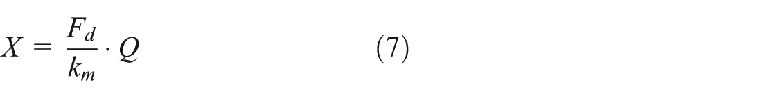
Equation (7) indicates that under the resonance states of the vibratory shutter, a larger Q-factor produces high sensitivity. The sensing layer includes two sets of cross-symmetrical electrodes, namely, F61 and F62. This design can eliminate common mode system noise in this sensor. The electrode is shown in Figure 3. The two groups of the same interface circuit are connected to the electrodes F61 and F62.
Sensing layer of the proposed electric field microsensor.
Self-sustained oscillation loop for MEFS
Self-sustained oscillation loop control for MEFS
The proposed MEFS is vacuum-packaged, and a self-sustained oscillation loop is adopted to power the vibratory shutter. The vibration velocity of the comb is converted into the variation in capacitance, and a transimpedance amplifier is used to convert the variation in capacitance into output voltage. The two similar transimpedance amplifiers are connected to the electrodes F61 and F62. Instrument amplifiers are used to amplify the differential mode signal from the two transimpedance amplifiers. The autogain controller consists of a rectifier, a low-pass filter (LPF), an inverted adder, and a PI controller. Figure 4 shows the equivalent block diagram of the entire system. A transimpedance amplifier replaces the two fully differential amplifiers and instrumentation amplifier circuit. The output signal of the transimpedance amplifier
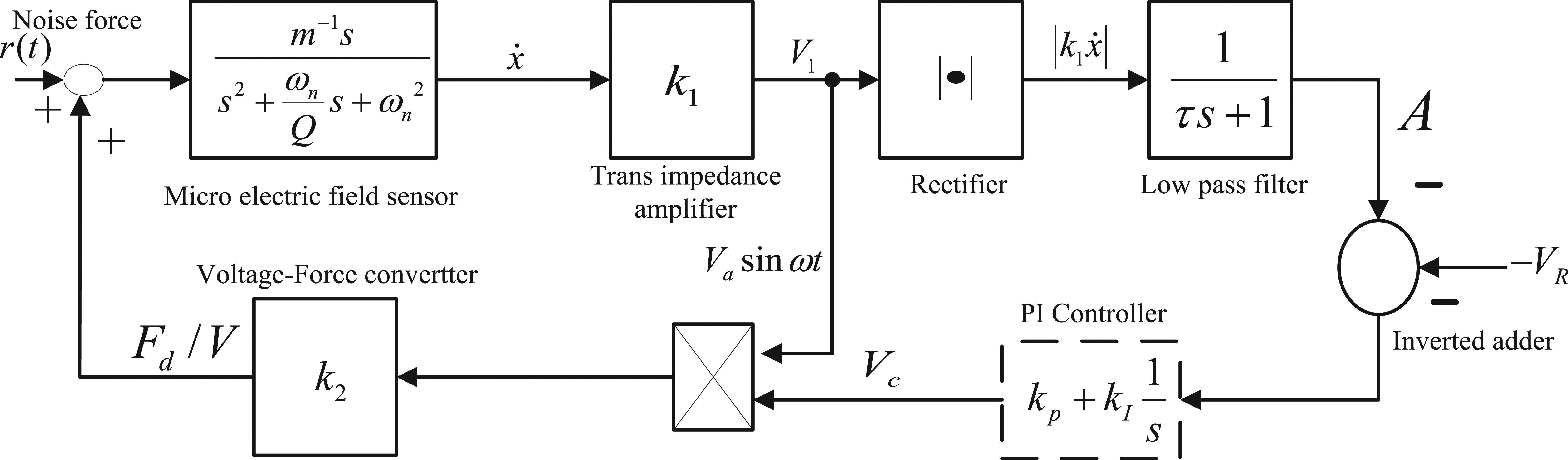
Block diagram of the self-sustained oscillation loop system.
The proposed MEFS features a second-order spring–mass damper system with a dynamic behavior described by
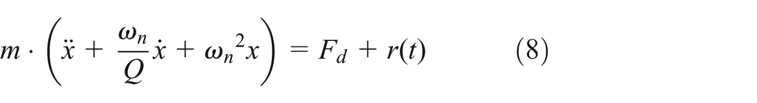
After power-up, the white noise voltage is generated and becomes larger than the equivalent drive voltage; however, the equivalent drive voltage immediately exceeds the white noise voltage. The influence of the electrostatic force

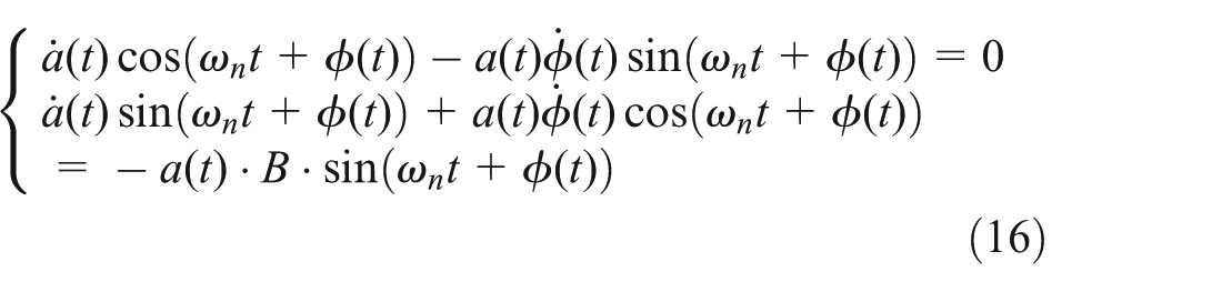
To analyze the transient behavior of the system, we define the position of the vibratory shutter as follows9,10

where
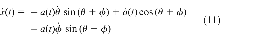
To determine

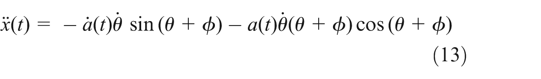
The acceleration is obtained by differentiating equation (11) with respect to time; thus
The driving force

On the basis of the structure of the rectifier, LPF, and the phase shifter, the entire self-sustained oscillation system without the PI controller (Figure 4) is described as follows

By assuming that


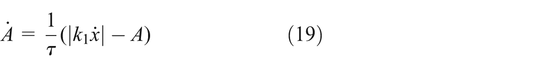
For slowly time-varying systems, some equations are established in accordance with the principle of the average cycle method, 11 as follows
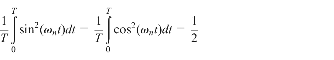


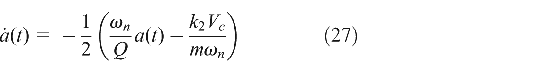
Differential equations (16)–(19) are averaged with respect to


The Jacobian linearization at these equilibria is


When equation (24) is satisfied, the linearized system near equilibrium

The

According to equation (25), the sensitivity
Figure 4 shows a PI controller applied in the amplitude control loop.

where


The new equilibrium of the averaged system described is


The characteristic equation for the new self-sustained oscillation system is
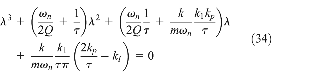
where

On the basis of the indirect method by Lyapunov, the equilibrium of the nonlinear averaged system is determined to be asymptotically stable within a neighborhood if and only if equation (35) is satisfied. For the original exact differential equations, this condition means that the solution of oscillation at the natural frequency of the resonator is stable and attractive. Equation (35) provides a criterion for selecting the parameters

According to equation (36), the sensitivity
Simulation and experiment
The microsensor is fabricated by deep reactive-ion etching bulk micromachining technology and silicon bonding technology. The structural material is single crystalline silicon with dense boron diffusion, and the substrate material is 7740# glass. The sensor is vacuum-packaged in a 14-DIP metal package. The Q-factor is approximately 1500 in this condition. Figure 5 shows that a simulation model without a PI controller is built with Simulink for the proposed MEFS.
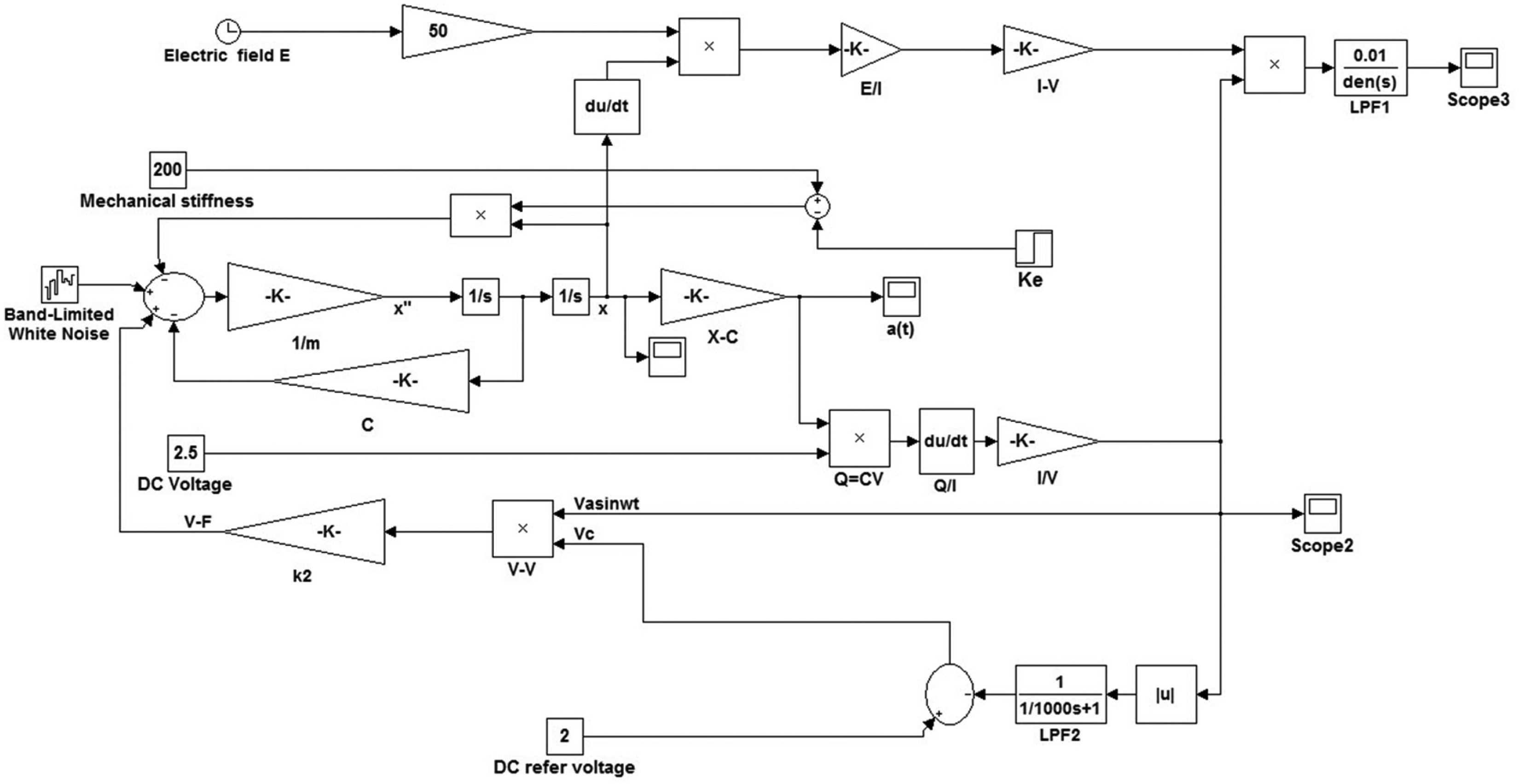
Self-sustained oscillation loop for the electric field microsensor based on SIMULINK.
The applied input disturbance is external stiffness
Parameters of the electric field microsensor.

Table 1 also lists the numerical values of the parameters used in the simulation. The critical value of the DC reference voltage

Output voltage with VR = 1 V and Q = 1500.

Output voltage with VR = 2 and 3 V.
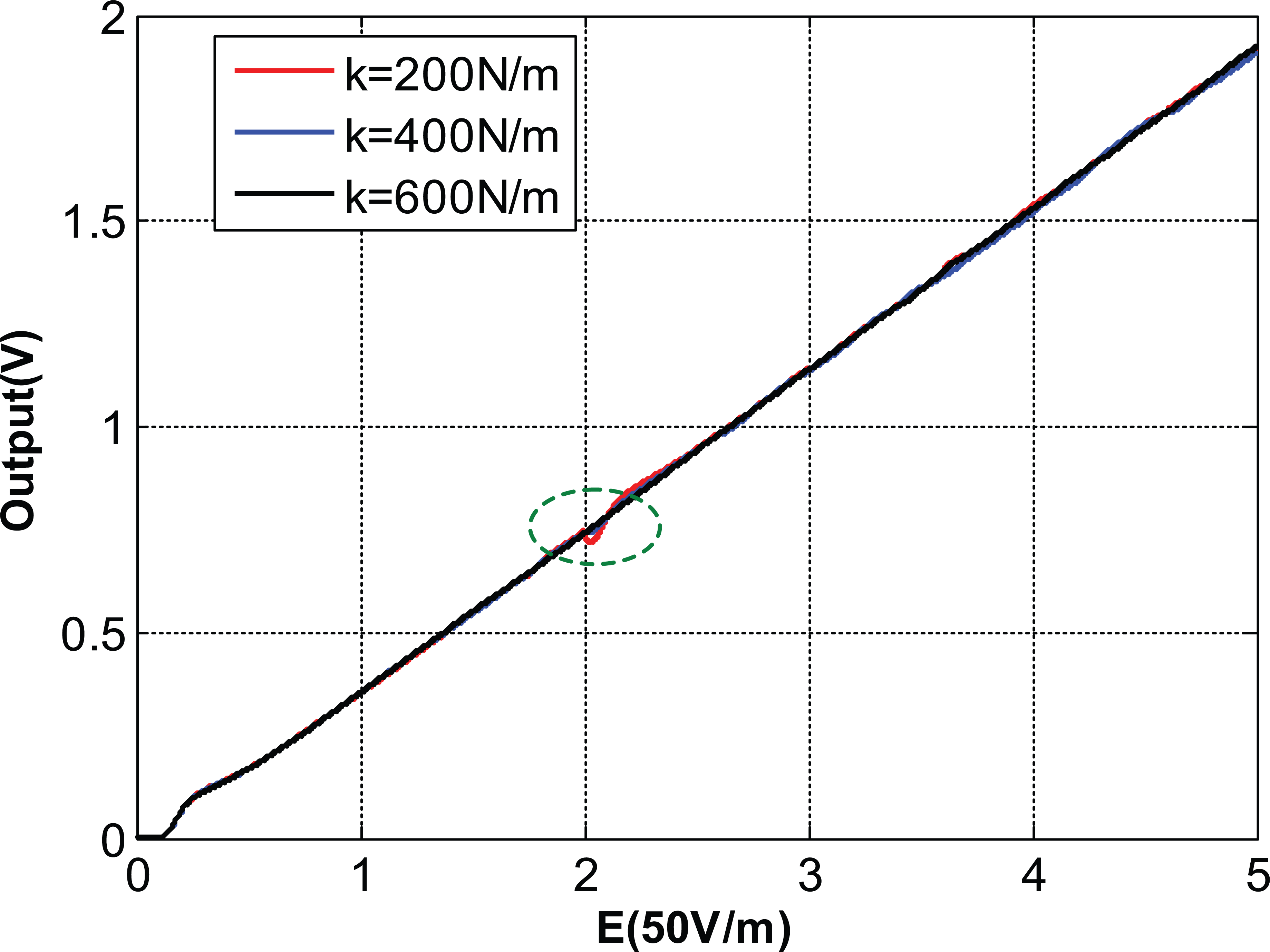
Figures 8 and 9 show the output voltage with varying stiffness when the Q-factor is 1500. The increases in sensitivity and nonlinearity are limited with varying stiffness. At Q-factor = 600, the nonlinearity markedly increased with varying stiffness, as shown in Figure 9. According to equation (25), without the PI controller, the larger the Q-factor, the smaller are the sensitivity and the nonlinearity. The simulation results are consistent with equation (25). The dynamic characteristics of output voltage are determined by
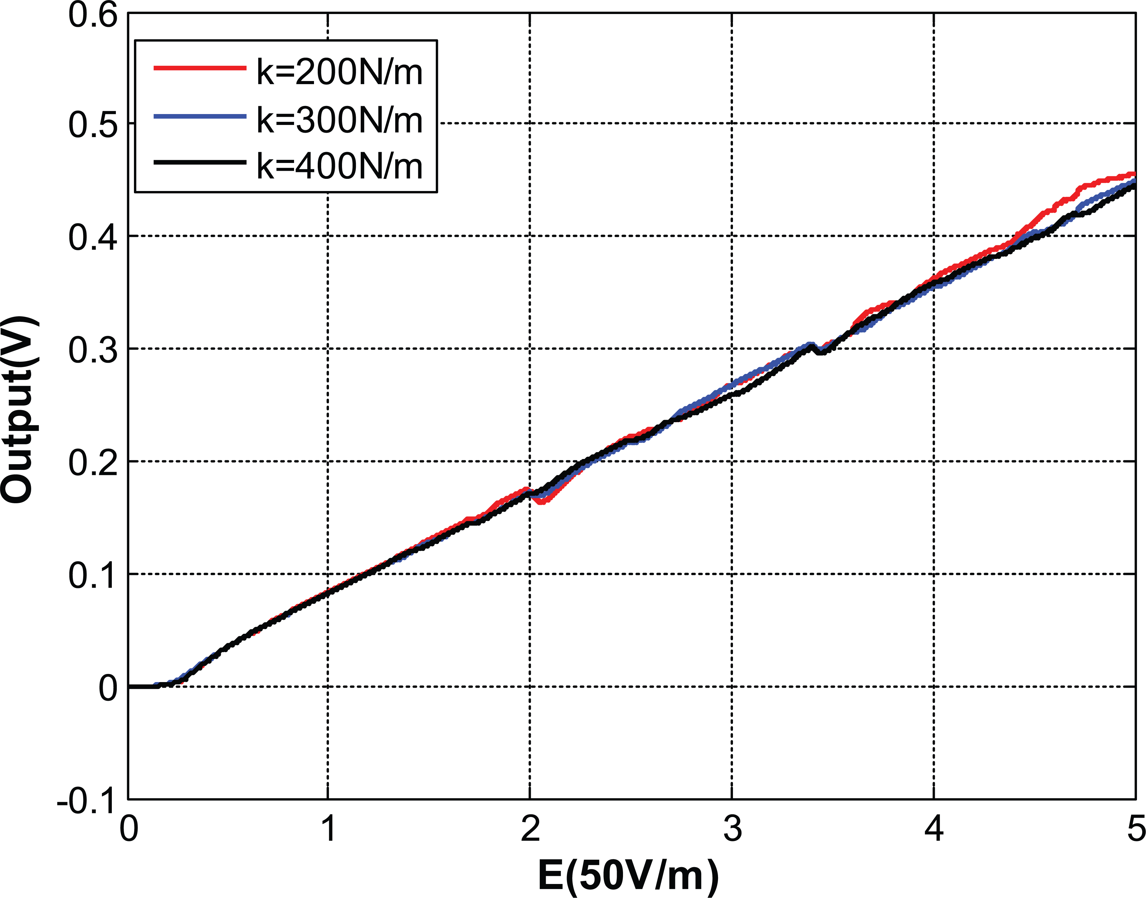
Output voltage with different design stiffness (Q = 1500).

Output voltage with different design stiffness (Q = 600).

Output voltage with varying
When the PI controller is added into the self-sustained oscillation loop for the electric field microsensor as shown in Figure 11, the other parameters remain the same,
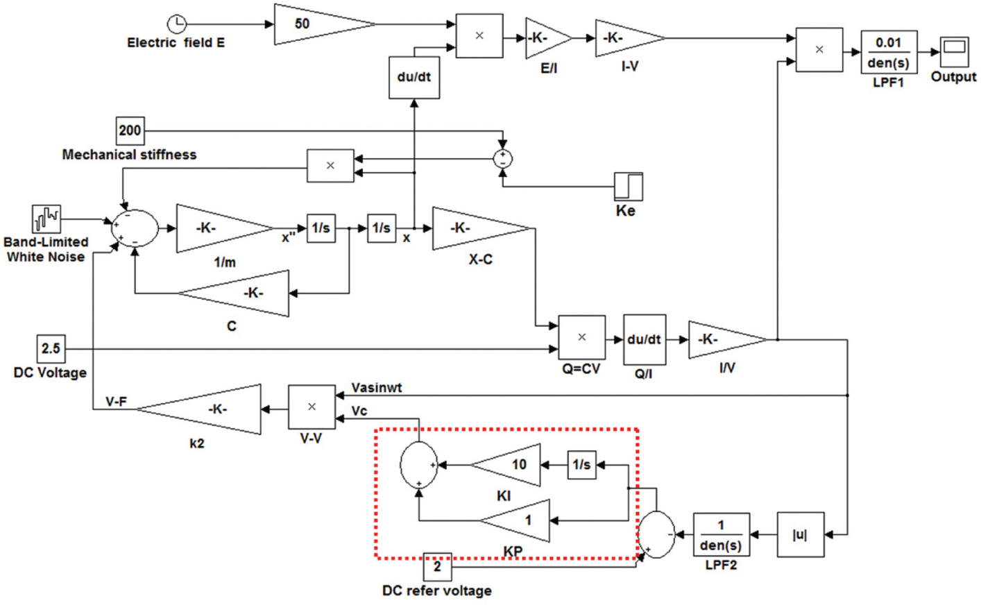
Self-sustained oscillation loop for the electric field microsensor with the PI controller.
Zoom output voltage (

Zoom output voltage (
Figure 14 shows the sensitivity with and without the PI controller, with the other parameters remaining the same. Given the same DC reference voltage

Sensitivity with and without the PI controller.
Given the nonlinearity of the entire system, we use the averaging method to approximate and analyze the behavior of the system. We use two stable equilibrium points of the system as equations (21) and (31)–(33). According to equations (31) and (33), the second stable amplitude of vibration at the equilibrium point
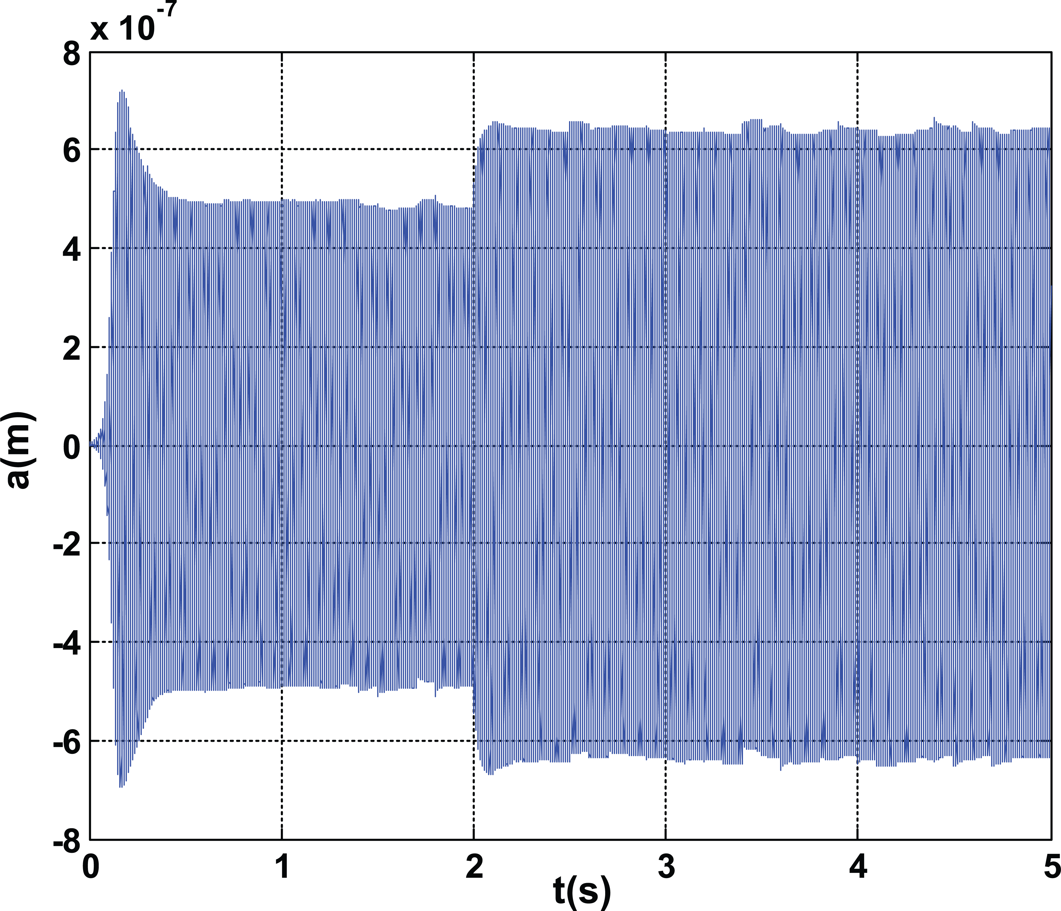
Stable equilibrium points
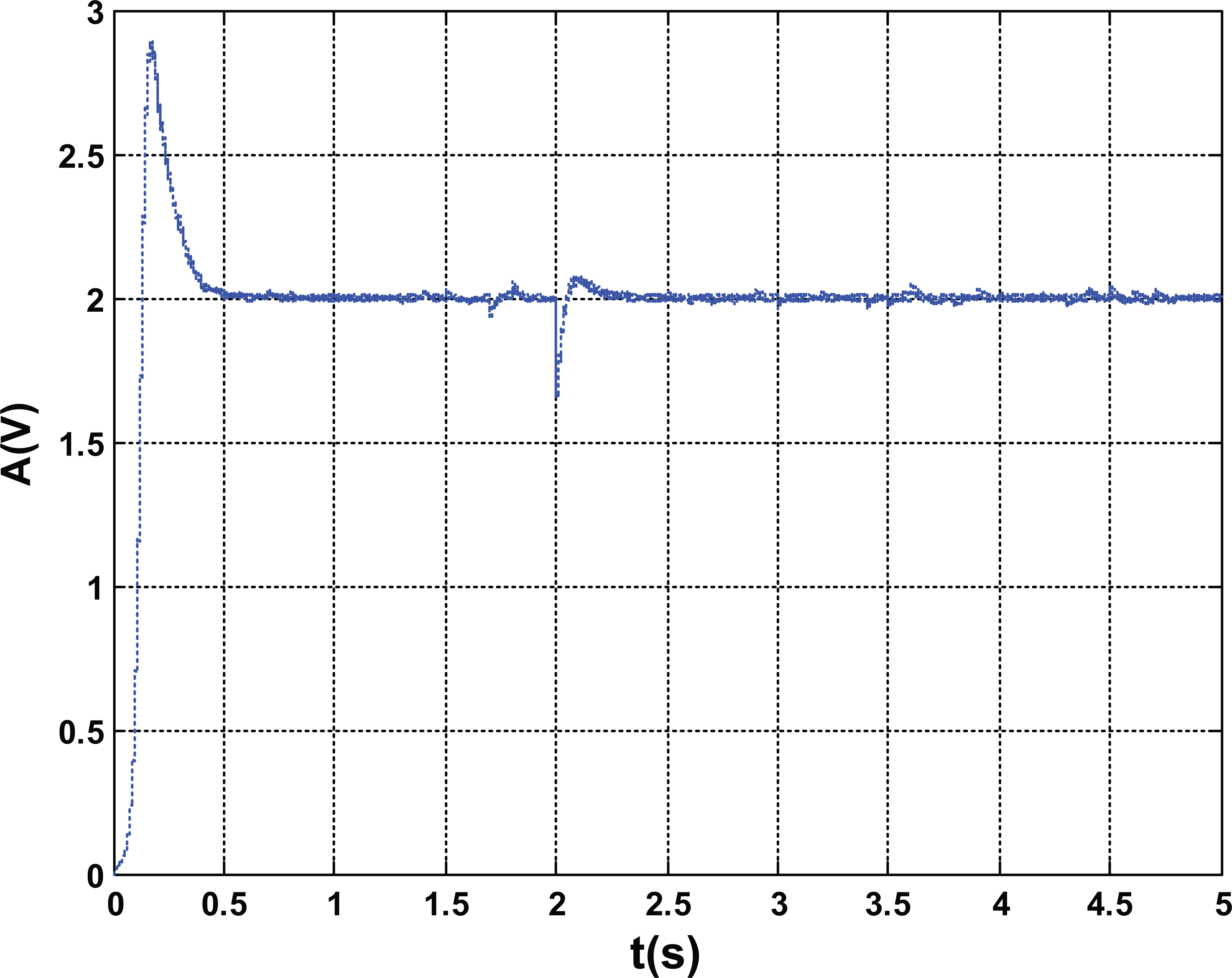
Stable signal
The stability of the output voltage of the system depends on the parameters of the controller and whether equation (35) is satisfied. Figure 17 shows the output voltage when equation (35) is not satisfied. The output voltage does not converge, causing difficulty in determining whether the change in output voltage is caused by the electric field or by other factors.

Output voltage when equation (35) is not satisfied (kp = 1, kI = 1500, and
Conclusion
To design a micromechanical resonant electric field sensor with high sensitivity, we propose a two-part design, including structural design and the measurement and control of circuit designs. On the basis of the theoretical analysis, comb capacitance structure can successfully reduce the nonlinearity of the two conversions. A dynamic model is built for the microsensor, which analyzes the behavior and sensitivity of the system on different closed-loop self-excited circuits using the averaging method. The theory and simulation results show that with the use of a PI controller, the sensitivity remains constant regardless of the variations in the resonance frequency of the shielding layer and the Q-factor. The sensitivity is higher with a suitable PI controller than without a PI controller. If the parameters of the PI controller fail to satisfy the constraint relationship, the output voltage is unstable and the sensitivity is distorted.
Footnotes
Academic Editor: Xiaotun Qiu
Declaration of Conflicting Interests
The author(s) declared no potential conflicts of interest with respect to the research, authorship, and/or publication of this article.
Funding
The author(s) disclosed receipt of the following financial support for the research, authorship, and/or publication of this article: This work was supported by the Natural Science Key Fund for Colleges and Universities in Jiangsu Province (No. 13KJB510017), the Jiangsu Province Natural Science Fund (No. BK20131001), and the Open Fund of the Key Laboratory of Testing Technology and Manufacturing Process, Ministry of Education (No. 14zxzk02).