
Abstract
Insufficient technologies made good integration between the die components in design, process planning, and manufacturing impossible in the past few years. Nowadays, the advanced technologies based on Standard for the Exchange of Product model data are making it possible. This article discusses the three main steps for achieving the complete process planning for prismatic parts of the die components. These three steps are data extraction, feature recognition, and process planning. The proposed computer-aided process planning system works as part of an integrated system to cover the process planning of any prismatic part die component. The system is built using Visual Basic with EWDraw system for visualizing the Standard for the Exchange of Product model data file. The system works successfully and can cover any type of sheet metal die components. The case study discussed in this article is taken from a large design of progressive die.
Introduction
The die design and manufacturing industry represents a good application for the integration between the computer-aided design (CAD), computer-aided process planning (CAPP), and computer-aided manufacturing (CAM). The competition in this industry decreases the time consumed in design and manufacturing and thus contributes to the success of the factory. The idea of integration between these different items of die industry is vital and has been dreamed for many years ago. Many efforts have been made over the past years to cover this integration.
One of the earliest efforts was between 1991 and 19931–3 by Lee from NTU, Singapore, and with cooperation with NUS, Singapore. The first effort for making a specialist CAPP system for progressive die components is called “IKOOPP” or intelligent knowledge-based object-oriented process planning. The lack of technologies made this effort insufficient to apply in the industry.
Many years later, in 2003, 4 after the increase in using the feature recognition based on data extraction from standard B-rep files such as Initial Graphics Exchange Specification (IGES) and Standard for the Exchange of Product model data (STEP), it was possible to recognize the part features which directly guide the required process planning of the part.
Similar work comes from Spain, by Joan Vivancos Calvet et al.5–8 as they constructed an integrated system from the die design until the manufacturing of the die components. They chose the progressive die as their case study for this integrated system, as this kind of die requires a highly sophisticated degree of design and manufacturing.
Chaturvedi and Allada, 9 in 1999, discussed an integrated system under AutoLISP for AutoCAD. The proposed system is specified only for punch and dies. The system includes many standard punch shapes stored under a sliding menu for AutoCAD. Kumar and Singh, 10 in 2007, constructed a knowledge-based system for selection of the progressive die components for the assembly of progressive die. Chithajalu Kiran Sagar et al., 11 in 2013, described a complete die design for hook hood lock auxiliary catch.
Abouel Nasr et al., 12 in 2014, discussed an integrated CAD/CAPP system for sheet metal blanking die. The proposed CAPP system is constructed based on the three main steps for extracting, recognizing, and building the automated process planning for the prismatic die components. Roja and Andhare, 13 in 2012, suggested a CAPP and cost estimation system in blanking die components. Alting and Zhang 14 presented a comprehensive survey of several known CAPP systems, but they mentioned some doubts regarding the effective implementation of these systems. ElMaraghy et al. 15 presented the future research trends in CAPP mainly focused on CAD/CAPP integration, CAPP, and production planning and control (PPC) integration and intelligent process planning systems. Leung 16 classified the process planning techniques into 12 main areas according to their sequence of development stages. Xu et al. 17 discussed a more recent research in CAPP systems during the last decade. The author also presented a statistical analysis of CAPP papers published during 2001–2009 with a concept of subject strength of journal and technology impact (depending on citation count) based on e Elsevier’s Scopus abstract and citation database.
Moreover, STEP-NC, as defined by the International Organization for Standardization (ISO), ISO 10303-AP238, offers accurate and complete product definition data from product design all the way to the machine tool. The current discrete part manufacturing does not produce parts based on all the product information that has been described upstream by the design process. Instead, the part fabrication process starts with the CAD part design, incorporates CAM feature-based machining operations, and then translates the machining operations into simple machine tool motion primitives or “M” and “G” codes. 18
A lot of work has also been done in feature recognition of prismatic parts as Venkataraman 19 presented a graph-based framework for feature recognition. The novelty of this framework lied in the usage of a rich set of attributes to recognize a wide range of features efficiently. Han Kang and Choi 20 presented integrating feature recognition and process planning in the machining domain to achieve the goal of CAD/CAM integration. Ismail et al. 21 proposed a rule-based approach for the recognition of hole from STEP file using geometry and topology formation from B-rep model. Holland et al. 22 proposed a pattern recognition method to transform the surface boundary model of a component into an attributed adjacency graph (AAG). Lu 23 proposed an algorithm for the identification of design and machining features from a data exchanged part model. Haque 24 presented a methodology in which the geometric information of a rotational part is translated into manufacturing information through a Data Interchange Format (DXF).
Although a lot of effort has been made to address the issues in CAPP, feature recognition, and die design problems, there is a need to integrate CAD/CAM technologies through an independent and stand-alone CAPP system for die components. The significance of such a proposed application system based on STEP is its extensibility and integration with any existing CAD system. Moreover, the regular- and irregular-shaped features can be added easily.
The proposed system
The first step toward the development of CAPP system is the conversion of CAD features contained in the part into manufacturing features. These manufacturing features lay the foundation for feature-based process plan system. The proposed system is summarized in the following steps:
Step 1. Extract the geometric and topology entities for the designed object model from STEP file format.
Step 2. Extract topology entities in each basic surface and identify its type.
Step 3. Test the feature’s existence in the basic surface based on feature extraction algorithm.
Step 4. Identify feature type.
Step 5. Identify the detailed features and extract the related dimensional parameters.
Step 6. Identify the detailed machining information for each feature and the designed part.
Step 7. Assign tool access direction (TAD) to every feature so that it can be assigned to a definite setup.
The complete progressive die assembly is shown in Figure 1. The prismatic component of the die is selected for the illustration of the proposed system.
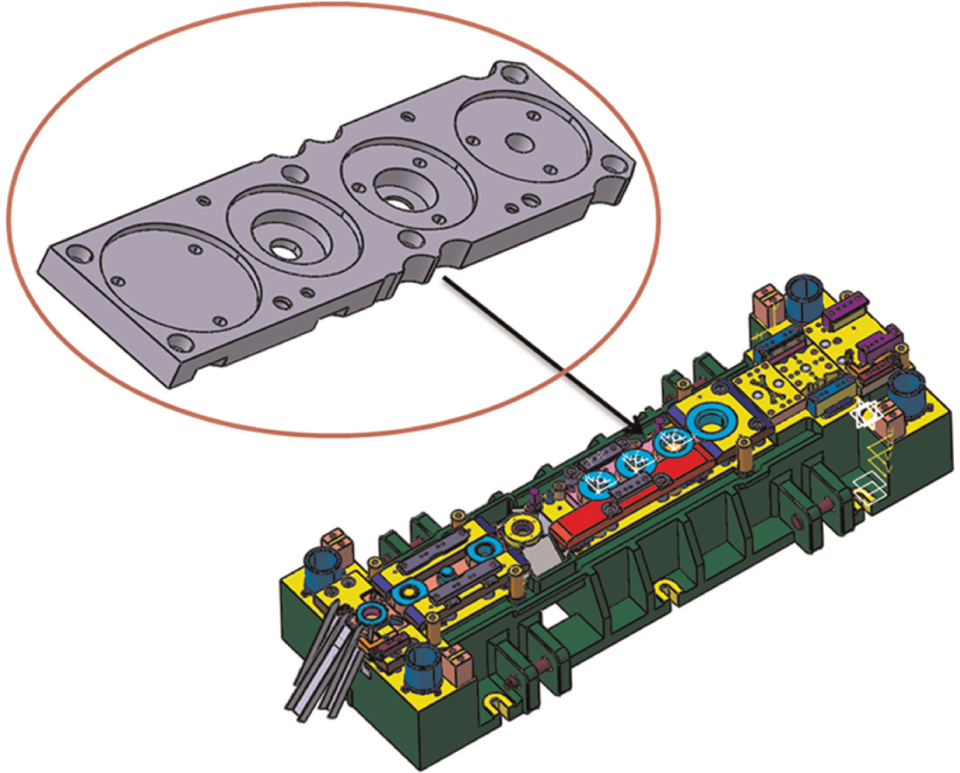
Selected die component plate in a large progressive die.
As shown in the figure, the complete die set has both prismatic and cylindrical components. In this article, only the prismatic part of the complete die set is taken into study. STEP AP 203 file is used here to extract geometrical and topological information of the part. Although STEP AP 224 standard is available for certain regular-shaped features, the die components have both regular- and irregular-shaped features. For example, the AP 224 defines a square slot (width = height) but not rectangular slot. Also, there is some difference between the circular hole and circular pocket based on diameter-to-height ratio. To address all these issues, a stand-alone feature recognition and process planning system is proposed for progressive die set. The system is now explained in the subsequent sections.
Geometric data extraction
The STEP AP 203 file represents the geometric and topological information of three-dimensional (3D) part model. The significance of using STEP AP 203 file is its compatibility with several known CAD systems. The data extraction process starts with the extraction of geometric and topological information from STEP AP 203 and redefining it as a new object-oriented data structure. Figure 2 presents the object-oriented class diagram for few STEP entities.

Class diagram.
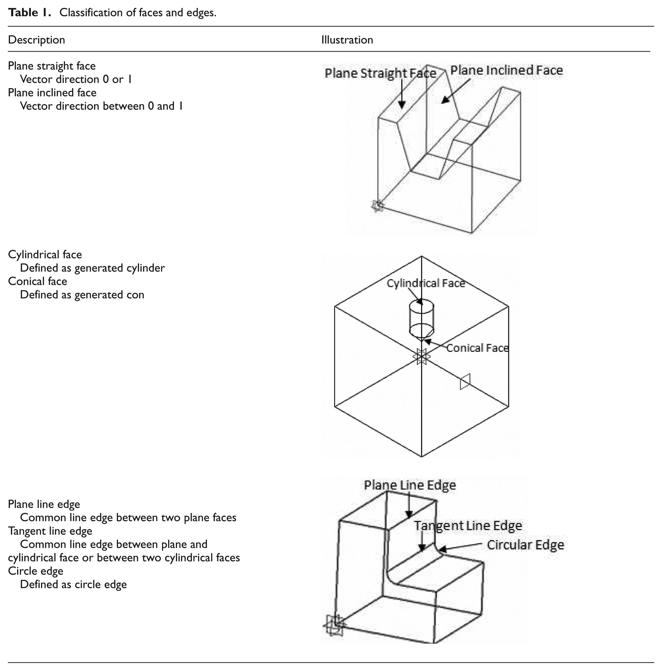
The object-oriented approach is well suited to communicate with the STEP file and makes a simple extracted file that contains all the information of B-rep solid in an easy and user-friendly format. This information identifies every shell in B-rep solid using its faces, loops, edges, and vertices along with the surface type and the normal vector direction. The faces, edges, and vertices have been given a unique ID number. Information regarding the face conditions (plane straight, plane inclined, cylindrical, conical), edge conditions (plane line, tangent line and circle edge), and face and edge directions is defined in Table 1. Moreover, the orientation, direction of a face vector, and external and internal loop determination are also established.
Classification of faces and edges.
Feature classification
The CAD features are classified as simple and compound features. The simple features represent the single entity as hole, slot, step, pocket, and so on, whereas in compound features, the multiple features are combined to represent as single entity. The compound feature system is a kind of feature interaction. There can be a feature interaction between these simple features or between simple and compound features. Figure 3 shows the feature interaction between two simple features (slot blind and hole through). The form features can further be classified as internal and external features based on their location on the part as Face_bound or Face_outerboundFeatures, respectively. The feature classification scheme is presented in Figure 4.

Feature interaction (simple).

Feature classification.
Feature extraction and recognition process
Feature recognition involves the identification and grouping of feature entities from a geometric model. Such “post definition” of features can be done interactively or automatically. Usually, identified entities (i.e. the recognized features) are extracted from the model and additional engineering information such as tolerances, and non-geometric attributes are then associated with the feature entities. 25
The feature extraction and recognition process starts with the extraction of feature faces from data extraction output file. A feature face extraction and dimensional algorithm is applied to extract these faces along with their dimensions. The algorithm is presented in the following steps:
Calculate the minimum and maximum x, y, and z values of the part by reading the edge loops of the geometric information file for the selected part.
Extract the faces that have constant coordinate value between minimum and maximum (value >min and <max) x, y, or z throughout the edge loop.
Extract the faces that have no constant coordinate values throughout the edge loop, and one or two coordinates are changing (throughout the edge loop) between the minimum and maximum x, y, and z values (value >min and <max) of the part.
Extract the faces that have no constant coordinate values throughout the edge loop, and two or three coordinates are changing (throughout the edge loop) between the minimum and maximum x, y, and z values (value >min and <max) of the part.
Extract and group the feature faces with respect to the common edge such that if Face 1 has common edge with Face 2 and Face 2 has common edge with Face 3, then Faces 1, 2, and 3 should be grouped.
The feature dimensions are calculated from all grouped feature faces such that:

Dimension calculation.
By applying the above algorithms, the feature faces are extracted and grouped along with their dimensions. Some part of the algorithm related to the minimum and maximum x values of the part (Step 1) is presented here as pseudo code for illustration purpose. Similar type of code is for the maximum and minimum y and z values.
The Pseudo Code for MinX
Read Points For All Edges Point()
Initialize Counter:
Initialize minx,P1,P2:
Counter = 0
minX = Absolute Value of Point(Counter)
P1 = Absolute Value of Point(Counter)
P2 = Absolute Value of Point(Counter + 1)
If P1 < minx Then
minx = P1
End If
If P2 < minx Then
minx = P2
End If
Increment The Counter:
Counter = Counter + 1
If Size of Point() = < Counter then
Go To Step 5
Else
Print “The Minimum Value Is minx”
Stop Processing
End If
The Pseudo Code for Max X
Read Points For All Edges Point()
Initialize Counter:
Initialize MaxX,P1,P2:
Counter = 0
MaxX = Absolute Value of Point(Counter)
P1 = Absolute Value of Point(Counter)
P2 = Absolute Value of Point(Counter + 1)
If P1 > MaxX Then
MaxX = P1
End If
If P2 > MaxX Then
MaxX = P2
End If
Increment The Counter:
Counter = Counter + 1
If Size of Point() = < Counter then
Go To Step 5
Else
Print “The maximum valueIs MaxX”
Stop Processing
End If
The next step is to formulate logical rules for recognizing these features. To differentiate between the hole blind and circular pocket, the radius-to-height ratio should be calculated. If radius-to-height ratio is less than 5, the feature is hole, otherwise circular pocket. The sample rules for simple and compound features are illustrated in Table 2.
Feature recognition rules.

Machining data and setup plan
The purpose of machining operation is to create the desired feature shape by removing the excess material from the workpiece. The most commonly used machining operations are turning, milling, drilling, boring, shaping, and so on. In this article, we are considering only the milling and drilling operations because of the nature of prismatic shape parts used. The selection of cutting tool is based on machining feature and its related machining operation. The basic idea for tool selection is that for each machining feature there is a corresponding cutting tool to be used for the generation of that feature.
The feature-based CAPP system is now developed to define the machining information for each feature by identifying the operation sequence of the designed part, the operation type, the machine, the cutting tool, the tool approach/machining direction, and removed machining volume for each feature. The setup plan is created by grouping of machining features by common TADs. The setup plan algorithm is illustrated below:
Step 1. Define the part coordinate system and assign TAD.
Step 2. Define six setup plans corresponding to each TAD (see Figure 6).
Step 3. Assign a definite TAD to every feature so that it can be assigned to a definite setup.
Step 4. Every setup plan contains features; sequence the operation to minimize the tool change in a setup.
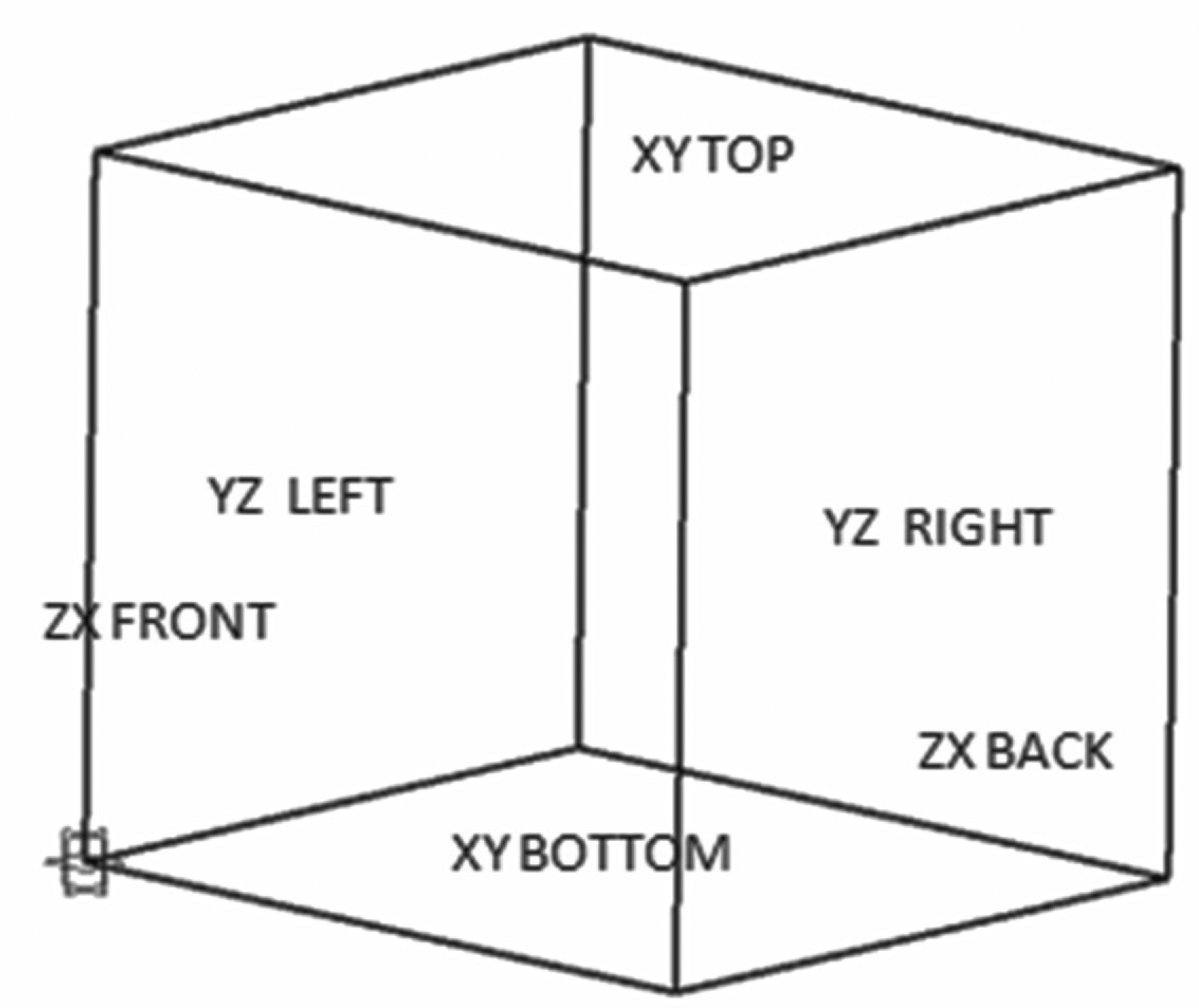
Setup plans.
Case study
The 3D part model is illustrated in Figure 7. The part geometric information is extracted from STEP AP 203 file using object-oriented technique. In all, 161 faces are extracted in geometric information file along with their loops, edges, vertices, and face directions. A total of 145 feature faces are extracted and grouped along with their dimensions using extraction and dimensional algorithms. The formulated rules are then applied on the extracted data and 40 manufacturing features are successfully recognized along with their dimensions as listed in Table 3. The process parameters such as machining operation, cutting tool, and machine tool are then defined, each feature using machining database. An algorithm is then developed based on feature location to generate the setup plan for each feature. The CAPP output is generated automatically as presented in Table 4 for the progressive die component.
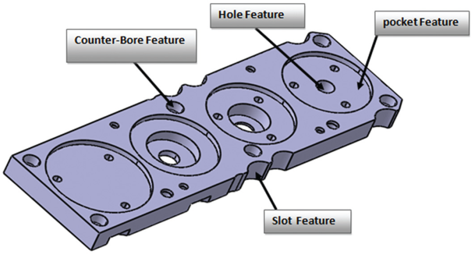
Case study component.
Feature data.

CAPP data.

CAPP: computer-aided process planning; TAD: tool access direction.
Conclusion
The methodology presented in the article is successfully tested on the progressive die component. The proposed methodology is implemented using Visual Basic that interacts with the existing CAD packages. The significance of using Visual Basic is to create a stand-alone system for CAPP. All the relevant geometrical data are extracted from STEP AP 203 file in the form of faces, loops, edges, and vertices along with their IDs. The part geometric database is created using an object-oriented technique. The output file is generated through the analysis of the geometric information available in the STEP AP 203 File. In the next step, the designed algorithms are applied on part geometrical database for automatic extraction of feature faces, establishing their geometric properties and dimensions. Afterward, the logical rules are formulated to recognize all the manufacturing features present in the part. Each feature has been given a unique feature ID. The feature data are summarized and presented in Table 3. Machining database is then created to define the machining parameters for each feature. The setup plan algorithm based on grouping of these features with respect to common TAD is applied to place each feature in a definite setup. The complete CAPP output is shown in Table 4.
The diversification of system will be improved by adding cylindrical and conical parts along with the prismatic features. In the future, the work can be extended by adding all types of die components.
Footnotes
Academic Editor: Duc T Pham
Declaration of conflicting interests
The author(s) declared no potential conflicts of interest with respect to the research, authorship, and/or publication of this article.
Funding
The author(s) disclosed receipt of the following financial support for the research, authorship, and/or publication of this article: This project was funded by the National Plan for Science, Technology and Innovation (MAARIFAH), King Abdulaziz City for Science and Technology, Kingdom of Saudi Arabia, Award Number (12-INF2816-02).