
Abstract
Conventionally, heterogeneous object modeling methods paid limited attention to the concurrent modeling of geometry design and material composition distribution. Procedural method was normally employed to generate the geometry first and then determine the heterogeneous material distribution, which ignores the mutual influence. Additionally, limited capability has been established about irregular material composition distribution modeling with strong local discontinuities. This article overcomes these limitations by developing the computer-aided design–computer-aided engineering associative feature-based heterogeneous object modeling method. Level set functions are applied to model the geometry within computer-aided design module, which enables complex geometry modeling. Finite element mesh is applied to store the local material compositions within computer-aided engineering module, which allows any local discontinuities. Then, the associative feature concept builds the correspondence relationship between these modules. Additionally, the level set geometry and material optimization method are developed to concurrently generate the geometry and material information which fills the contents of the computer-aided design–computer-aided engineering associative feature model. Micro-geometry is investigated as well, instead of only the local material composition. A few cases are studied to prove the effectiveness of this new heterogeneous object modeling method.
Keywords
Introduction
Heterogeneous object (HO) modeling has become an important research area in recent years because of the extensive use of composite materials.1,2 Generally, the material composition distribution (MCD) determines the physical performance of the HO, and it can be divided into two categories: the continuously varying MCD and the irregular MCD. For the former, the continuous variations are normally represented by certain analytical functions, which make the modeling scheme relatively simple. The commonly applied multi-material distribution and functionally graded material (FGM) distribution belong to this category. For the latter, it is nontrivial to be represented by analytical functions because of the many local discontinuities. Limited capability has been established about irregular MCD modeling. To overcome this limitation, this article contributes a computer-aided design (CAD)–computer-aided engineering (CAE) associative feature-based HO modeling method. It employs some superior characteristics compared to the existing methods, and detailed comparisons will be presented in section “Literature review.”
The following content is organized as: section “Literature review” summarizes the existing HO modeling methods and presents some comparative discussions. Section “CAD-CAE associative feature model” introduces the CAD-CAE associative feature model in detail. Section “Level set geometry and material optimization” presents the development and application of level set geometry and material optimization method in generating the geometry and material information. Two cases are studied in section “Case study” to prove the effectiveness of this new HO modeling method. Finally, conclusions are given.
Literature review
As reviewed by Kou and Tan, 3 extensive research works have been performed in the past two decades, and a brief review of the existing HO modeling methods is presented below. Voxel-based models4–6 discretize the geometry into voxels and then impose constant or continuously varying material compositions on each voxel. It is capable of capturing irregular MCD and may be directly used by finite element analysis.
Cellular model is an alternative of the geometry discretization which belongs to a bigger scale. Kumar and Dutta 7 and Kumar et al. 8 applied the r-set to model the geometry and divided it into subregions, each of which was mapped with certain MCD function. Later, Shin and Dutta 9 and Shin et al. 10 presented a constructive representation of HOs by manipulating the heterogeneous primitives with heterogeneous Boolean operations. For cellular model, the MCD function is mandatory for each cell.
Control feature-based model, developed by Siu and Tan, 11 employed the source profile feature as reference and arranged the MCD according to the source-based distribution function. This method was successfully applied to model FGM objects and composite laminates. 12 Later, the heterogeneous feature tree including multilevel source profile features and the nonregular Boolean operations were applied for compound HO modeling.13,14 Liu et al. 15 realized the local composition control by employing the single-control feature, multi-control feature, and Laplace equation-based approaches, respectively. Biswas et al. 16 proposed the distance field-based method which in nature is an extension of the control feature-based method using the implicit source profiles. It enables HO modeling of complex topologies and even starts with point cloud. 17 Recently, Gupta and Tandon 18 developed a convolution material primitive-based method for compound MCD modeling. Given the finite element analysis, You et al. 19 contributed an adaptive meshing strategy based on the control feature-based HO model.
B-spline-based model can be regarded as an extension of the control feature-based model. Qian and Dutta20,21 proposed a feature-based approach for HO modeling, in which the form and material features were separately defined; the diffusion-based B-spline method was applied to determine the MCD. Yang and Qian 22 applied the B-spline finite element method to unify the design and analysis model; the heterogeneous lofting algorithms were used to determine the MCD between B-spline material profiles. Samanta and Koc 23 optimized the B-spline-based HO model of which the MCD was determined through blending between material directrices. 24 Other HO models such as the stochastic Vironoi diagram and B-spline representation25,26 and the radial basis function-based representation 27 are also powerful in HO modeling given certain scenarios.
However, the existing HO modeling methods have limitations in the following aspects:
The majority of these methods focus on continuously varying MCD, while the modeling capability of irregular MCD is still not well developed. 3 Taking fiber reinforcement for example, Siu and Tan 12 applied the control feature-based method to model composite laminates, and composite laminates employ continuously varying fiber orientation distribution. However, for fiber-reinforced injection molding, there are many local discontinuities of the fiber orientation distribution, which cannot be properly modeled by the control feature-based method.
The majority of these methods only support the modeling of simple geometries, 18 such as the form feature-based geometry models. This severely limits the application scope.
The current methods are developed mainly for additive manufacturing, which belongs to a narrowed scope. Actually, there are plenty of HOs produced by other manufacturing methods such as injection molding and braiding.
Rarely is the focus on how to concurrently generate the geometry and material information.
This article proposes the following methodology. Level set model28,29 is a relatively novel HO representation. To be specific, each level set function is a close contour which represents the material–material (or material–void) interface. Because of overlapping, n level set functions can represent 2 n material phases, which make it suitable to model multi-material objects. Recently, the level set method was also applied to represent and optimize FGM objects, 30 in which fixed finite element mesh is used to discretize the design domain and store the local material composition information. Although the work 30 targets FGM objects, it has demonstrated the potential of modeling irregular MCD. Prominently, it also offers an optimization approach to design the irregular MCD without relying on analytical functions or control features.
Therefore, in this article, the authors propose a new HO model—the CAD-CAE associative feature model. This new HO model stores the geometry and material information separately: the geometry feature model is built in the CAD module using level set functions, while the material feature model depends on the finite element mesh. By adopting the associative feature concept, these two feature models are tightly bonded for complete information representation. Then, by developing the level set geometry and material optimization method, it enables the concurrent and optimal generation of the geometry and material information regardless of the complexity. Therefore, this new HO model is general in modeling the continuously varying and irregular MCDs, as well as complex geometry.
The CAD-CAE associative feature model is different from the voxel-based model because the geometry and material information are simultaneously generated and independently stored, instead of generating the geometry first and then making the discretization and filling in with material information of the voxel-based modeling method. However, the model is also beyond the conventional level set model. Instead of only considering local material composition, the micro-geometry has also been computationally involved by extending the level set topology optimization method into the two-scale level set geometry and material optimization method. It is more general for HO modeling. In summary, this new HO modeling method fixes the aforementioned limitations.
CAD-CAE associative feature model
For homogeneous object modeling, CAD tools are indispensable to model and manipulate complex geometries. However, CAD tools cannot record the local material compositions. But CAE tools discrete the geometry, which enables the expression of local material compositions. However, it lacks the capability of geometry manipulation. Therefore, CAD and CAE tools in combination can realize the complete HO modeling. Accordingly, the authors propose the CAD-CAE associative feature concept for HO modeling. It makes full use of the capabilities of both CAD and CAE tools and builds the tight connection in-between. An example is shown in Figure 1, where the CAD-CAE associative feature model unifies the geometry feature model from CAD module and the material feature model from CAE module through space correspondence.

CAD-CAE associative feature model.
This new feature type is developed based on the associative feature concept. The associative feature concept was initially proposed to build and manage the in-component or in-assembly semantic associations among geometry entities.31,32 Later, it is extended to sustain the design consistency of the same model across different engineering modules. 33 The CAD-CAE associative feature belongs to the latter scheme.
Geometry feature modeling in CAD
To support the geometry feature modeling, boundary representation (B-rep) is widely applied by CAD tools, which represents the solid geometry through explicit boundary entities and the related topology structure. However, in this article, structural optimization is involved as a critical procedure, for which constructive solid geometry (CSG) is more suitable because it employs the implicit boundary representation which is not sensitive to shape and topological changes, 34 and it could easily predict the elements to be solid or void.
To be specific, the level set function35,36 has been applied to implicitly represent the geometry feature primitives, which is defined as

For instance, circle feature can be modeled by

and square feature 37 by

in which (
Then, complex geometry feature model can be constructed by Boolean operations on the individual feature primitives 37 as

Finally, the geometry feature model is formulated as

where
Material feature modeling in CAE
In CAE module, the finite element mesh is used to store the local material information which naturally forms the material feature model. In this work, the fixed hexahedral mesh is used for the sake of simplicity.38,39 Extension to other mesh types is trivial.
Normally, the finite element mesh conforms to the CAD geometry which belongs to static correspondence. Differently in this article, the mesh covers the CAD geometry in bigger spatial scale. Mapping mechanism has been developed to associate the geometry feature model and the material feature model. In this way, re-meshing is avoided when optimization activities dynamically change the geometry.
Because of the inconformity, it is important to accurately map the local material information into the solid geometry domain, which could be done by applying the Heaviside function. As shown in equation (6), the grid nodes inside the geometry employ the level set values bigger than zero, and therefore, the Heaviside function is equal to 1. However, the grid nodes outside the geometry employ the level set values smaller than zero, and therefore, the Heaviside function is equal to 0

Through standard interpolation, the boundary elements can be represented by

with which the level set function can clearly predict the elements inside the geometry and approximate the elements crossed by the boundary. However, the explicit Heaviside function lacks continuity and accuracy in reflecting the boundary element properties. Therefore, the approximated Heaviside functions29,38 are normally applied.
Base material unit of the material feature model
As mentioned in the “Introduction” section, a mature HO modeling method should be generally applicable to irregular MCD, complex geometry, and diversified manufacturing methods. The former two have been realized by developing the CAD-CAE associative feature model. For the latter, it is less focused by existing HO modeling methods. For a specific manufacturing method, the generated local heterogeneity maps certain micro-geometry of the base material unit. Parameters describing the micro-geometry should be recorded instead of only the local material composition. A few base material unit types related to different manufacturing methods are summarized in Table 1, and a review can be found in a recent work. 40
A few base material unit types.

For homogeneous base material unit, its physical properties could be easily determined as there is no variable. However, for heterogeneous base material unit, its physical properties are strongly dependent on the variables, for example, the micro-geometry parameters, which are nontrivial to be directly measured. Therefore, the homogenization theory41,42 is introduced to overcome the difficulty by replacing the heterogeneous materials by equivalent homogeneous material.
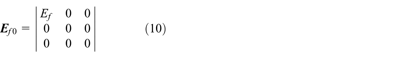
An example is given here about the elasticity tensor derivation for two-dimensional (2D) fiber reinforcement. Based on the homogenization theory, the homogenized elasticity tensor of 2D fiber-reinforced material could be determined43,44 as

where

Fiber-reinforced base material unit: (a) fiber orientation in x-direction and (b) arbitrary fiber orientation.
Specifically,

Concerning the flexibility of the fiber orientation as shown in Figure 2(b), the transformation tensor

Therefore, the elasticity tensor of fiber is transformed into

Consequently, the elasticity tensor of the fiber-reinforced material is finalized as

In this example, there are only two variables: the fiber orientation
Figure 3 shows the micro-geometry of the basic material unit, in which the dark part is filled with homogeneous material of Young’s modulus of 1.3 and Poisson’s ratio of 0.4. There is one micro-geometry parameter d designated as the variable.
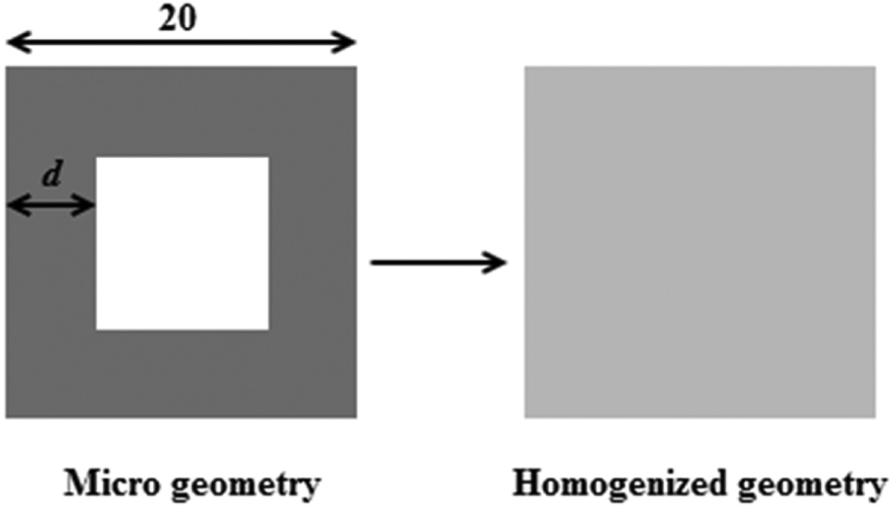
Homogenization of the micro-geometry.
As shown in equation (14), the homogenized elasticity tensor employs three independent components as


Response surface models of the homogenized elasticity tensor components: (a) E 11, (b) E 33, and (c) E 12.
Level set geometry and material optimization
After introducing the CAD-CAE associative feature concept, this section focuses on information generation through the level set geometry and material optimization. Conventionally, there are well-established theoretical basis supporting the geometry and material optimization, such as solid isotropic material penalization (SIMP),46,47 discrete material optimization (DMO),45,48 and evolutionary structural optimization (ESO). 49 However, in this article, the level set geometry and material optimization method are developed because level set functions could be the basis of CAD modeling, and the level set method addresses all sizing, shape, and topology optimization problems.
So far, the level set method is mainly used to design multi-material objects28,29 and FGM objects. 30 In this work, the authors intend to extend its capability to two-scale optimization involving micro-geometry.
The general level set geometry and material optimization problem is formulated as
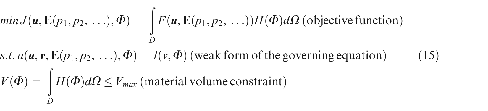
in which
This is a multi-scale optimization problem; sensitivity analysis and design update are performed not only on the level set function
The general procedures of solving this optimization problem are presented below:
Initialize the level set function based on the input geometry.
Construct the homogenized constitutive tensor of the basic material unit through homogenization method and response surface modeling. Assign initial values to the local material variables.
Configure the Lagrange formulation of the optimization problems as

in which
Perform finite element analysis to evaluate the state variable
Conduct the adjoint sensitivity analysis on the level set function

in which G is called shape gradient density and
According to the Hamilton–Jacobi equation as equation (18)

the sensitivity result is changed into

in which
Then, by defining

Conduct sensitivity analysis on local material variables
Perform design update on the level set function by solving the Hamilton–Jacobi equation. The geometry is correspondingly updated.
Perform design update on the local material variables through equation (21)

Check termination condition. If not satisfied, update the Lagrange multiplier and go back to step 4.
For more details about this procedure, see Wang et al. 38 and Allaire et al. 39
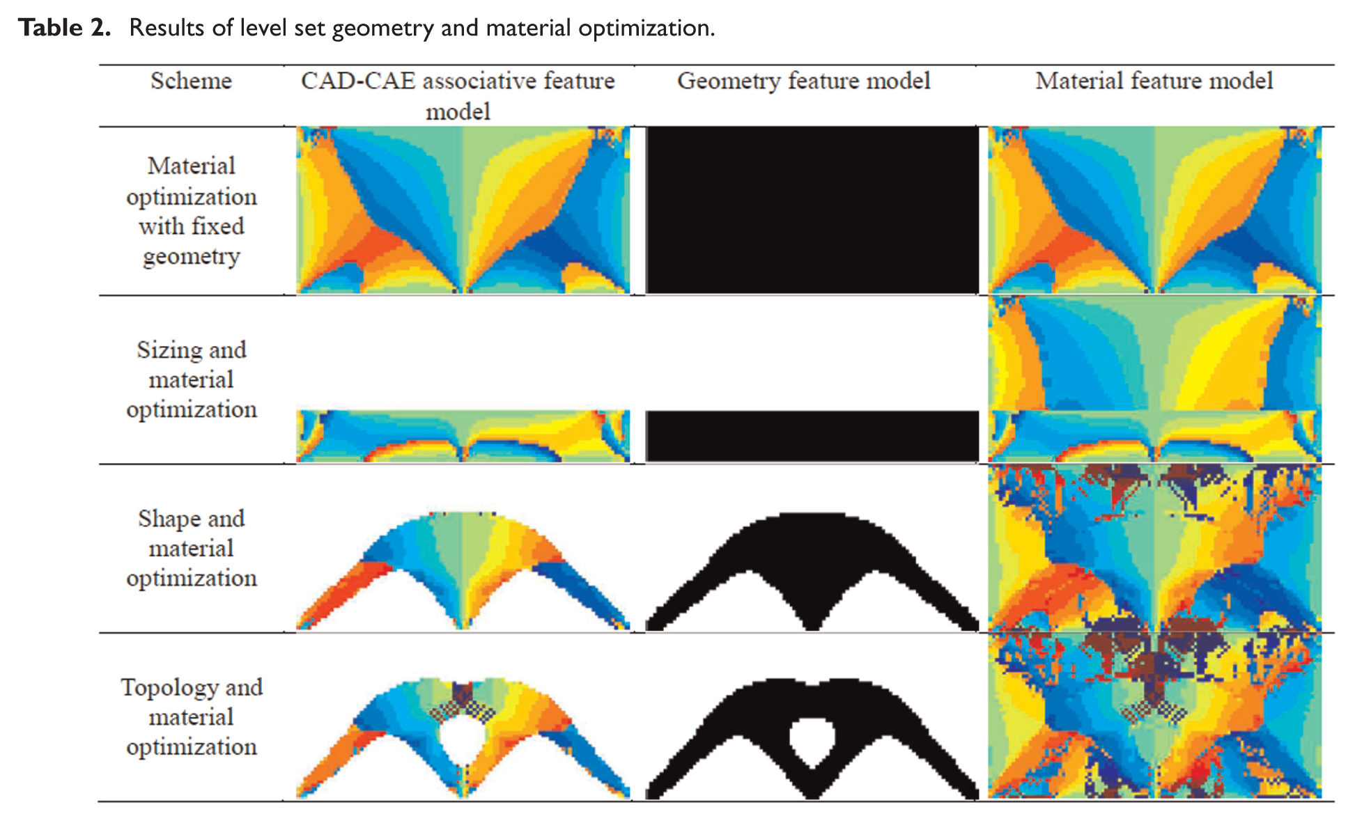
An example is presented in Figure 5, which is a fiber-reinforced Michell structure design problem. The two bottom corners are fixed and a unit force pointing downward is loaded in the bottom center. The optimization objective is to minimize the compliance under the maximum material volume ratio of 0.3. Four schemes have been defined: material optimization with fixed geometry, sizing and material optimization, shape and material optimization, and topology and material optimization. Correspondingly, the results are shown in Table 2. In Figure 5, the color bar represents the local fiber orientation from 0° to 180°, and it is shared by the figures in Table 2.
Results of level set geometry and material optimization.

Fiber-reinforced Michell structure problem.
Case study
Case 1: Michell structure design with micro-geometry
In this case, the problem setups, as shown in Figure 5, are reused, and differently, the micro-geometry depicted in Figure 3 is applied instead of fiber reinforcement. To generate the CAD-CAE associative feature model, the four different schemes of material optimization with fixed geometry, sizing and material optimization, shape and material optimization, and topology and material optimization are investigated, respectively.
The optimization results are presented in Figures 6–9. In these figures, the color bar represents the d values from 0 to 10.

Results of the material optimization with fixed geometry: (a) CAD-CAE associative feature model, (b) geometry feature model, (c) material feature model, and (d) convergence history.

Results of the sizing and material optimization: (a) CAD-CAE associative feature model, (b) geometry feature model, (c) material feature model, and (d) convergence history.

Results of the shape and material optimization: (a) CAD-CAE associative feature model, (b) geometry feature model, (c) material feature model, and (d) convergence history.

Results of the topology and material optimization: (a) CAD-CAE associative feature model, (b) geometry feature model, (c) material feature model, and (d) convergence history.
Case 2: bone adaption modeling
In order to model the bone adaption, the rank 2–layered material,42,50 as shown in Figure 10, is used as the basic material unit. The rank 2–layered material is composed of two layers of different materials: the strong material (shown in black in Figure 10) employs Young’s modulus of 2.5 and Poisson’s ratios of 0.3, and the single-rib width
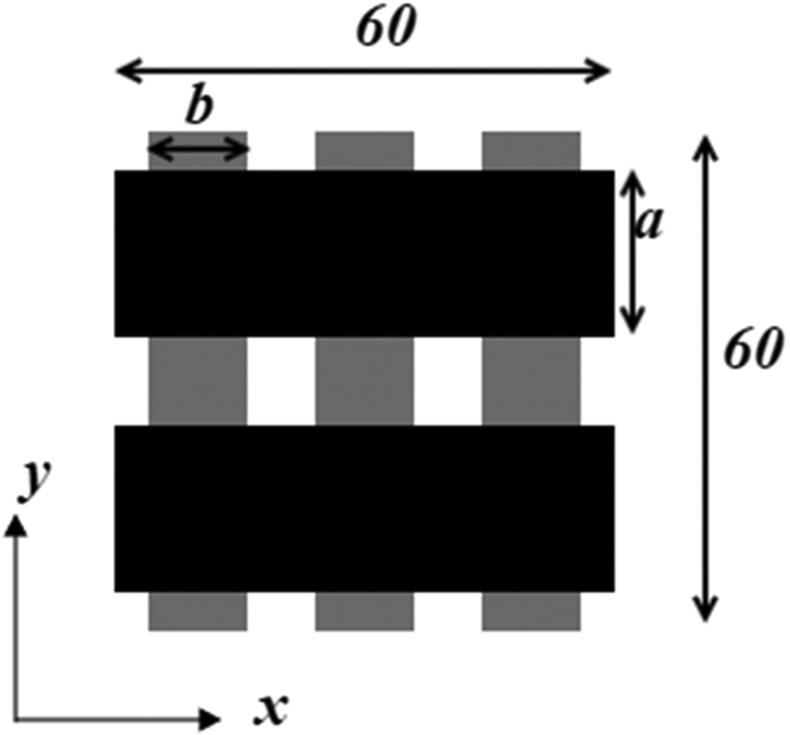
Rank 2–layered material.
Concerning the homogenized elasticity tensor, there are four independent variables, as shown in equation (14) (
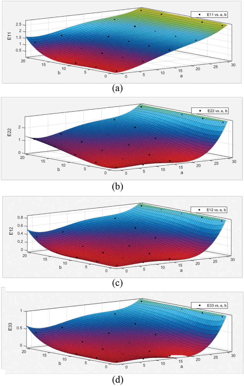
Quadratic response surfaces of the elasticity tensor components: (a) E 11, (b) E 22, (c) E 12, and (d) E 33.
Once the homogenized elasticity tensor is obtained, the material optimization with fixed geometry is performed to simulate the bone adaption process and generate the CAD-CAE associative feature model. Three different micro-geometry parameters (
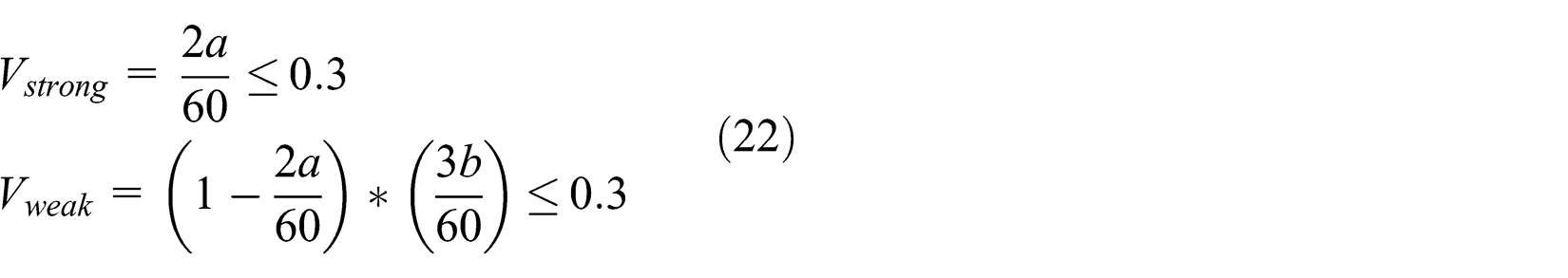
The bone geometry feature model and the boundary conditions are demonstrated in Figure 12(a). The material optimization objective is to minimize the compliance under the maximum volume ratio of 0.3 for both the strong and weak materials as presented in equation (22)

Results of the material optimization with fixed geometry: (a) the geometry feature model and the boundary conditions, (b) material feature model: the orientation distribution view (color bar: material orientation), (c) material feature model: distribution of the variable a (color bar: value of a), and (d) material feature model: distribution of the variable b (color bar: value of b).
The optimization results are presented in Figure 12(b)–(d).
Discussions
By analyzing the results presented in sections “Case 1: Michell structure design with micro-geometry” and “Case 2: bone adaption modeling,” it can be observed that all geometry feature models, material feature models, and CAD-CAE associative feature models can be effectively generated regardless of the optimization schemes. Additionally, even though the micro-geometry variable varies continuously in these results, it is nearly impossible to represent these variations by analytical functions, which means the inapplicability of the existing cellular and control feature-based models. This fact demonstrates the broader HO modeling capability of our new method. Additionally, the bone adaption results coincide with the previous work, 50 which proves the design quality.
Conclusion
This article presents a new feature type, named CAD-CAE associative feature, for HO modeling. It makes full use of the geometry manipulation capability of CAD and the local material information expression of CAE to completely construct the HO models, especially for complex geometry and irregular MCD. The application is not limited to additive manufacturing; instead, some conventional manufacturing methods are also covered.
However, generation of the CAD-CAE associative feature model is emphasized. Previously, level set topology optimization mainly optimizes homogeneous, multi-material and FGM objects. In this article, it is extended to the two-scale level set geometry and material optimization, and micro-geometry is computationally involved as well. It is more general for HO modeling.
For future work, a prototyping system is to be developed in order to conveniently implement the CAD-CAE associative feature-based HO modeling method. To make the system really working, substantial knowledge about different base material unit types should be collected to form a library, and manufacturing-oriented constraints should be reflected in the HO modeling process.
Footnotes
Appendix 1
Academic Editor: Michal Kuciej
Declaration of conflicting interests
The author(s) declared no potential conflicts of interest with respect to the research, authorship, and/or publication of this article.
Funding
The author(s) disclosed receipt of the following financial support for the research, authorship, and/or publication of this article: China Scholarship Council provided grant for their PhD student, NSERC (Canada) provided discovery grants, and MITACS and Canada Pump and Power Pte provided the accelerate cluster internship support. All the research works were carried out at University of Alberta.