
Abstract
The dynamics and vibrations of camshaft excited by multi-follower elements are modeled and analyzed. A pushrod valve train system from a four-cylinder diesel engine is selected as the case study. The camshaft is modeled to analyze the interactions of multi-follower elements. Both the camshaft angular vibration and bending vibration are taken into consideration. Each follower element is simplified as a multi-mass system. The lumped masses are connected by the spring elements and the damping elements. The contact force model at the cam–tappet interfaces was developed based on the elasto-hydrodynamic lubrication theory of finite line conjunction. From the analysis results, it can be seen that the bending vibration of camshaft is mainly in the normal direction at the cam–tappet interfaces. Moreover, the bending vibration is mainly influenced by the overlapping of inlet cam function and exhaust cam function of each cylinder. The angular vibration of camshaft mainly focuses at the fundamental frequency and the harmonic frequency corresponding to the cylinder number.
Introduction
Cam mechanism has been a very effective control mode of the synchronous motion in the engine valve trains. The follower elements are driven and controlled by the camshaft. Thus, the timing mechanism of the engine is kept by the camshaft. However, the valve spring, even the whole follower element, can vibrate at a high rotating speed. In this case, dynamic loads will be applied on the camshaft in the normal direction at the cam–tappet contact surfaces. At the same time, a friction force is also induced in the tangential direction. Moreover, both the two contact forces can produce torsions on the camshaft as the contact point shifting from one side to the other. As a result, the camshaft may work not only in the bending vibration but also in the angular vibration. The valve train of a single-cylinder engine contains an inlet cam and an exhaust cam. So the camshaft can be designed very short and its vibration can be neglected. But as for the multi-cylinder engine, the valve train is composed of multi-follower elements. Thus, a long camshaft is required to ensure the timing mechanism of all the cylinders. In this case, the camshaft will be subjected to more groups of the dynamic forces and torsions. The resulting vibration of the camshaft can deflect the follower components from their original dynamic motions, reduce the power performance of the diesel engine, and increase the noise radiation.
The dynamic behaviors of the valve train system are affected by the mass, the stiffness, and the distribution of the components. In order to reduce the vibration of the valve train system, the components are designed with light weight and high stiffness. As for the camshaft, it can be designed as hollow. Compared with the conventional solid camshaft, the hollow camshaft provides opportunities for weight reduction exceeding 60%. 1 In order to assess the vibration behavior of the camshaft, some fundamental investigations should be made, such as the natural frequency identification. Tuckmantel et al. 2 analyzed the natural frequencies and the mode shapes for the free shaft and for the fixed bearing condition.
In order to obtain the loads on the camshaft, a dynamic analysis of the cam follower mechanism is needed. And the camshaft flexibility should be taken into consideration. Koster 3 developed a dynamic model of a flexible follower driven by a flexible shaft, in which the dynamic response was characterized by merely two dimensionless parameters, one for the follower and other for the camshaft. Teodorescu et al. 4 presented an analysis of a line of valve trains from a four-cylinder diesel engine. In the research, the bending vibration model and the angular vibration model of the camshaft were built by spring elements and damping elements. Kushwaha et al. 5 studied the effect of camshaft flexibility on valve train dynamics. In this way, the camshaft is modeled by two inertial point masses, connected by a three-dimensional (3D) elastic field, represented by a stiffness and a damping matrix. Isaac Du and Chen 6 developed a 3D dynamic model to investigate the dynamic response of a finger-follower cam system by considering the interaction between valve train and camshaft. The results showed that the resulting speed fluctuations of the cam affect the dynamics of other valve train components including the ultimate valve motion. Rivola et al. 7 developed a combined lumped/finite element model of a desmodromic valve train system from a racing motorbike engine. The effectiveness of his model is satisfactorily achieved. Takagishi et al. 8 developed a simulation model to predict both the timing chain load and the valve train driving torque with high accuracy and in a short time.
Simulation model
Figure 1 shows the schematics of the valve train system from a four-cylinder diesel engine. Each valve train element is composed of tappet, pushrod, rocker arm, valve spring and valve, and so on. Their motions are all controlled by a corresponding cam. So the camshaft can be considered as a key link of the different valve train elements. The rotating motion of camshaft is converted to the reciprocating motion of tappet through the cam–tappet interaction. Thus, the hydrodynamic characteristics in the contact surfaces should be highlighted.

Schematics of a multi-cylinder train system.
Bending vibration model of camshaft
The bending vibration model of the camshaft is shown in Figure 2.


where

Bending vibration model of camshaft.
Figure 3 shows the analysis of the nodal force considering two neighboring beam elements, element


Schematic of nodal forces.
The proportional damping is used to determine the damping force and moment. Similar to the elastic force and moment,
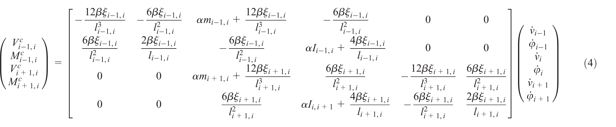
where


Using equations (4) and (5), we obtain

Equation (8) and (9) are the governing equations of the camshaft bending vibration in the


Similarly, the boundary conditions for the last node (


For the bending vibration in the


where
Angular vibration model of camshaft
The angular vibration model of the camshaft is shown in Figure 4. The nodes are also built at the position of the cam and the journal. They are in keeping with that in the bending vibration model. Any two neighboring nodes are connected using the torsional spring element and damping element. The explanations for some signs at node

Angular vibration model of camshaft.
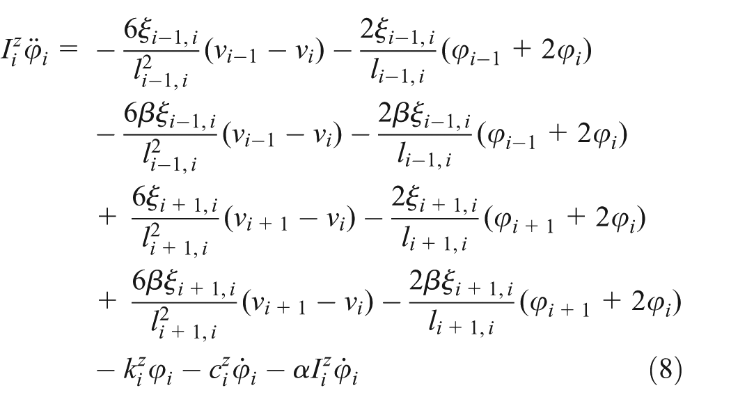
According to Newton’s second law, the angular motion of node

Equation (15) is a general expression for the angular vibration of the camshaft. If node
The bending vibration model and the angular vibration model of camshaft are used to connect different individual valve train elements. The interactions between each cam and the corresponding valve train element are established by defining the normal force, the friction force, and the transient torque in the contact surfaces.
Dynamic model of each individual valve train element
Each individual valve train element is modeled as a multi-body system, comprising a number of inertial elements connected with elements accounting for stiffness and damping. Figure 5 shows the dynamic model for an individual valve train element. In this model, the tappet is regarded as a rigid body since it is sufficiently stiff. The pushrod, rocker arm, and valve stem are all modeled as 2 degrees of freedom subsystem.

Dynamic model of an individual valve train element.
Applying Newton’s second law of motion to each lumped mass, the equations of motions can be obtained as

where

where
Considering the flexible compliance of the valve spring, it is modeled to be a distributed parameter subsystem rather than a lumped mass subsystem. The displacement of the spring element can be described by the wave equation 10

where
The displacement of the valve spring element is the sum of the static displacement plus a dynamic deviation,

Combining equations (18) and (19), the governing equation for the dynamic motion becomes

As a result, the force exerted by the spring on the valve can be obtained by

The contact stiffness values in Figure 5 are obtained from the static contact relationship between applied force and displacement following linear contact theory by using finite element method. 11 The values of damping coefficients are initially assumed to be 3%–5% of the critical damping. Under the actual operating condition, the valve train components perform repeated contacts and separations. There is no force applied on each other when two neighboring components lose contact. In this case, the contact stiffness and damping coefficients were set to be zero during the separation events.
Contact model of cam–tappet
Figure 6 shows a schematic of the cam–tappet interface. The cam to a flat tappet contact at a particular cam angle can be regarded to be a line contact condition of finite length.
12
There are two kinds of contact forces between the cam and the tappet. One is the normal force


Contact model of cam–tappet.
The boundary friction component

where

where

where

Some contact parameters are established based on the data given in the studies by Teodorescu et al. 13 and Yang et al. 14 More information about the contact model of cam and tappet can be seen in the study by Guo et al. 15
Experiment validation for a single-valve train element mechanism
One of the major problems in the modeling work is validating the theoretical models with the experimental data. In this study, the valve train model is built for a generic line of valve train elements. However, subject to the conditions, the dynamic model of only a single-valve train element is validated with the experimental results. The analysis results are shown in Figures 7–9. The curve of valve lift is predicted from the simulation, and it is used to identify the valve working phase.

Analysis of pushrod force (900 r/min).

Analysis of valve acceleration in time domain (700 r/min).

Analysis of valve acceleration in frequency domain (700 r/min).
As can be seen in Figure 7, the predicted pushrod force at 900 r/min is in reasonably agreement with the measured result. The main differences are seen in the valve closing event. The reason can be interpreted by the working mechanisms of valve train. The strain energy is stored in the elastic components when the valve is opening. After the cam nose contact, the stored strain energy will be released in the form of vibration of all the elastic components. As a result, a nonlinear vibration of the valve spring may be produced as well as an irregular movement of all the components. However, these behaviors are not considered in the simulation model. The spring model is linear and the motion or vibration of all the component models is one dimension.
The predicted valve acceleration in time domain is compared with the measured result in Figure 8. The predicted result is also in reasonably agreement with the measured result. Large fluctuations are also seen in the measured result when the valve is closing. It can also be interpreted by the behavior of the energy release. The interval marked with T is the quasi-periodic of the main signal in the valve acceleration. According to calculations, the frequency corresponding to the quasi-periodic T is 735 Hz. This is a modal frequency at which all the components of the valve train element act in an overall mode. In addition, the fundamental frequency of the camshaft rotating speed is 11.67 Hz, and the 63th harmonic frequency is nearly 735 Hz. Thus, it can be concluded that the signal of frequency 735 Hz is generated from the resonance between the valve train system mode and the corresponding harmonic. Figure 9 shows the Fourier spectrums of the valve acceleration in frequency domain. Some harmonic signals (e.g. 3th, 7th) and the signal of frequency of 735 Hz are seen both in the predicted and measured results. The components in the range of 600–900 Hz in the measured spectrum are more than those in the predicted spectrum. The reason may be that the natural properties of some components are not accurately taken into consideration in the dynamic model. In the low-frequency range, the spectrums have very similar properties compared with that of the cam acceleration. Thus, it can be concluded that the cam profile is the main factor that influences the valve train dynamics in the low-frequency range. In general, each cam function is composed of some sectional curves. So the valve train dynamics in the low-frequency range has close relationship with the sectional properties of the cam function.
Analysis of camshaft vibration
Referring back to Figure 1, a simulation study is undertaken with respect to four inlet valve train elements as well as four exhaust valve train elements. The eight-valve train elements are from a four-cylinder, four-stroke diesel engine with a cylinder firing order 1-3-4-2. The rated speed of the engine is 2200 r/min (1100 r/min for camshaft). The motions of all the valve train elements are controlled by the camshaft. Thus, the interactions between different individual valve train elements can be understood by the bending vibration and angular vibration of the camshaft. Figure 10 shows a schematic of a camshaft from a four-cylinder diesel engine. The camshaft has three journals, four inlet cams, and four exhaust cams. For convenience, each cam is given a short name. For example, the inlet cam of the second cylinder is named as In.2 cam and the exhaust cam is named as Ex.2 cam.

Schematic of a camshaft from a four-cylinder diesel engine.
The simulation results caused by a single-valve train element are shown in Figure 11. In the simulations, only the inlet valve train element of the second cylinder is controlled by the camshaft, and other valve train elements are not considered. The camshaft is excited by the normal force and the friction force in the cam–tappet interface. Combined with the curve of the cam pseudo acceleration, the normal contact force has peak values associated with the plus or minus peaks of the cam pseudo acceleration. It can be seen that the maximums of the normal contact force are directly related to the first plus phase of the cam pseudo acceleration. As a result, the curve of the normal deflection at the position of the cam has a similar shape compared with that of the normal force.

Bending vibration by one-valve train element (1100 r/min).
The lubrication characteristics in the cam–tappet contact can be interpreted by the lubrication thickness and the friction force. The curve of the lubricant film thickness is very similar to the cam pseudo acceleration. There are two obvious periods in which the lubricant is especially sufficient and has a maximum thickness of about 0.8 µm. The two periods, respectively, correspond to the two plus phases of the cam pseudo acceleration. The reason for the sufficient lubricant in the two periods is the big entraining velocity of the lubricating oil. 15 Lubricant conditions are likely to be less severe in the two periods due to the increase in the lubricant film thickness. As a result, the friction force mostly concentrates on the minus phase of the cam pseudo acceleration. Moreover, the camshaft bending deflection at the position of the working cam in the tangential direction has the same tendency. Compared with the bending deflection in the normal direction, the bending deflection in the tangential direction is very small.
The camshaft bending vibrations by two-valve train elements are analyzed in Figure 12. The upper figure shows the inlet cam lift and the exhaust cam lift. It can be seen that the two lifts are overlapping. The second figure is about the analysis of the two cam pseudo accelerations. It is obvious that the overlapping period is related to the closing acceleration maximum of the inlet cam and the opening acceleration maximum of the exhaust cam. Accordingly, the maximums of the two cam forces will meet each other coincided. The camshaft bending deflections at the positions of In. 2 cam and Ex.2 cam are shown in the lower part of Figure 12. It can found that the maximum of the cam bending deflection is added due to the force overlapping. The bending defections along the whole camshaft because of the force overlapping are shown in Figure 13. The force overlapping adds a camshaft bending deflection of 4.2 µm. Combined with Figure 11, the value is very close to that of the lubrication thickness in the cam–tappet contact. In this case, the lubrication condition between cam and tappet will be influenced.

Bending vibration by two-valve train elements (1100 r/min).

Bending vibration by one- and two-valve train elements (1100 r/min).
The camshaft angular vibration by two-valve train elements is analyzed in Figure 14. The analysis in the lower part is for the position of the inlet cam. The two consecutive fluctuations are caused by the inlet cam torsion and the exhaust cam torsion, respectively. They are nearly the same. This means that the effect of the neighboring cam torsion on a cam is equivalent to that of its own torsion. It can also be seen that the two cam torsions are overlapping. Unlike the bending vibration, the directions of the two cam torsions are exactly different in the overlapping period. As a result, the angular vibration of the camshaft is not increased by the overlapping of the inlet cam torsion and the exhaust cam torsion.
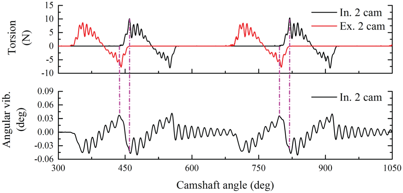
Angular vibrations by two-valve train elements (1100 r/min).
The camshaft vibration will become more complicated when all the valve train elements are working in the control of camshaft. Figure 15 shows the analysis of the camshaft bending vibration caused by eight-valve train elements. The cylinder firing order is 1-3-4-2. All the overlappings of inlet cam lift and exhaust cam lift of each cylinder are highlighted in a working cycle. It can be seen that the values of the camshaft bending deflections are added by all the overlappings of the cam functions. Moreover, the maximum of the bending deflections corresponds to the overlapping to the second cylinder. The reason can be found in the upper part of Figure 15. When the overlapping to the second cylinder is produced, Ex.1 cam is in working state. In this case, a dynamic force will be applied on the Ex.1 cam. Combined with Figure 10, the Ex.1 cam is next to the In.2 cam, and there is no bearing between them. In other words, the bending deflections added by the overlapping to the second cylinder are also increased by the Ex.1 cam force.

Bending vibration by eight-valve train elements (900 r/min).
The angular vibration of the camshaft excited by eight-valve train elements is analyzed in Figure 16. In the simulations, the input end of the camshaft rotates at an invariable speed. The input end of the camshaft is taken as reference to discuss the angular vibrations at the positions of all the cams. It can be seen that the angular vibrations at the positions of all the cams are at the same frequencies, and which are different are the amplitudes. The more distant the position, the bigger it vibrates. The maximum of the angular vibration is produced by the overlapping of In.3 cam torsion and Ex.4 cam torsion. Combined with the bending vibration in Figure 15, it can also be seen that the angular vibration shows exactly a different level. That is to say, when the camshaft is in a bigger angular vibration, the bending vibration is relatively smaller.

Angular vibration by eight-valve train elements in time domain (700 r/min).
Two main signals can be seen in Figure 16. Suppose the quasi-periodic of the two signals are
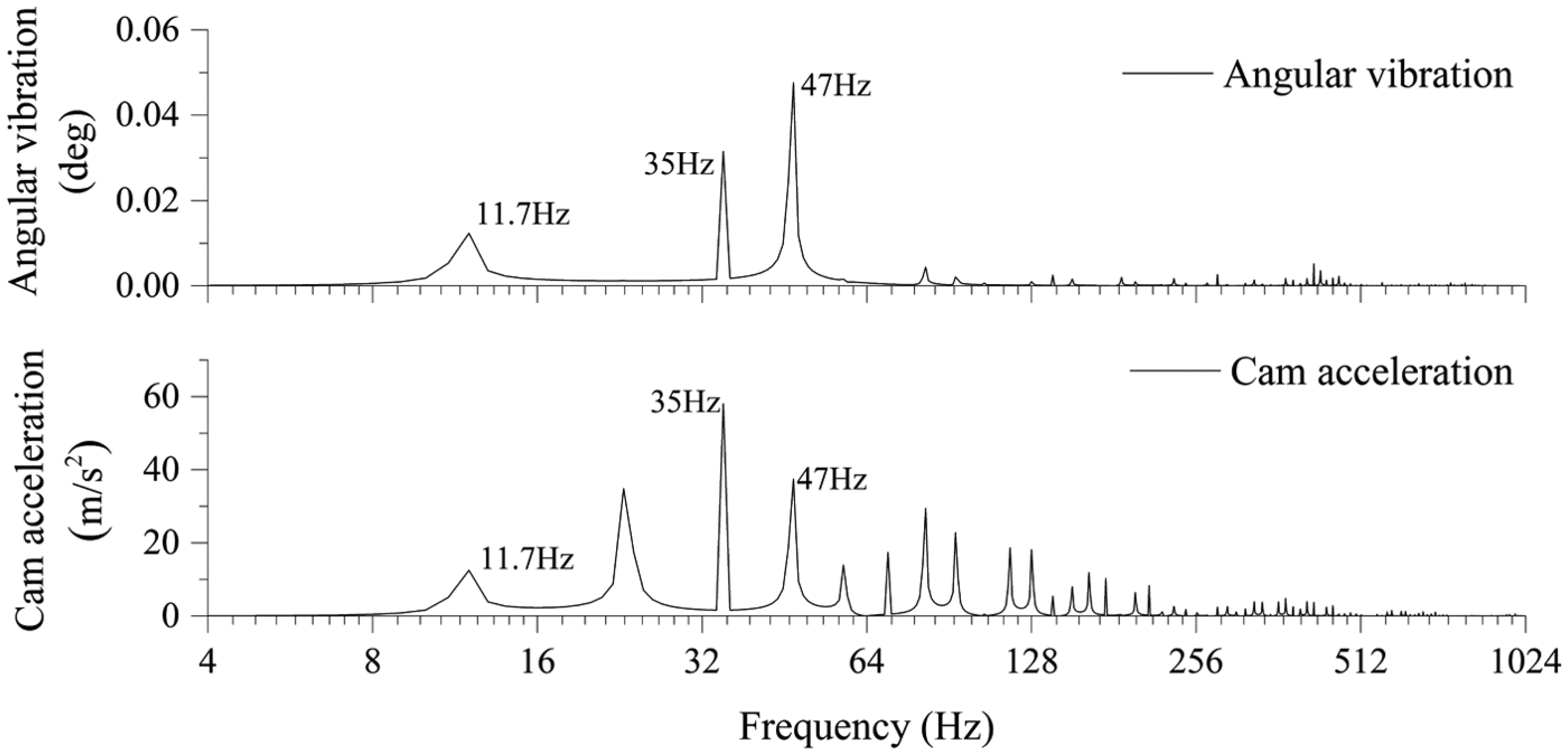
Angular vibration by eight-valve train elements in frequency domain (700 r/min).
Conclusion
A dynamic model of valve train in multi-cylinder diesel engine is developed to analyze the dynamics and vibrations of the camshaft. In the model, both the angular vibration and bending vibration of the camshaft are taken into consideration. The analysis results show that the bending vibration of camshaft is mainly in the normal direction of the cam–tappet interfaces. Moreover, the bending vibration is mainly influenced by the overlapping of inlet cam function and exhaust cam function of each cylinder. The angular vibration of camshaft mainly focuses at the fundamental frequency and the harmonic frequency corresponding to the cylinder number.
Footnotes
Appendix 1
Academic Editor: Jose Ramon Serrano
Declaration of conflicting interests
The author(s) declared no potential conflicts of interest with respect to the research, authorship, and/or publication of this article.
Funding
The author(s) disclosed receipt of the following financial support for the research, authorship, and/or publication of this article: this work was supported by the National Natural Science Foundation of China (51405094), the Fundamental Research Funds for the Central Universities (HEUCF140305), and the China Postdoctoral Science Foundation (2014M561329).