
Abstract
The purpose of this study is to predict the front-end curvature in hot strip finishing mills and to prevent it by controlling the rolling conditions. A theoretical model based on the slab method is developed for predicting the front-end curvature by taking into account the entrance angle of the strip, the friction condition and the back tension. To validate the developed theoretical model, the theoretically obtained curvature value is compared with the results of finite element analysis. Consequently, it is shown that the calculation results of the theoretical model are in good agreement with the measured results of the finite element analysis. Furthermore, a curvature control model based on geometrical and mathematical approaches that can reduce the front-end curvature by the control of the roll speed ratio of the upper to lower rolls is proposed. The proposed curvature control model is verified by finite element analysis, and it is shown that the front-end curvature can be reduced considerably using the proposed model. Therefore, it is concluded that the proposed control model for reducing the front-end curvature in a hot strip finishing mill can be used to improve the quality of the rolled product.
Keywords
Introduction
A typical hot rolling mill consists of a reheat furnace, sizing press, roughing mill, finishing mill, runout table and coiler, as shown in Figure 1. Among these components, the finishing mill, which is composed of two work rolls (WRs), two intermediate rolls (IMRs) and two backup rolls (BURs) supporting them, has a major influence on the dimensional accuracy of the slab thickness.
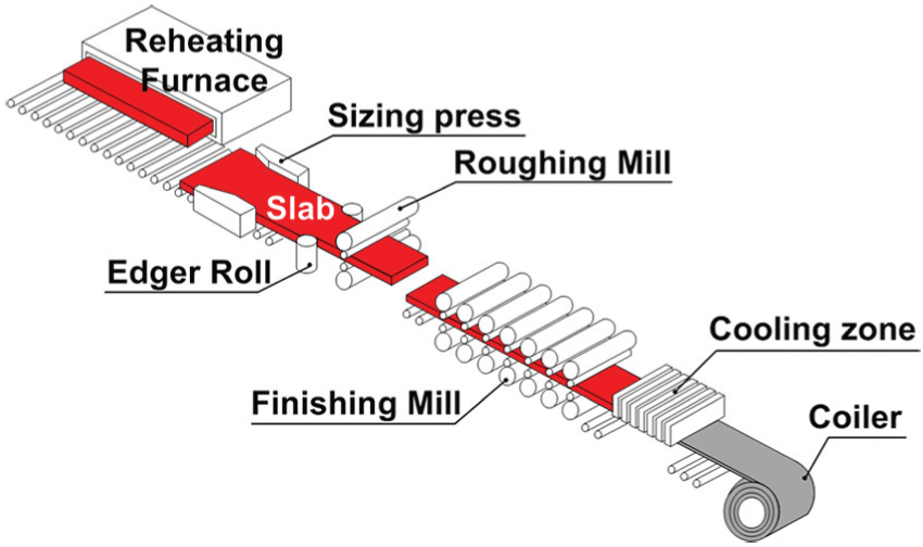
Schematic illustration of hot rolling process.
During hot finish rolling, the ideal symmetry boundary conditions between the upper and lower rolls cannot always be guaranteed because of the complex interactions between the mill stands. Various asymmetrical working conditions such as the pass schedule, differences in WR radii, angular speed differentials of the WRs, strip temperature distribution, friction, tension, looper angle and entrance angle can induce a non-uniform deformation behaviour in the deformation zone and consequently lead to a front-end curvature (FEC), that is, turn-up/down. Turn-up makes bite by the WRs in the next stand difficult, whereas turn-down causes severe damage to the rolling table. Figure 2 shows an example of FECs. 1

Front-end curvature in hot rolling process. 1
Thus far, few studies have been conducted on the effect of the asymmetric rolling factor on the rolling force, rolling torque and deformed strip shape during the hot rolling process. Hwang and Tzou 2 presented an analytical model for general asymmetrical cold rolling in order to investigate the behaviour of sheet metals during asymmetrical rolling using slab analysis. Use of this model enabled rapid determination of the rolling pressure distribution, rolling forces and rolling torques. Lu et al. 3 conducted an analytical and numerical investigation of the hot rolling process; their results showed that strip curvature may be caused by different diameters of the WRs and by the degree of reduction in the bending of the workpiece. Salimi and Sassani 4 predicted the mode of deformation in asymmetrical rolling in terms of a modified slab method through a simple and fast procedure. They compared the development of strip curvatures due to a speed mismatch with the experimental values available in the literature and found good agreement between both. Salimi and Kadkhodaei 5 presented a theoretical model based on the slab method for the analysis of a plane strain asymmetrical rolling process. Their results showed that the non-uniformities of the normal and shear stresses across the section of the deforming material within the plastic region are important to be considered in the derivation of the governing equations and yield criterion. This model could successfully predict the rolling force, torque and pressure. Knight et al.6,7 simulated the hot strip rolling process using an elastic–plastic plane strain finite element (FE) model. They studied the effects of asymmetrical factors, rolling parameters and roll speed mismatch on the strip curvature. Philipp et al. 8 investigated the influences of the related mismatch of circumferential speed between the WRs, the entrance thickness of the rolling stock and the draft per pass on the front-end bending. Gudur et al. 9 presented a methodology for estimating the coefficient of friction from the asymmetric rolling process. Tian et al. 10 developed a new rolling force model and torque model based on the slab method for an asymmetrical rolling process. The plastic deformation region at the roll gap was divided into three distinct regions: the backward-slip zone, cross shear region and forward-slip zone. Gong et al. 11 investigated the effect of asymmetric friction on FEC in plate and sheet rolling processes.
The above-mentioned studies focused on the effect of asymmetrical factors such as roll speed mismatch, friction differentials and strip thickness differences on the strip curvature. However, they did not consider the influence of the entrance angle on the FEC. In the finish rolling process, loopers are installed between the stands in order to control the process stability and tension regulation. The variable looper angle affects the entrance angle of the rolling strip and consequently affects the contact lengths, contact angles between the rolls and the strip, the movement of a neutral point, the rolling force and the rolling torque.
In this study, with the aim of establishing a control model for achieving optimum rolling settings to ensure a straight strip, the slab method and finite element analysis (FEA) are used to analyse the influences of the entrance angle, friction differentials and mismatch of the WR angular speed on the FEC during the hot finish rolling process. This control model is established on the basis of the strip thickness, circumferential speed between the WRs and ratio of the upper to lower contact lengths between the WR and the strip. The developed control model is validated by conducting FE simulations using a plane strain plastic FE model. The analytical results are evaluated in terms of the vertical deflection of the rolled strips.
Theoretical model for predicting FECs
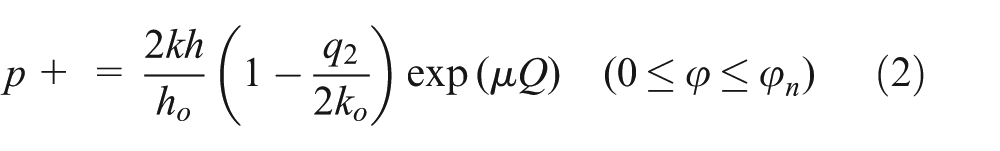
Figure 3 shows the slab model for the calculation of the rolling force of a unit element in the deformation zone. The rolling force is calculated by Bland and Ford’s equation as follows


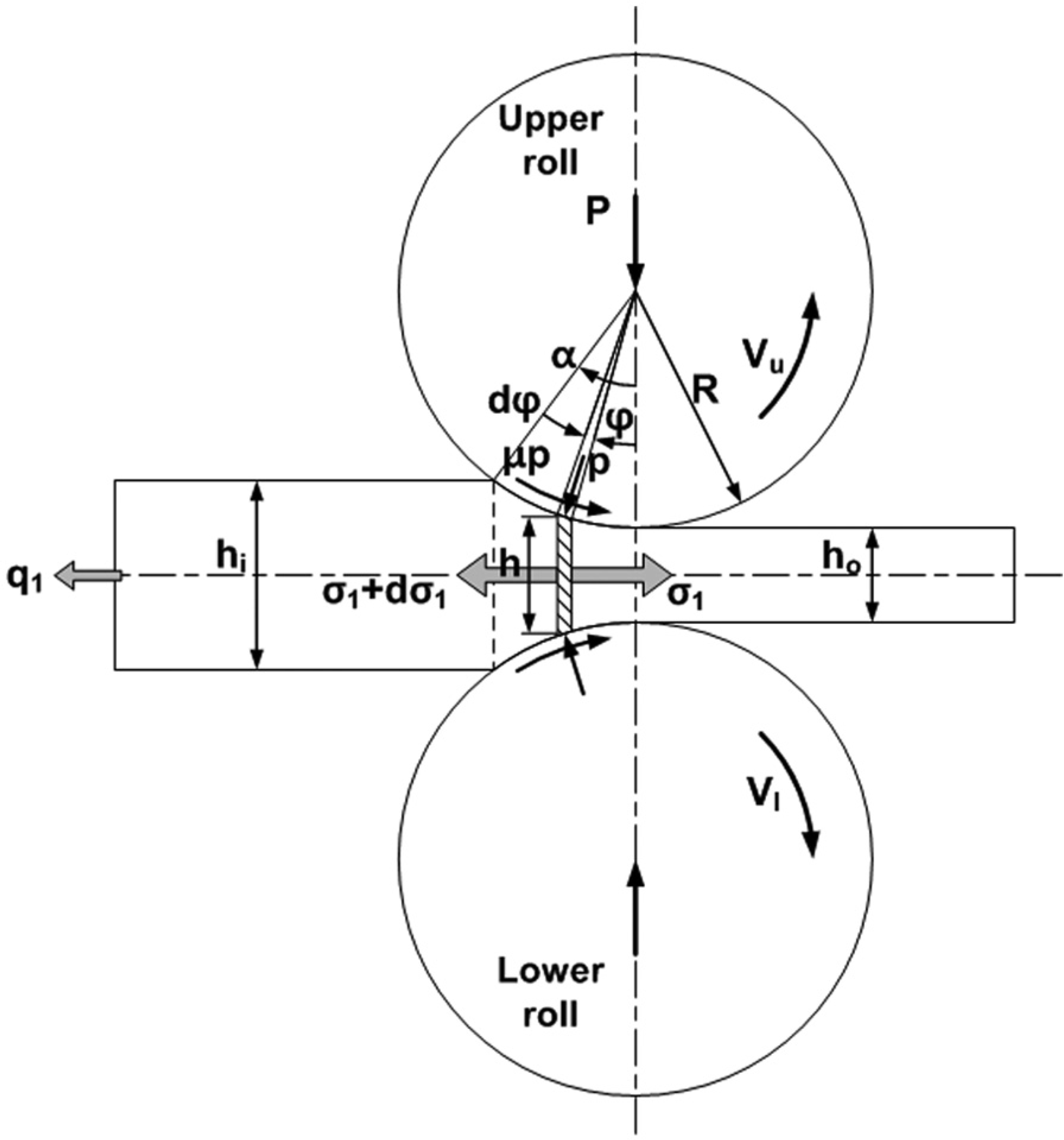
Stress state of strip rolling.
where P is the rolling force per width; R ′ is the flattening roll radius according to the Hitchcock equation; α is the roll bite angle; p is the vertical stress; ϕn is the neutral angle; k is the mean yield shear stress of the slab; hi and ho are the initial and target thicknesses, respectively; q 1 and q 2 are the back and front tensions, respectively; µ is the coefficient of friction; and ki and ko are the deformation resistances of the hot strip at the entrance and exit, respectively.
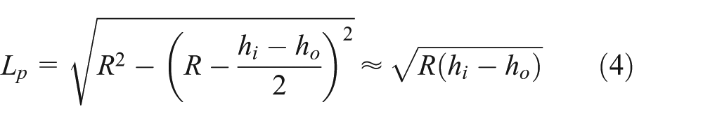
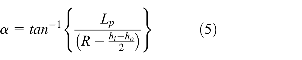
From the given geometric conditions, the projected length of the contact patch Lp between the strip and the rolls and the roll bite angle α are given as follows
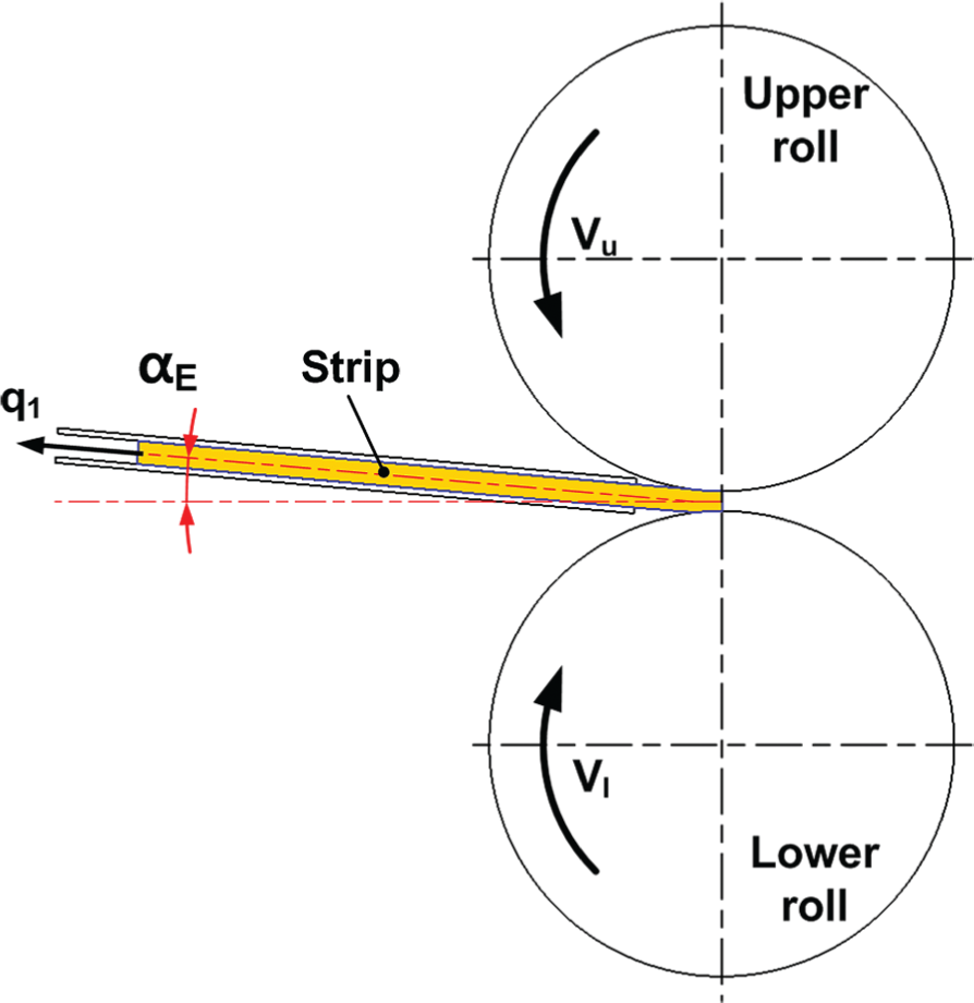
The roll bite angle α is related directly to the entrance angle αE , as shown in Figure 4. As the entrance angle increases by the upward looper motion, the roll bite angle αU between the strip and the upper WR increases and the roll bite angle αL between the strip and the lower WR decreases.

Contact angle in strip rolling with arbitrary entrance angle.
The rolling torques per unit width of the upper roll and lower roll, TU and TL , are, respectively, given by


where ϕn,U and ϕn,L are the neutral angle of the upper and lower WRs, respectively. Substituting equations (2) and (3) into equations (6) and (7) and rearranging the terms give the rolling torque as follows
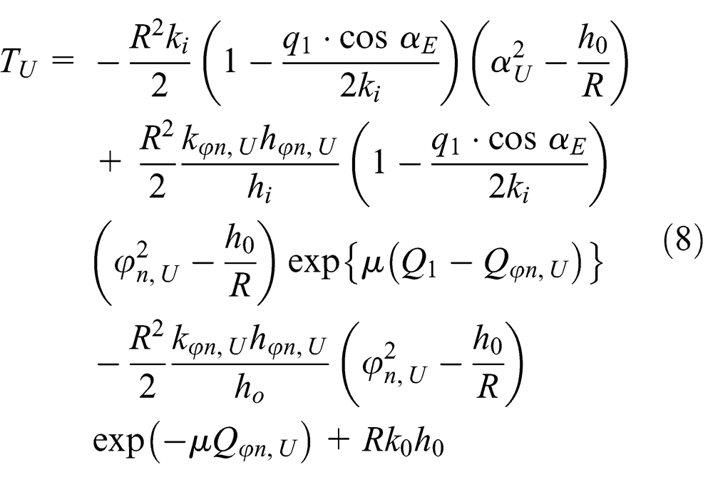
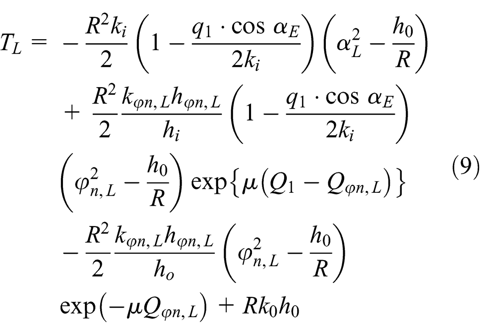
where kϕn and hϕn are the deformation resistance and thickness at the neutral angle, respectively; αE is the entrance angle; and subscripts U and L are the upper and lower WRs, respectively.
The difference in rolling torques between the upper and lower WRs leads to FEC. Therefore, the curvature of the strip is given as follows

where k is the strip curvature; ρ is the bending radius of the rolled slab; and E and I are the elastic modulus and section modulus, respectively, of the strip materials.
FEA for verifying theoretical model
FE modelling for hot finish rolling process
To investigate the proposed theoretical model further and prove its validity, we developed a two-dimensional (2D) plane strain model for the hot finish rolling process using DEFORM-2D, as shown in Figure 5. Rolling simulations were performed using a coupled thermo-mechanical tetrahedral element with four nodes. The strip material was AISI 1045 carbon steel alloy, having an elastic modulus and Poisson’s ratio of 200 GPa and 0.3, respectively. The results of hot compression tests performed under different temperatures and strain rates were used for determining the material’s stress–strain curves, as shown in Figure 6.
FE modelling of hot rolling process with arbitrary entrance angle.

Stress–strain curves of AISI 1045 under different strain rates and temperatures: (a) 800°C, (b) 900°C, (c) 1000°C, and (d) 1100°C.
The initial parameters of the rolling strip were as follows: temperature, thickness and draft of 900°C, 40 mm and 6 mm, respectively. The WRs were treated as rigid bodies; the general conditions of the simulation are listed in Table 1. The initial parameters of the WR were as follows: temperature, diameter and rotation speed of 500°C, 800 mm and 40–42 r min−1, respectively. Additionally, the ranges of the entrance angles, back tensions and friction factors were described, and thereafter, the front tension was assumed to be zero. The friction constant at the strip–WR interface was 0.2–0.6. The temperature-dependent physical properties (thermal conductivity specific heat, etc.) of the strip used here were obtained from Metal Suppliers Online of America: specific heat of 0.486 J g−1°C−1, conductivity of 24.747 W°m−1°C−1 at 799°C and 32.896 W°m−1°C−1 at 999°C and emissivity of 0.7.
Input parameters required for hot finish rolling process.

WR: work roll.
Results and discussion of FEA
A series of FE models were computed, and the corresponding results are shown in graphical form in Figures 7–9. A total of 64 models were analysed by considering different asymmetric factors and rolling parameters, according to the values listed given in Table 1.
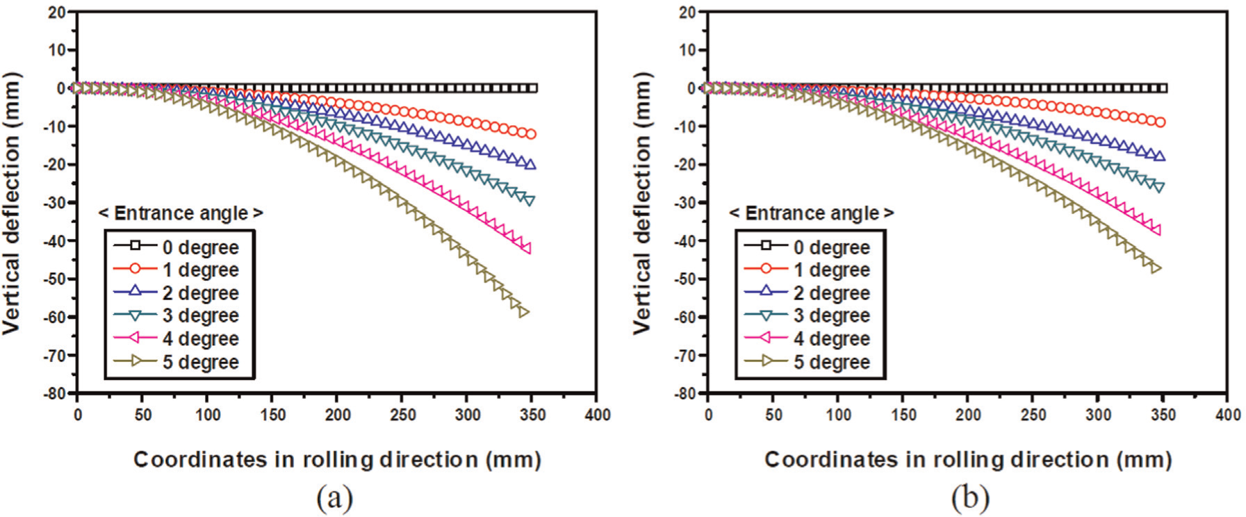
Shape of deformed strip under different entrance angles: (a) without back tension and (b) with back tension of 10 MPa.

Shape of deformed strip under different friction factors.

Shape of deformed strip under different WR angular speed ratios.
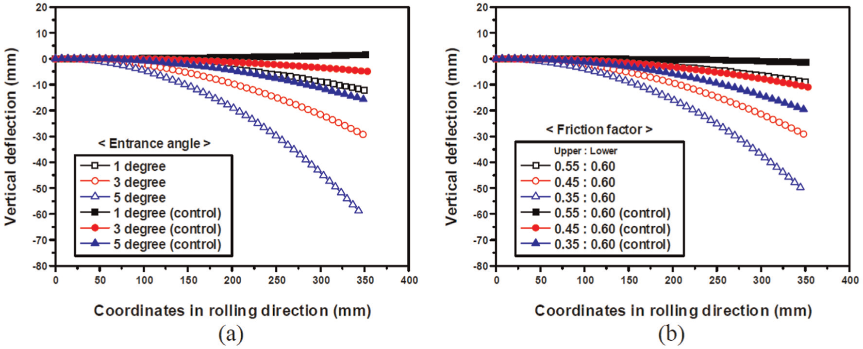
Figure 7 shows the effects of different entrance angles and back tensions on the vertical deflection, that is, the strip curvature. Entrance angles of 0°, 1°, 2°, 3°, 4° and 5° were applied to the rolling strip for back tensions of 0 and 10 MPa. A higher entrance angle always causes an increase in the FEC. An increase in back tension can reduce the difference in axial and shear strains 9 and consequently reduce vertical deflections. The maximum strip curvature occurred when the entrance angle was 5° without any back tension.
Strip curvature was measured over the first 350 mm of the strip exiting the roll gap. R was calculated by approximating the radius of curvature to the front end of the strip. The strip curvature is given by 1/R, where a positive value indicates turn-down. The effects of asymmetric factors and rolling parameters on the strip curvature are presented in Tables 2 and 3, respectively. It can be seen that the strip curvatures predicted by the theoretical model are in good agreement with the simulated ones. The percentage deviations of FEC values between the proposed model and the FEA are 5.04e−5 and 3.67e−5 in Tables 2 and 3, respectively. Thus, the results demonstrate that the proposed model for predicting FECs can work effectively for the hot finish rolling process.
Comparison of FEC values calculated using mathematical model and FEA under different entrance angles and back tensions.
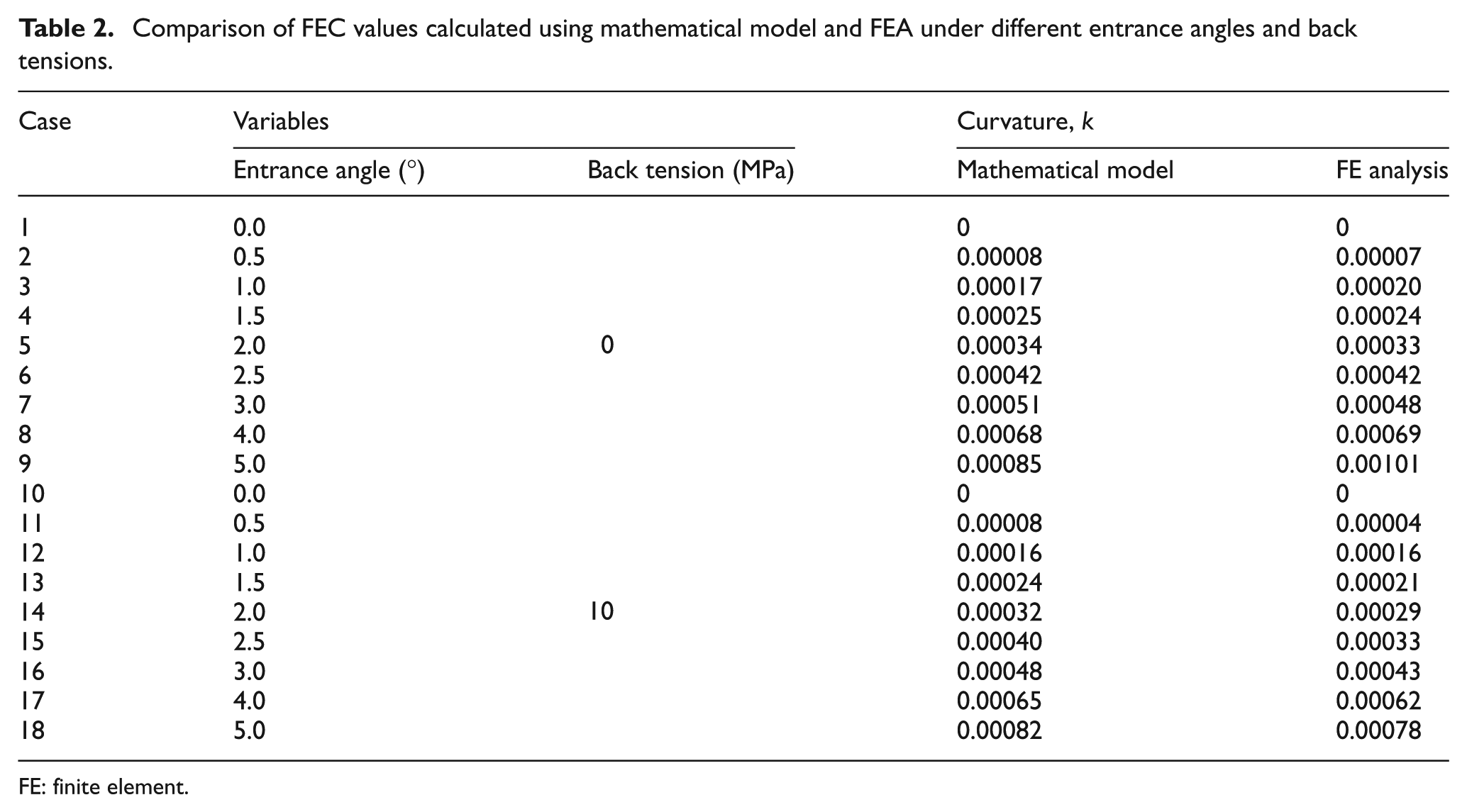
FE: finite element.
Comparison of FEC values calculated using mathematical model and FEA under different friction factors (entrance angle: 0°, back tension: 0 MPa).
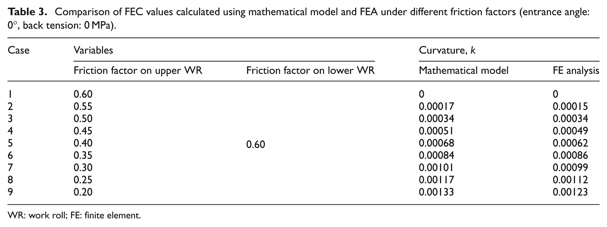
WR: work roll; FE: finite element.
Figures 8 and 9 show the amounts of vertical deflections with various friction factors and the WR angular speed ratios of the upper WR to the lower WR, respectively. Six interface frictional differences were analysed: mu /ml = 1.00, 0.92, 0.83, 0.75, 0.67 and 0.58. The vertical deflection was found to increase with increasing differential interface friction. Other analyses were performed at six different WR angular speed ratios, vu /vl = 1, 1.01, 1.02, 1.03, 1.04 and 1.05, where the upper roll had higher velocities. In all cases, the magnitude of vertical deflection increased with increasing WR angular speed ratio.
The proposed model was compared with the analytical results obtained by Pang et al. 12 as well as with the simulated results in terms of the FEC values, as shown in Figure 10. The strip curvature in all three case studies increased with increasing entrance angle. This indicates that the results of the proposed model are in better agreement with the simulated ones than with those of the reference model. The proposed model is an analytical solution that can easily and rapidly predict the characteristics of asymmetrical rolling and save computational cost.
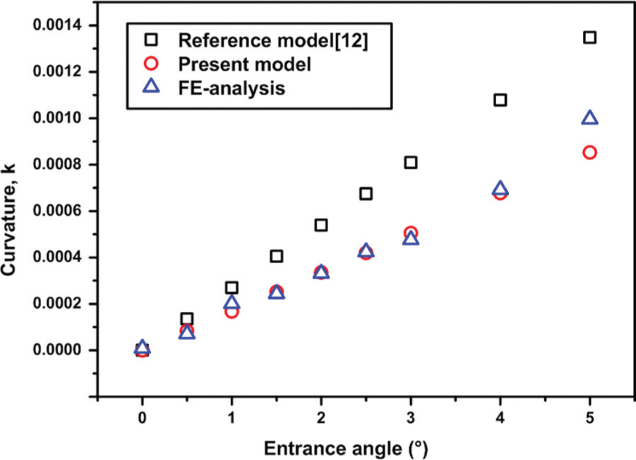
Comparison of strip curvatures predicted by reference model, proposed model and FE analysis.
Control model for revising FECs
Control model based on geometric relationship
The FECs generated by an arbitrary entrance angle are controlled by the adjustment mechanism of the WR angular speed ratio in the actual process. Some problems are faced in the control of the strip curvature values using the proposed theoretical model in the case of differential WR angular speed ratios.
Figure 11 shows the geometrical relations during asymmetrical strip rolling. The upper roll was operated at a higher speed than the lower roll. Assuming no slip between the WRs and the strip, the contact patch is calculated using equation (11)


Schematic illustration of deformed strip under different WR angular speeds.
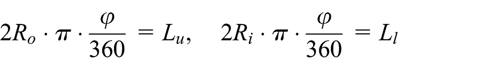
The ratio of the length of the lower surface of the strip to that of its upper surface is obtained as follows

where
FEA for verifying control model
The developed control model for the strip curvature was verified using 2D plane strain rolling simulations. The strip used was AISI 1045, and the general conditions are listed in Table 1. Tables 4 and 5 present the operating conditions for revising the FEC under various asymmetrical factors and its application. The proposed control model can successfully reduce the asymmetrical curvature.
Conditions for strip curvature control under different entrance angles and back tensions and its application.

WR: work roll.
Conditions for strip curvature control under different friction factors (entrance angle: 0°, back tension: 0 MPa) and its application.

WR: work roll.
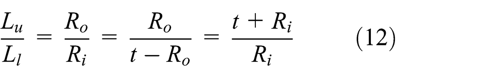
Figure 12 shows the shape of the deformed strips under applied curvature control at various entrance angles. As shown in Figure 12(a), the vertical deflection decreased from 12 and 30 mm to less than 5 mm for entrance angles of 1° and 3°, respectively. In another process, in which the entrance angle was 5°, the vertical deflection of the rolled strip decreased from 59 to 16 mm. As shown in Figure 12(b), the vertical deflection decreased from 9, 29 and 50 mm to 1, 11 and 21 mm for different friction factors. The control model with a back tension of 10 MPa resulted in excellent control of the strip curvature, as shown in Figure 12(c), and the vertical deflection was less than ±5 mm. Therefore, it is concluded that the proposed control model could reduce the FEC in a real hot strip finishing process.
Shape of deformed strip under applied curvature control: (a) different entrance angles without back tension, (b) different friction factors without back tension, and (c) different entrance angles with back tension of 10 MPa.
Conclusion
In this study, theoretical and control models for predicting and revising the FEC of a rolled strip in the hot finish rolling process were developed using the slab method and geometric relations, respectively. The analytical results were compared with the results of FEA. The main findings are summarised below:
A theoretical model based on the slab method was developed for predicting the FEC by considering asymmetrical factors such as the entrance angle of the strip, the friction factor and the back tension.
To validate the developed theoretical model, theoretical curvature values were compared with the results of FEA, and consequently, good agreement was found between the calculated results of the theoretical model and the measured results of FEA. The average error of the curvature was 0.00003.
A curvature control model based on geometrical and mathematical approaches that can reduce the strip curvature by the adjustment of the WR angular speed ratio was developed. FECs could be reduced considerably using the proposed control model. In particular, the control model with a back tension of 10 MPa resulted in a smaller vertical deflection of less than 5 mm in each case.
The theoretical and control models developed for predicting and revising, respectively, the FEC of a rolled strip can be used to improve the quality of the rolled product in the hot finish rolling process.
Footnotes
Academic Editor: ZW Zhong
Declaration of Conflicting Interests
The author(s) declared no potential conflicts of interest with respect to the research, authorship and/or publication of this article.
Funding
The author(s) disclosed receipt of the following financial support for the research, authorship and/or publication of this article: This work was supported by the National Research Foundation of Korea (NRF) Grant funded by the Korea government (MSIP) (No. 2012R1A5A1048294) and Hyundai Steel Company.