
Abstract
The drum driving system is one of the weakest parts of the long-wall shearer, and some methods are also needed to monitor and control the long-wall shearer to adapt to the important trend of unmanned operation in future mining systems. Therefore, it is essential to conduct an electromechanical dynamic analysis for the drum driving system of the long-wall shearer. First, a torsional dynamic model of planetary gears is proposed which is convenient to be connected to the electric motor model for electromechanical dynamic analysis. Next, an electromechanical dynamic model for the drum driving system is constructed including the electric motor, the gear transmission system, and the drum. Then, the electromechanical dynamic characteristics are simulated when the shock loads are acted on the drum driving system. Finally, some advices are proposed for improving the reliability, monitoring the operating state, and choosing the control signals of the long-wall shearer based on the simulation.
Introduction
Long-wall mining has been the dominant global coal mining method for decades. 1 The long-wall shearer as shown in Figure 1(a) is one of the main parts of the long-wall mining system. The drum driving system of the shearer is composed of the motor, the gear transmission system, and the drum (cutting head) as shown in Figure 1(b). The transmission chain of the drum driving system is so long with several parallel-axis gears and one stage or two stages of planetary gears. Moreover, the coal seam is usually inhomogenous with hard inclusion and rock intercalation, which induces the following features including heavy load, strong impact, and large fluctuation to the shear drum load. Thus, the drum driving system is one of the weakest parts of the drum shearer. The unmanned operation is an important trend in future mining systems, so some methods need to be found to monitor the operating state of the long-wall shearer and provide the control signals. The electric motor is like sensor which can be used to monitor the electromechanical systems.2–4 Therefore, it is essential to conduct an electromechanical dynamic analysis for the drum driving system of the long-wall shearer, which can provide some guidance for improving the dynamic performance and reliability, monitoring the operating state, and choosing the control signals of the long-wall shearer.

(a) Appearance and (b) drum driving system of the long-wall shearer.
Two kinds of electric motor models are usually used in electromechanical dynamic analysis including the steady-state and dynamic electric motor models. The steady-state model, namely, the mechanical characteristic of the electric motor, is usually obtained by steady-state electric circuit analysis 5 or by measurement, 6 while the dynamic electric motor model is obtained by dynamic electric circuit analysis, whose mathematical model is composed of a series of differential equations. 7 In this article, both the models are used in the electromechanical dynamic analysis and contrasted about the effects on the dynamic characteristics of the drum driving system.
The power source of the drum driving system is the asynchronous electric motor without control. For this kind of electromechanical system, when the load increases, the rotating speed of the electric motor will decrease, vice versa. The rotating speed of the motor is variable if the drum load fluctuates, that is, the gear transmission system operates under variable speed process. The planetary gear set is one of the key parts of the gear transmission because it is at the low-speed stage under heavy load and experiences more probability of damage. Therefore, to conduct the electromechanical dynamic analysis for the drum driving system, except the electric motor model, a dynamic model of planetary gear set is also needed that can be used in variable speed process. Moreover, the generalized coordinates in the dynamic model of planetary gear set should be angular displacements for convenience to be connected to electric motor model, because the generalized coordinate of the rotor is the angular displacement in the electric motor model usually.
Many dynamic models of planetary gears are proposed in the literature. A Kahraman 8 proposed a simplified purely torsional model of a single-stage planetary gear set to obtain torsional natural frequencies and compared with the natural modes obtained from a more sophisticated transverse–torsional model. J Lin and RG Parker 9 proposed an analytical model of planetary gears which include key factors affecting the vibration such as the gyroscopic effects and time-varying stiffness. Y Guo and RG Parker 10 proposed a dynamic model of planetary gear set involving tooth wedging and bearing clearance nonlinearity. W Kim et al. 11 proposed a dynamic model of planetary gear set in which the pressure angles and contact ratios are time-varying. These models8–11 are proposed to mainly investigate the vibration properties of gear transmission systems, and the vibratory translational and angular displacements8–10 are usually chosen as general coordinates. Therefore, these models8–11 can just be used in vibration analysis of transmission systems at a stable mean operating angular velocity with small fluctuation, not in variable speed processes. At present, some dynamic models12–14 of planetary gear set in non-stationary operations have been proposed based on these models9,15,16 by modifying the meshing stiffness according to the mean angular velocity. However, the generalized coordinates of these dynamic models12–14 are vibratory displacements, so it is not convenient to connect these models to the electric motor model for electromechanical dynamic analysis of the drum driving system. The variation in the mean rotating speed of gear transmission must be known in advance before using these dynamic models12–14 of planetary gears for non-stationary operations; however, most of the time, the rotating speed is usually unknown before the dynamic model is simulated especially when the dynamic electric motor model is utilized. A translational–torsional dynamic model of variable speed process has been proposed in Liu et al. 17 for the herringbone planetary gear set, in which the translational and angular displacements are chosen as the generalized coordinates. Based on Liu et al., 17 a torsional dynamic model of variable speed process for the spur planetary gear set is proposed with the angular displacements chosen as the generalized coordinates. This model is convenient to be connected to the electric motor model for the electromechanical dynamic analysis.
Some investigations have been conducted for the electromechanical dynamic analysis of the motor-gear system in previous literature. W Bartelmus 18 conducted the electromechanical dynamic simulations of one-stage and two-stage gearboxes for gearbox diagnostics. S Theodossiades and S Natsiavas 19 investigated the periodic and chaotic dynamic characteristics of motor-driven gear pair systems with backlash; in their model, it is not necessary to assuming a priori value for the constant mean angular velocity of the gear shafts. MT Khabou et al. 20 considered the steady-state model of the electric motor in the study of the dynamic characteristics of a spur gear pair in transient regime. F Chaari et al. 12 conducted a dynamic analysis of planetary gear transmission in non-stationary because of load fluctuation inducing rotating speed variation in the electric motor. A Meżyk 21 has conducted the electromechanical dynamic analysis for drum driving system on the long-wall shearer to minimize the maximal value of dynamic forces; however, the meshing stiffness is considered to be stable. G Clerc and colleagues4,22 proposed an electromechanical dynamic model for the gear-motor system to detecting faulty gears by monitoring the stator current. A Huttinger et al. 23 investigated the motor-controlled method including switched, open-loop controlled, and closed-loop controlled on the gear system by a special test stand developed by the SEW company. The steady-state model of the electric motor is utilized in various studies,12,18–20 while in other studies4,21–23 the dynamic motor model is utilized. These studies4,18–23 mostly focus on the parallel-axis gear pairs except the literature of Chaari et al. 12 However, the dynamic model of the planetary gear set in Chaari et al. 12 is constructed based on these models9,15,16 by modifying the meshing stiffness according to the mean angular velocity. The variation in the mean rotating speed of gear transmission must be determined from the external load fluctuation in advance based on the mechanical characteristics of the electric motor, 12 while, most of the time, the rotating speed is usually unknown before the electromechanical dynamic model is simulated especially when the dynamic electric motor model is utilized.
In this study, first, a torsional dynamic model of variable speed process for the spur planetary gear set is proposed with the angular displacements chosen as the generalized coordinates, which is convenient to be connected to the electric motor model for electromechanical dynamic analysis. Next, an electromechanical dynamic model for the drum driving system is constructed including the electric motor, the gear transmission system, and the drum. To simplify the electromechanical dynamic model, the rotary inertias of parallel-axis gears are equivalent to the electric motor rotor. However, the planetary set cannot be simplified because it is in the low-speed stage under heavy load and experiences more probability of damage, so more attentions should be paid to the dynamic meshing forces of the planetary gear set. Then, the electromechanical dynamic characteristics are simulated when the shock loads are acted on the drum. Furthermore, the effects of the electric motor models (steady-state or dynamic model) and the fluctuant meshing stiffness on the dynamic characteristics of the drum driving system are investigated based on the electromechanical dynamic simulation. The current characteristics are also investigated to find a way to monitor the cutting condition of the long-wall shearer. Finally, some advices are proposed for improving the reliability, monitoring the operating state, and choosing the control signals of the long-wall shearer.
Model of the electric motor
Two kinds of models for electric motor are usually used in the electromechanical dynamic analysis including the steady-state and dynamic electric motor models. The two kinds of models will be illustrated in the following.
Steady-state model of the electric motor
The steady-state model, namely, mechanical characteristic of the electric motor, reflects the relationship between the torque and the rotating speed of the electric motor. The mechanical characteristic of the electric motor can be derived by steady-state electric circuit analysis of the electric motor 5 as shown in Figure 2. The mechanical characteristic of the electric motor is derived as equation (1). Figure 3 shows the curve of the mechanical characteristic of the asynchronous electric motor. AC is the stable operation interval of the motor. B is the rated power point


Equivalent circuit of the asynchronous electric motor.

Mechanical characteristic of the asynchronous electric motor.
The notations in equation (1) are depicted in detail in Appendix 1. The symbol ′ represents the transformation of the circuit parameters from the rotor to the stator.
Dynamic model of the electric motor
In order to minimize the number of equations, the differential equations for the dynamic model of the electric motor are usually obtained in d-q coordinate frame. 7 The equivalent circuit of the electric motor in d-q coordinate frame is shown in Figure 4. The differential equations for the electric motor are derived as equation (2)

where


Equivalent circuit of the electric motor in d-q coordinate frame.
The notations in equation (2) are depicted in detail in Appendix 1. The symbol of ′ represents the transformation of the circuit parameters from the rotor to the stator.
Dynamic model of variable speed process for the planetary gear set
Because the rotating speed of the electric motor is variable due to the load fluctuation, a dynamic model of variable speed process for the planetary gear set is needed to conduct the electromechanical dynamic analysis of the drum driving system. Moreover, the angular displacements should be chosen as the generalized coordinates in the dynamic model of planetary gears for the generalized coordinate is the angular displacement of the rotor in the electric motor model as shown in section “Model of the electric motor.” Thus, a torsional dynamic model of variable speed process is proposed for the spur planetary gear set in this study, which is simplified from the translational–torsional dynamic model of variable speed process for the herringbone planetary gear set in Liu et al. 17 In this study, the planetary gear set is first transformed into parallel-axis external and internal gear pairs in the moving coordinate system to obtain the meshing forces, and then the Newton’s law in non-inertial coordinate system is utilized to obtain the equations of motion. The generalized coordinates in this torsional model are angular displacement, so it is convenient to be connected to the electric motor model for electromechanical dynamic analysis.
Calculation of meshing forces of parallel-axis external and internal gears
The power transmitted by the gear systems is very high and the dynamic meshing force should be paid more attentions to, so just the rotating degree of freedom for each gear is considered in the dynamic model as shown in Figure 5. The coordinate system is chosen as follows: x-axis is in the direction of off-line-of-action and y-axis is parallel to the line of action. The force analysis of external and internal gears is illustrated in Figure 5(a) and (b), respectively. The symbol Fy denotes the meshing force in y-direction. Figure 5 shows how Fy acts on gear 1. The symbol θj denotes angular displacement of gear j (j = 1, 2), respectively. The symbol rbj denotes base radius of gear j (j = 1, 2), respectively. Gears 1 and 2 are the driving and driven gears, respectively.
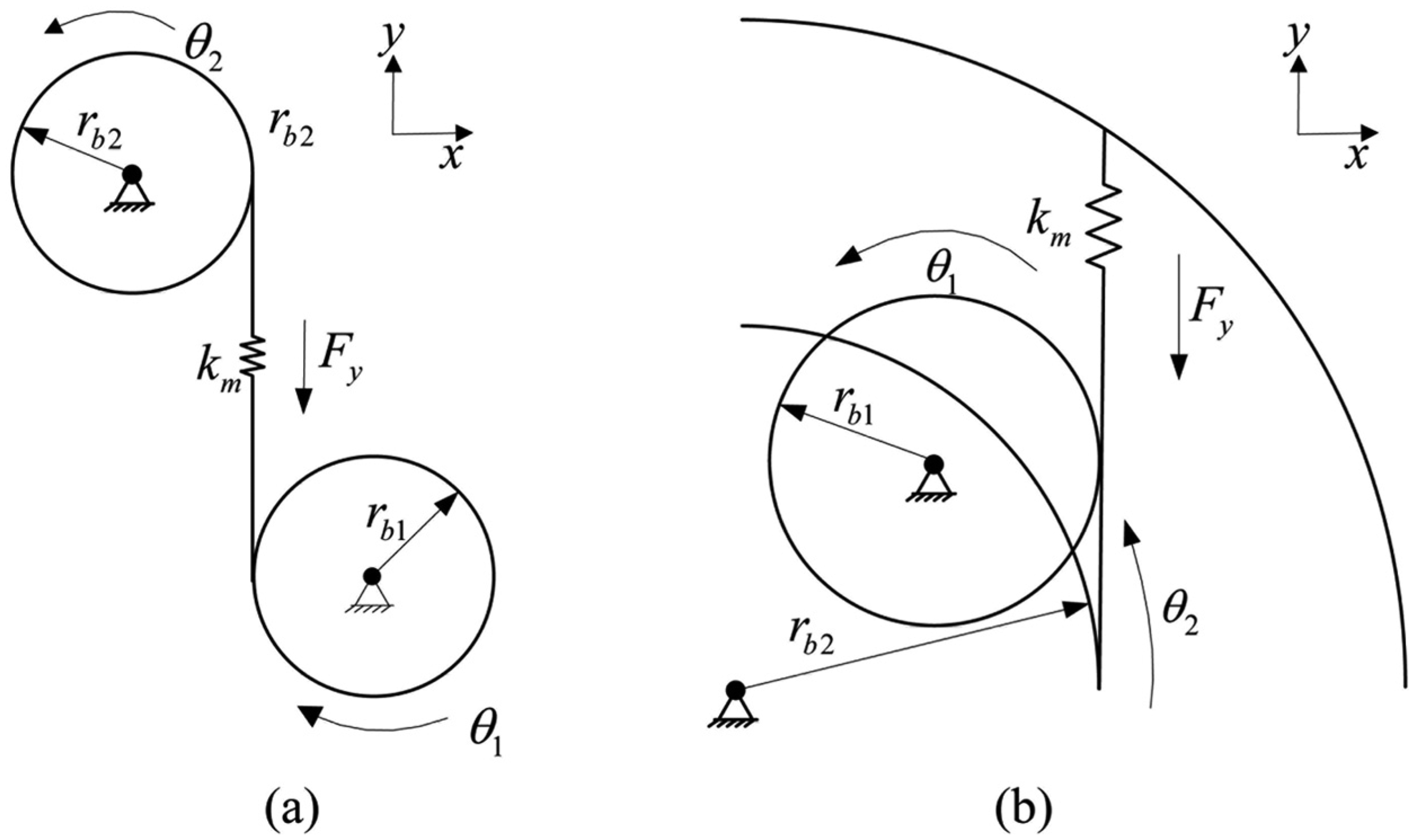
Illustration of force analysis of parallel-axis: (a) external and (b) internal gears.
The symbol δi denotes the y-direction deformation of ith (i = 1, 2,…, ceil (ε)) meshing tooth pair, respectively, where ε is the contact ratio, and the “ceil” function rounds ε to the nearest (higher) integer value. The symbol ei denotes the profile error excitation of the ith (i = 1, 2,…, ceil (ε)) meshing tooth pair. Because the proposed model here is for variable speed processes, the profile error excitations are assumed to vary with both the angular displacement of the driving gear (not time) and the position along the contact line.24–26
δi can be derived as equation (3)

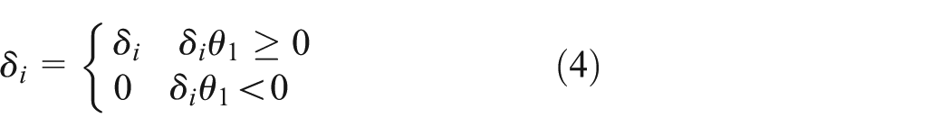
The meshing forces decrease to 0 when the teeth lose contact. 27 After transformation from planetary gears to parallel-axis gears in the moving coordinate, the sign of angular displacement of the driving gear (θ1) may be minus and the values for compressive deformations of the contact teeth are also minus; therefore, the deformation δi is modified as equation (4)
The meshing force of ith meshing tooth pair in the y-direction Fyi is derived as equation (5)

where
The meshing force between two gears in the y-direction Fy is given as

If we set δi = 1, the meshing stiffness can be obtained from equations (5) and (6). It is implied in equations (5) and (6) that the meshing stiffness is the periodic function of the angular displacement of the driving gear directly.
Dynamic model of the planetary gear set
In Figure 6, three kinds of coordinate systems are constructed: (1) the static coordinate system OXY; (2) the moving coordinate system oxy rotating with carrier; and (3) the moving coordinate system onξnηn (n = 1,…, N and N is the number of planets) rotating with the carrier, where ξn-axis is in the radial direction and ηn-axis is in the tangential direction. The angular displacements θi (i = s, r) are assigned to the sun and ring, respectively, which are measured in the moving coordinate system oxy. The symbol θc denotes the angular displacement of the carrier which is measured in the static system OXY. The symbol θpn denotes the angular displacement of the nth planet which is measured in the moving coordinate system oξnηn. [θsθrθcθp1…θpN] are chosen as the generalized coordinates to construct the dynamic model of planetary gear set. The symbol φn denotes the position angle of the theoretical center of nth planet, where φn = 2π(n − 1)/N. The symbols Ts and Tc denote the torque acting on the sun and carrier, respectively. The symbol Tr denotes the torque acting on the ring gear which is provided by the gearbox house, where Tr = −kθr (θr + θc). The symbol kθr denotes the torsional supporting stiffness of the ring which is provided by gearbox house because the ring is usually fixed on the gearbox house.

Dynamic model of the planetary gear set.
In the moving coordinate system, the planetary gear set can be transformed to parallel-axis external (sun–planet) and internal (planet–ring) gear pairs, as shown in Figure 7, and then, the meshing forces can be calculated as depicted in section “Calculation of meshing forces of parallel-axis external and internal gears.” For the transformed external gear pair, the sun is the driving gear, while for the transformed internal gear pair, the planet is the driving gear. The symbol θAjn (A = E, I; j = 1, 2; n = 1,…, N) denotes the angular displacement of gear j of the nth transformed external (E) and internal (I) gear pairs. The symbol FAyn (A = E, I; n = 1,…, N) denotes the meshing force of the nth transformed external (E) and internal (I) gear pairs in the y-direction. Figure 7 shows how these forces act on gear 1. The transformation relationships for the external and internal gear pairs are derived as equations (7) and (8), respectively

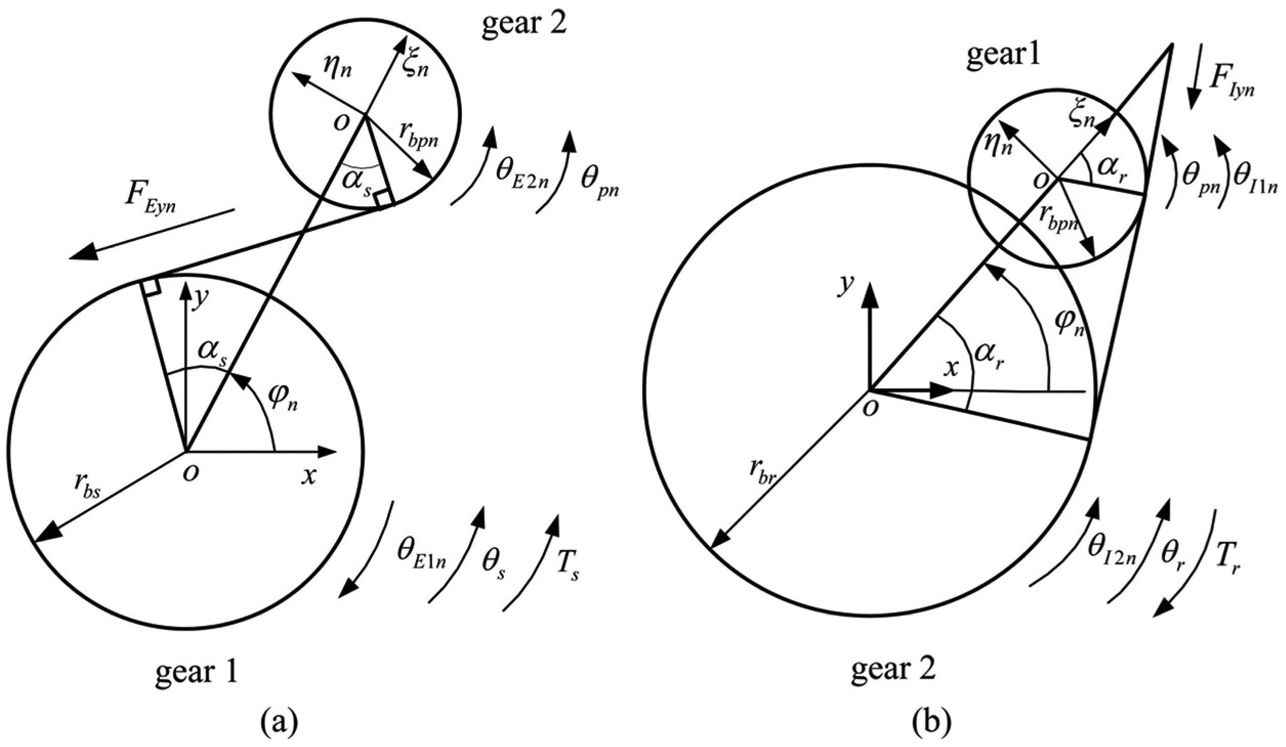
Transformation to parallel-axis gear pairs: (a) from the sun–planet gear pair to a parallel-axis external gear pair and (b) from the planet–ring gear pair to a parallel-axis internal gear pair.
Upon obtaining the meshing forces of the external and internal gear pairs, the Newton’s law in non-inertial coordinate system9,17 is utilized to obtain the equations of motion of planetary gears as shown in equation (9). The symbol rc denotes the planet distribution radius

Electromechanical dynamic model of the drum drive system
The drum driving system is composed of the motor, the gear transmission system, and the drum (cutting head) as shown in Figure 1(b). The gear transmission system is a long chain with a series of parallel-axis gears and a stage of planetary gear set. In this article, an electromechanical dynamic model of the drum driving system is constructed including the electric motor, the gear transmission system, and the drum as shown in Figure 8. To simplify the electromechanical dynamic model, the rotary inertias of the parallel-axis gear pairs and electric motor are equivalent to the axis of the electric motor rotor (Jmpe). The symbols kmpe and cmpe denote torsional stiffness and damping of the connection between the electric motor and the gear transmission, respectively. The symbol Jd denotes the rotary inertia of the drum; the symbols Mm and Md denote the torque acting on the electric motor rotor and drum, respectively; the symbols θm and θd denote the angular displacements of the electric motor rotor and drum, respectively; the symbols cpd and kpd denote the torsional damping and stiffness of the connection between the carrier and drum, respectively; imp is the transmission ratio of the parallel-axis gear pairs. The angular displacements of the sun θs in section “Dynamic model of variable speed process for the planetary gear set” are measured in the moving coordinate system, so the angular displacements of the sun in the static coordinate frame are θs+θc as shown in Figure 8.

Electromechanical dynamic model of the drum driving system.
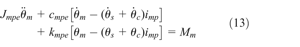
The torque acting on the sun (Ts) and carrier (Tc) is calculated as equations (10) and (11).The differential equation of the drum is derived as equation (12). The differential equation of the electric motor is derived as equation (13). Equations (10)–(13), the electric motor model in section “Model of the electric motor” and the dynamic model of planetary gears in section “Dynamic model of variable speed process for the planetary gear set” are combined for the electromechanical dynamic model of the drum drive system. If the steady-state motor model is used, Mm in equation (13) is calculated from equation (1) with ωm = dθm/dt. If the dynamic electric motor model is used in the electromechanical dynamic model, Mm in equation (13) is calculated from equation (2)


Electromechanical dynamic simulation and analysis
When the shearer cuts the normal coal seam and the fluctuation of the cutting force is small, the cutting force can be approximately simulated by constant force. When the shearer cuts hard inclusion or rock intercalation in coal seam, the cutting force can be approximately simulated by pulse force. The cutting force increases when the shearer cuts from soft coal seam to the hard coal seam, then the hauling speed will decrease leading to the decrease in the cutting force; therefore, the cutting force can also be simulated by the pulse force. The sudden-changing drum load easily happens when the long-wall shearer is operated unmanned, which is an obvious and dangerous feature of the drum load. The pulse load can reflect the feature of sudden-changing. As a result, the pulse force is used to study the effects of sudden-changing drum load on the long-wall shearer. Furthermore, the effects of the electric motor model (steady-state or dynamic model) and the fluctuant meshing stiffness on the dynamic characteristics are investigated based on the electromechanical dynamic simulation. The current characteristics are also investigated to find a way to monitor the cutting condition of the drum. The shock load is shown in Figure 9. It is a transient process at the beginning of the simulating time with initial rotating speed of the electric motor set as the synchronous speed, so the pulse load with width of 0.1 s is induced at 1 s after the steady-state process is reached. The parameters of the drum driving system are shown in Table 1.

Torque acting on the drum.
Parameters of the drum driving system.

The angular velocity of the electric motor during the simulating time is shown in Figure 10 when the steady-state and dynamic electric motor models are used. The initial rotating speed of the electric motor is set as the synchronous speed, so the rotating speed of the electric motor decreases at the beginning of the simulation and then reaches steady state at about 0.5 s. This initial transient process will be ignored in the analysis for the clarity of illustration. The angular velocity of the electric motor decreases when the shock load is acted and increases when the shock load is over as shown in Figure 10. This transient process caused by the shock load should be paid much attention in this study. The angular velocity of the electric motor during 0.9–1.4 s is shown in Figure 11. The steady rotating speed of the dynamic electric motor model is smaller than that of the steady-state electric motor model, and the fall of the rotating speed is also larger when the shock load is acted.

Angular velocity of the electric motor (ωm, 0–2 s).
Angular velocity of the electric motor (ωm, 0.9–1.4 s).
The angular velocity of the drum during 0.95–1.2 s is shown in Figure 12. The drum speed of the dynamic electric motor model is a little smaller than that of steady-state electric motor model under the stable external load (70,000 N m here), while the fluctuations of the drum speed are nearly the same. Under the shock load, the drum speed of the dynamic electric motor model decreases more than that of the steady-state model. Large fall of drum speed after the shock load needs to be avoided, because the drum load increases with the fall of the drum speed, which will make the drum speed decrease continually, and then, the drum load increases; this vicious circle may stop the drum drive system.
Angular velocity of the drum (ωd, 0.95–1.2 s).
In summary, compared with the steady-state electric motor model, the rotational speed of the drum driving system is lower for the dynamic electric motor model under stable drum load, and the fall of the rotational speed is larger when the shock load is acted on the drum. Hence, the dynamic electric motor model had better be chosen in the design stage for better speed stability of the long-wall shearer.
The electromagnetic torque of the electric motor during 0.9–1.4 s is shown in Figure 13. The fluctuation of the electromagnetic torque of the electric motor for the steady-state electric motor model is larger than that for the dynamic electric motor model under the stable external load. When the shock load is acted, the electromagnetic torque increases. The electromagnetic torque of the steady-state electric motor model increases more quickly than that of the dynamic model. When the shock load is removed at 1.1 s, the electromagnetic torque of the steady-state electric motor model decreases immediately; however, the electromagnetic torque of the dynamic model continues increasing and then decreases at about 1.114 s. The shock load–induced peak value of the electromagnetic torque for the dynamic electric motor model is larger than that for the steady-state model.
Electromagnetic torque of the electric motor (Mm, 0.9–1.4 s).
The dynamic meshing forces of the sun–planet gear pair of the planetary gear set under the stable and shock load are shown in Figure 14. When the shock load is acted, the dynamic meshing force increases immediately and reaches the steady state quickly. The dynamic meshing force reaches the steady state more quickly than the electromagnetic torque. The electromagnetic torque does not reach the steady state until the shock load is removed. The meshing forces of the sun–planet gear pair for the steady-state and dynamic electric motor model are nearly the same in amplitude and wave shape under both the stable and shock loads. That is, the electric motor model (steady-state or dynamic model) has little effect on the dynamic meshing forces of the sun–planet gear pair. The dynamic meshing forces of the planet–ring gear pair of the planetary gear set under the stable and shock load are shown in Figure 14(c) and (d). The amplitude of the meshing forces of the planet–ring gear pair for the dynamic electric motor model is larger than that for the steady-state model.
Dynamic meshing forces of the sun–planet gear pair (Fme) and planet–ring gear pair (Fmi) of the planetary gear set under the stable load (a, c) and shock load (b, d) when the fluctuation of the meshing stiffness is considered.
Figure 15 illustrates the dynamic meshing forces of the sun–planet and planet–ring gear pair of the planetary gear set when the fluctuation of the meshing stiffness is ignored. The fluctuation of dynamic meshing forces nearly disappears if the fluctuation of the meshing stiffness is ignored; moreover, there is nearly no distinction between the steady-state and dynamic electric motor model. Thus, it is an efficient way to reduce dynamic forces by eliminating the fluctuation of the meshing stiffness. Although the distinction between the steady-state and dynamic electric motor model is minimal if the fluctuation of the meshing stiffness is ignored in simulation, comparing Figures 14 and 15, it is necessary to consider the interaction of the meshing stiffness fluctuation and the dynamic electric motor model in the simulation for more reliable design of the long-wall shearer.
Dynamic meshing forces of the sun–planet (a; Fme) and planet–ring gear pair (b; Fmi) of the planetary gear set when the fluctuation of the meshing stiffness is ignored.
In a word, the amplitudes of the electromagnetic torque and dynamic meshing forces are larger if the dynamic electric motor model is used in the electromechanical dynamic analysis of the drum driving system. Therefore, the dynamic electric motor model is better chosen to obtain the force characteristic of the drum driving system for more reliable design of the long-wall shearer.
Another application of the dynamic electric motor model is to obtain the electrical characteristics of the drum driving system under shock load by electromechanical dynamic simulation. The a-phase current of the electric motor stator is shown in Figure 16. After the shock load is acted, the amplitude of the a-phase stator current increases but not obviously, so it is not convenient to monitor the operation condition of the drum driving system by a-phase stator current. If the stator currents are transformed to synchronous d-q frame, the electric supply frequency will be eliminated from the current signatures of the stator as shown in Figure 17. The d-axis current of the stator increases obviously after the shock load is acted. Comparing Figures 14 and 17, it is observed that the dynamic meshing force reaches the steady state more quickly than the d-axis stator current when the shock load is acted. The dynamic meshing force reaches the steady state quickly after the shock load, while the d-axis stator current does not reach the steady state until the shock load is over. That is, the variation in the d-axis stator current lags behind the variations in the meshing forces and external loads. Thus, if the d-axis stator current is used to monitor the long-wall shearer to adjust the cutting parameters (such as hauling speed) to adapt to the variable coal seam, the adjustment should made in advance, not the time when the current reaches the peak.

a-Phase stator current of the electric motor (isa).

d-Axis stator current of the electric motor in synchronous d-q frame (isd).
The d-axis stator currents are nearly coincided whether the fluctuation of the meshing stiffness is considered or not as shown in Figure 17. In reality, the d-axis stator currents are not identical but a little different as shown in Figure 18. The load perturbation on the rotor caused by the fluctuation of the meshing stiffness is of high frequency as shown in Figure 19. The motor with large inductance is like a low-pass filter, so the high-frequency perturbation rarely affects the stator current, that is, the load perturbation caused by the fluctuation of the meshing stiffness rarely affects the accuracy of monitoring the drum load by the d-axis stator current in the synchronous d-q frame.
d-Axis stator current of the electric motor in synchronous d-q frame (isd, 0.8–0.85).
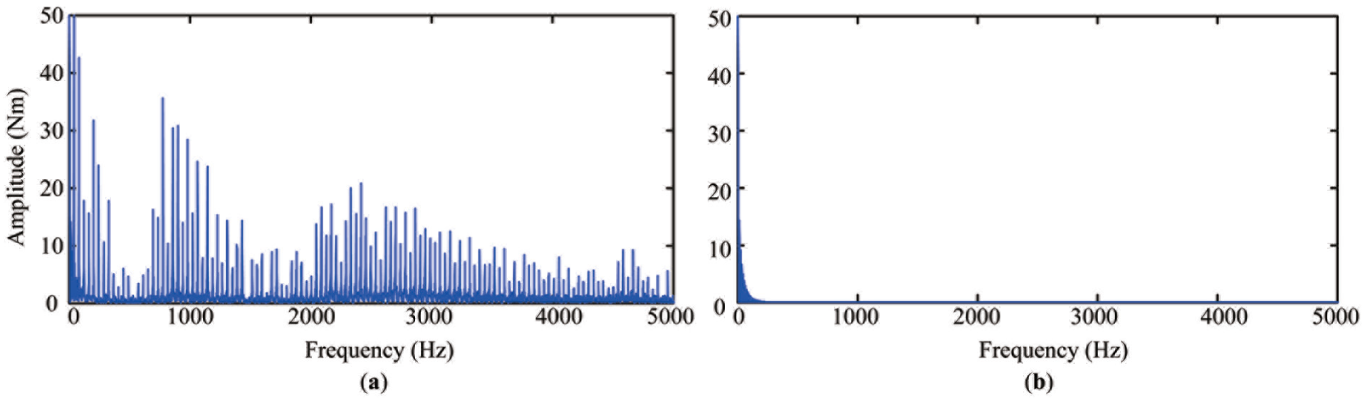
Frequency spectrum of the rotor load acted by the transmission system when the fluctuation of the meshing stiffness is (a) considered and (b) ignored.
In a word, the low-frequency drum load can be monitored by the stator current in the synchronous d-q frame, because the transformation from abc frame to synchronous d-q frame can eliminate the electric supply frequency from the current signatures. The high-frequency perturbation, such as the load perturbation caused by the meshing stiffness fluctuation, rarely affects the accuracy of this condition monitoring method, because the motor with large inductance is just like a low-pass filter. The variation in the d-axis stator current lags behind the variations in the force characteristics; thus, if the d-axis stator current is used to monitor and control the long-wall shearer, the effect of this delay should be considered.
Conclusion
In this study, a torsional dynamic model of variable speed process for the planetary gear set was proposed with the angular displacements chosen as the generalized coordinates, which was convenient to be connected to the electric motor model for electromechanical dynamic analysis. Then, the electromechanical dynamic model of the drum driving system was constructed including the electric motor, gear transmission system, and the drum. Finally, the electromechanical dynamic characteristics of the drum driving system were simulated when the shock loads were acted on the drum. The following conclusions were obtained from the numerical simulation:
Compared with the steady-state electric motor model, the rotational speed of the drum driving system is lower for the dynamic electric motor model under stable drum load, and the fall of the rotational speed is larger when the shock load is acted on the drum. The shock load inducing peak value of the electromagnetic torque for the dynamic electric model is larger than that for the steady-state model. The amplitudes of dynamic meshing forces are also larger if the dynamic electric motor model is used in the electromechanical analysis of the drum driving system. Thus, the dynamic electric motor model had better be applied for more reliable design scheme of the drum driving system.
The fluctuation of the meshing stiffness is the main cause of the dynamic meshing force impact. The impact of the dynamic meshing forces under stable drum load will disappear nearly, and the choice of the electric motor model (steady-state or dynamic) hardly affects the dynamic meshing forces if the fluctuation of the meshing stiffness is eliminated.
The electrical characteristics of the electric motor can be investigated when the dynamic electric motor model is applied in the electromechanical dynamic analysis of the drum driving system. This advantage is what the steady-state electric motor model lacks. The current characteristics can be used for monitoring the operating condition of the drum driving system.
The operation condition can be monitored by the stator current in the synchronous d-q frame. The high-frequency perturbation, such as the load perturbation caused by the meshing stiffness fluctuation, rarely affects the accuracy of this condition monitoring method. However, the variation in the d-axis stator current lags behind the meshing forces and external loads. This phenomenon should be considered if the d-axis stator current is used to monitor the cutting condition and control the long-wall shearer to adapt to the variable coal seam.
Therefore, to improve the reliability of the long-wall shearer, the following actions can be taken: the dynamic electric motor model is used in the design of long-wall shearer; some actions should be taken to reduce the fluctuation of the meshing stiffness; the stator current in the synchronous d-q frame can be used to monitor the cutting condition and adjust the long-wall shearer timely if the coal seam changes.
Footnotes
Appendix 1
cmpe torsional damping of the connection between the electric motor and the gear transmission (N m s/rad)
cpd torsional damping of the connection between the carrier and drum (N m s/rad)
ei (i = 1, 2,…) profile error excitation of ith meshing tooth pair (m)
FAyn (A = E, I; n = 1,…, N) meshing force of the nth transformed external (E) and internal (I) gear pair in y-direction (N)
Fy meshing force in y-direction (N)
Fyi meshing force of the ith meshing tooth pair in y-direction (N)
imp transmission ratio of the parallel-axis gear pairs
Jd rotary inertia of the drum (kg m2)
Jmpe rotary inertia of the electric motor rotor (kg m2)
kmpe torsional stiffness of the connection between the electric motor and the gear transmission (N m/rad)
kpd torsional stiffness of the connection between the carrier and drum (N m/rad)
Lm magnetizing inductance (H)
m 1 phase number, m1 = 3 here
Md torque acting on the drum (N m)
Mm torque of the electric motor (N m)
p number of pole pairs
rbj (j = 1, 2) base radius of gear j (m)
rc planet distribution radius (m)
s slip ratio, s = (ωs − ωm)/ωs
Tc, Ts, Tr torque acting on the carrier, sun and ring (N m)
Uϕ phase voltage (V)
Xm magnetizing reactance (Ω)
δi (i = 1, 2,…) deformation of ith meshing tooth pair (m)
θAjn (A = E, I; j = 1, 2; n = 1,…, N) angular displacement of gear j of the nth transformed external (E) and internal (I) gear pair, respectively (rad)
θc angular displacement of the carrier which is measured in the static system OXY (rad)
θd angular displacements of the drum (rad)
θi (i = s, r) angular displacements of sun and ring, which are measured in the moving coordinate system oxy (rad)
θj (j = 1, 2) angular displacement of gear j (rad)
θm rotor mechanical angular displacement (rad)
θpn angular displacement of the nth planet which is measured in the moving coordinate system oξnηn (rad)
θrotor rotor electrical angular position (p θm)
ω reference frame angular velocity (rad/s)
ωm rotor mechanical angular velocity (rad/s)
ωrotor rotor electrical angular velocity (p ωm)
ωs synchronous angular velocity (rad/s)
Acknowledgements
The authors would like to acknowledge the support and contribution from the State Key Laboratory of Mechanical Transmission, Chongqing University, China.
Academic Editor: Anand Thite
Declaration of conflicting interests
The author(s) declared no potential conflicts of interest with respect to the research, authorship, and/or publication of this article.
Funding
This research was funded by the National Major Basic Research Program of China (Fundamental Research of Unmanned Mining Equipment Used for Dangerous and Deep Coal Seam, 973 Program, Grant No. 2014CB046304).