
Abstract
This article presents a novel approach for actively suppressing the vibration within a two-link flexible manipulator to adapt the variation in the model parameters, which is composed of an input shaper and multimode adaptive positive position feedback. Input shaper is applied to shape the command to avoid the flexible vibration in the manoeuvre motion, and the residual vibration can be suppressed by a piezo actuator with the adaptive positive position feedback approach. To demonstrate the approach, two sets of piezoelectric actuator/stain gauge sensor pairs are bonded to the surface of the two-link flexible manipulator; slewing of the flexible link induces vibrations in the link that persist long after the motors stop moving. Vibration suppression is achieved through a combined scheme of input shaper–based motor motion control and an adaptive positive position feedback–based piezo actuator controller. Experimental results show the effectiveness of the proposed approach and its suitability for implementation in an existing robot.
Introduction
Compared with rigid manipulator systems, flexible parts provide a series of advantages in terms of lower overall mass and safer operation due to reduced inertia, faster system response, lower energy consumption, relatively smaller actuators and so on. 1 Although these advantageous features make the use of this type of robot extremely appealing, its control is typically difficult; these difficulties arise from two different tasks: end-effector positioning and the suppression of tip oscillations. 2
Numerous controllers have been designed to cancel the vibrations caused by structural flexibility, 3 which are described in the following introduction. However, most control schemes do not behave well during payload changes and uncertain dynamics because these events typically cause strong variations in the dynamics of the robot actuator, and most of these systems are composed of a single-link flexible arm. A number of different strategies have been applied to overcome this drawback; an example is variable stiffness control, 4 which provides schemes that vary controller parameters depending on certain criteria based on the data collected from previous movements. Another major effort has been devoted to the development of robust control, such as disturbance observer–based robust control, 5 which achieves the required insensitivity to small uncertainties in parameters. Sliding mode–based controllers 6 provide a simple and practical design for a flexible manipulator that experiences large payload variations and large Coulomb and viscous friction in their motors. However, feedback control of an end-effector position with only joint actuators is a non-collocated control problem and thus difficult to stabilize with undesirable non-minimum phase behaviour.
To enhance the flexible link’s vibration damping property, additional sensors and actuators can be applied; in this area, research has been intensifying over the past two decades regarding active vibration control methods for structures using smart materials, such as piezo ceramic (PZT) actuators bonded to the flexible link, suppressing link vibrations through the control of PZT actuators, 7 resulting in more effective vibration damping control. Many control strategies such as velocity feedback, neural networks, genetic algorithms, adaptive control and fuzzy control have been reported by various researchers; among them, positive position feedback (PPF) is essentially a second-order filter, which has been shown to be an effective vibration control method for the flexible systems embedded with smart materials.8,9 However, to apply PPF, the natural frequencies of the system must be determined exactly; otherwise, if the systematic parameters are poorly known or have varied due to, such as, the presence of the unmodelled dynamics, the effect of the PPF will be worsen. 10 A few forms of adaptive PPF have been developed for flexible structures,11,12 which vary in the way they are implemented.
Another alternative control strategy that performs best when structural vibrations are low is input shaping, which has widely been used and investigated by researchers. This method is a form of feedforward control, in which a sequence of joint input commands are regenerated to perform some tasks, while minimizing the excitation of the flexible modes. The concept of this method lies in the fact that the motion of a manipulator itself is the primary source of system vibration and hence shapes the torque applied, which does not contain energy at system natural frequencies and does not excite structural vibrations. 13 However, if the frequencies of the system are undermined especially varied by a large margin, the development of an adaptive command shaping technique for both single- and multimode cases is needed, where an adaptive scheme to update the parameters of the input shaper is presented during the manoeuvre.14,15 However, the adaptive tuning scheme usually requires tedious analyses to implement, and the additional sensors and increased controller complexity become significant drawbacks in the application. To reduce system vibrations to a satisfactory level with parameter variations and uncertain dynamics, the application of an inner-loop nonlinear controller to cancel some nonlinearity and to reduce the configurations dependence of the structural frequencies enhances the performance of the input shaping scheme. The filtered input shaper within an adaptive closed-loop position control loop is performed by Luo et al.; 16 the scheme is shown to be effective when plant dynamics are weakly nonlinear and time-invariant. Then, passivity between the strain measured at the base of the arm and the joint velocity–based control is proposed by Vicente et al. 17 to alleviate the problem of stability and steady-state error; the control scheme achieves precise tip positioning by combining precise joint positioning with a link vibration damping; however, this method is not particularly efficient in tracking a tip angle trajectory.
In this work, we focus on simultaneous positioning and vibration suppression for a two-link flexible manipulator driven by linear motors and surface-bonded piezoelectric actuators. Compared with previous research, the major contribution of this work is the experimental investigation of active vibration control of a system with significant nonlinearities and parameter variations; the system investigated is a two-link flexible manipulator with piezoelectric actuators and strain sensors bonded to these links during high speed and acceleration motion. Furthermore, an effective vibration control strategy and adaptive PPF vibration control with an optimal input shaper (OIS) are proposed and validated with the vibration control experiments presented.
The remainder of this article is organized as follows. In section ‘Experimental set-up and dynamical modelling’, the experimental set-up and dynamics modelling of the two-link flexible manipulator are presented. Then, the proposed vibration controller is designed in section ‘Controller design’. The experimental results are interpreted in section ‘Experimental study’. Conclusions are then given in section ‘Conclusion’.
Experimental set-up and dynamical modelling
Experimental set-up
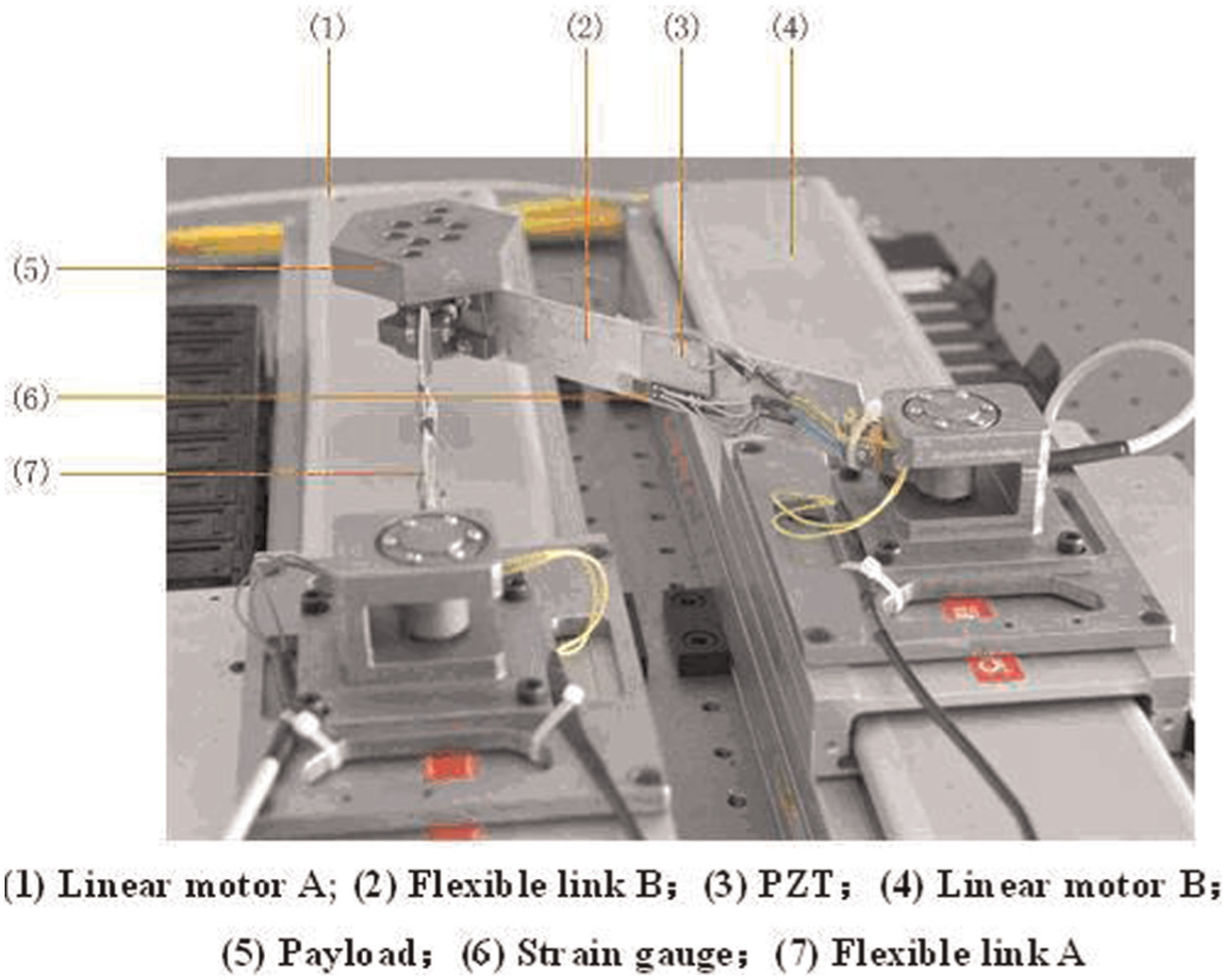
The experimental set-up illustrated in Figure 1 consists of the following components. 18 First, two Parker linear brushless direct current (DC) server motors (404LXRxx) are attached to the system base to drive a two-link flexible manipulator (Figure 2); every flexible link is instrumented with a pair of monolithic piezoelectric actuator plates and a pair of strain gauges assembled in a full-bridge configuration. With the adopted instrumentation, it is possible to achieve collocated control with curvature feedback, where the curvature is estimated based on the strain measured at the link surface by the strain gauge sensors. The motors are supplied with currents by a DC servo amplifier (Gemini series) operating in current mode. Second, a control voltage is generated from the digital-to-analogue converter DAC of a PC 31X DSP controller communicating with a Pentium PC through an ISA bus; the control processing is then performed by a DSP-based digital controller with a sampling period of 0.5 ms. Third, the load has a mass of approximately 0.25 kg and is mounted on the end point of the planar parallel mechanism driven by linear motors, whose linear motions are transformed to XY planar motion of end effector. Fourth, a motor position signal is fed back through an internal precision glass scale encoder, whose resolution is 0.5 µm; a PZT voltage amplifier is used to supply power for the PZT actuators, and a strain gauge amplifier provides signal conditioning for the full-bridge strain gauge set-up. The entire system is mounted on an air table for vibration isolation of the ground; the type of joints connecting the linear motors and the links is passive hinge. Fifth, the system repeatability is measured by an OFV3001-type fibre vibrometer made in Polytec Co. Ltd, whose resolution is 0.32 µm; the system settling time is measured by a capaNCDT 620–type non-contact capacitive displacement measurement made by Micro Epsilon Co. Ltd, whose resolution is 0.04 µm.

Experimental and test system set-up.
Schematic of the two-link planar flexible manipulator.
Dynamics modelling
The system has two rigid-body degrees of freedom (DOFs) in its linear motors XA and XB. Two linear motors actuate the mechanism, driving the rotation of the two flexible links. θ 1 and θ 2 are the generalized coordinates in the rigid-body rotation of the links. Euler–Bernoulli beam theory and the assumed mode method can be used to express the deflection at a point located at a distance of x 1 or x 2 from the linear motors for each flexible link in local coordinates (see Figure 3)


where


Diagram of the two-link flexible manipulator.
which can be formulated as vector coordinates in Cartesian frame XOY
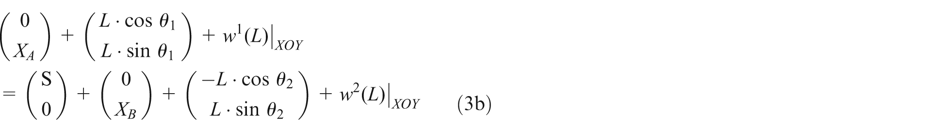
that is

where
In the first case, the first two modes are considered. Then, the linearized equations of motion of the mechanism can be deduced as
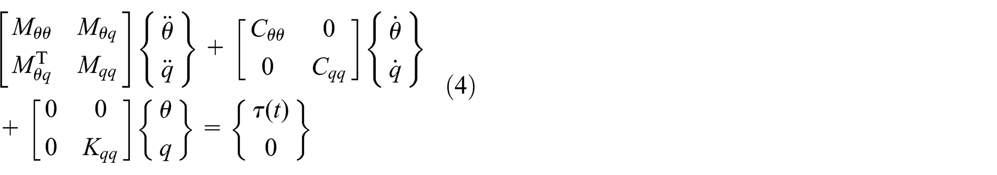
where Mθθ, Mθq
and Mqq
are the so-called rigid-motion term, rigid-flexible coupling terms and flexible deflection terms of mass, respectively; Cθθ
and Cqq
are the corresponding damping terms and
In a compact form, this can be written as

Equation (5) has two inputs; only torques are applied at the linear motors

where

Equation (5) can be rewritten in state-space form as

where

herein, by applying the voltages to the PZT patches, actuations can be produced in the slewing links, forming the multi-input multi-output system. The system can be modified to a multi-input system using F 1 and F 2 with
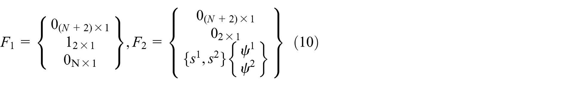

where


The resultant flexible mechanism system has four inputs (i.e. two at the linear motors and two at the PZT actuators) and four outputs (i.e. θ 1 and θ 2, which are the generalized coordinates in the rigid-body rotation of the links, and V in1 and V in2 at the strain gauges).
From equation (8), any one single input (i.e. PZT patch) to a single output (i.e. any strain gauge), the system can also be rewritten as

where

Modal shapes of the mechanism: first modal shape and second modal shape.
Resulting natural frequencies and damping ratios.

Controller design
This section describes the design of the input shaper with adaptive PPF for the flexible system explained in the previous section. As shown in Figure 5, vibration suppression is achieved through a combined scheme of input shaper–based motor motion control and an adaptive PPF-based PZT actuator controller. These approaches are described as follows: high performance is obtained by positioning the end point of the flexible mechanism from one point to another with minimum vibration.
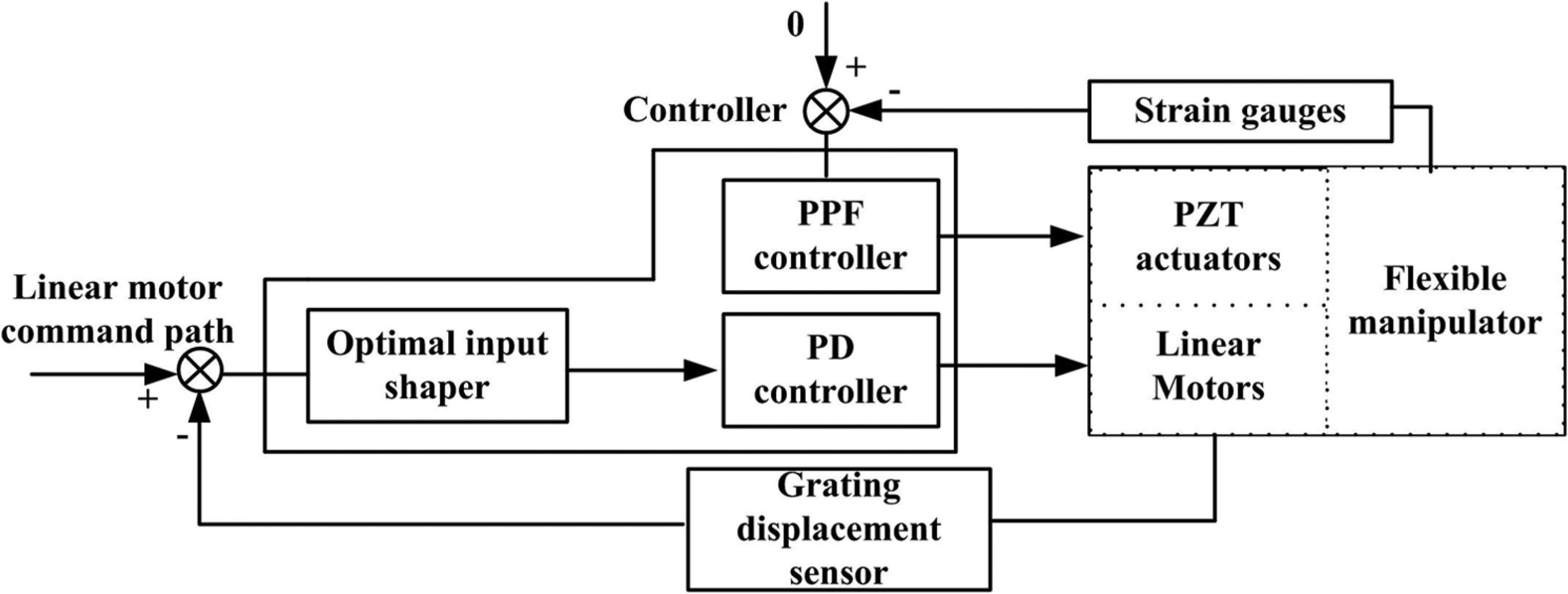
Controller scheme.
Optimal input shaping control at linear motors
For simplicity, an OIS
19
as a particular three-term command shaper will be used with the adaptive positive position feedback (APPF) approach for vibration control. For one single-mode equation (equations (15) and (16)), the solution of the equation can be described using a state-transfer matrix

To design an OIS, the following linear quadratic object is selected

where

Then, the necessary and sufficient condition of minimizing the object function can be given as


Combining equations (19)–(21), the solution can be obtained as

Substituting equation (17) into equation (22) and unifying parameters of the OIS, the amplitudes of three impulses are deduced as

where
APPF control at the PZT actuators
For the PZT actuator, the strain gauge output is usually used as the sensing signal multiplied by the amplifying gain Ga . Then, the PZT voltage is

Therefore, the applied electric field is as follows

where tb is the thickness of the PZT.
Then, using Hooks law in one dimension, the stress can be described as

where Eb denotes the Young’s modulus of the PZT and d 31 is the relevant electric displacement coefficient. Therefore, the expression for the bending moment caused by the PZT voltage can be described as

where tp is the thickness of the link; evidently, the force caused by the PZT by applying control voltage can be deduced after substituting in equation (24)

where l b is the length of the PZT. Thus

The control force equation then becomes

From equations (15), (16) and (30), the dynamics equation of the flexible system in modal frame is

where Zs
is the damping term,

When considering only the flexible modes of the system, a PPF controller can be designed in the next step for the PZT. For a system of the form shown in equation (32), PPF can be described by the compensator 9

where

where G is the gain term.
The above-mentioned four equations (equations (31)–(34)) can be formulated as following two relevant equations


Furthermore, the system equations can be transformed into state space for simple analysis

where

and the controller equations become

where

The PPF controller has the advantage of controlling low-frequency modes. However, PPF controller can roll off quickly at high frequencies; it is typically used to guarantee stability in the presence of uncontrolled in-bandwidth modes. The purpose of the controller is to reduce the effect of disturbances acting on the system and can be obtained by moving the poles of the closed-loop system towards the farthest point in the negative direction on the left-hand side of the imaginary plane; thus, necessary damping can be provided to the structure. However, due to nonlinearities and various uncertainties, system dynamics are not constant, and the PPF controller must be adjusted adaptively.
Adaptive parameter estimation
Using transfer function transformation, every output of the system can be written as 8

where


The output can also be expressed as

where u and y are the input and output of the plant, respectively. This is used to develop the adaptive law. Lumping all unknown parameters into the vector

and the following polynomial is used to filtering equation (40)

it can be obtained that

where


The estimation model can now be defined as

where

and

in which
A convex function of

where
Equation (47) is used to design an algorithm for reweighting the history data, and the recursive least-squares (RLS) approach with a forgetting factor is designed


where
Considering the full system, because of the fact that there are four outputs (i.e. the linear motor displacements and the strain gauge voltages) and four inputs (i.e. the linear motor torques and the PZT actuator voltages), the system can be described as a
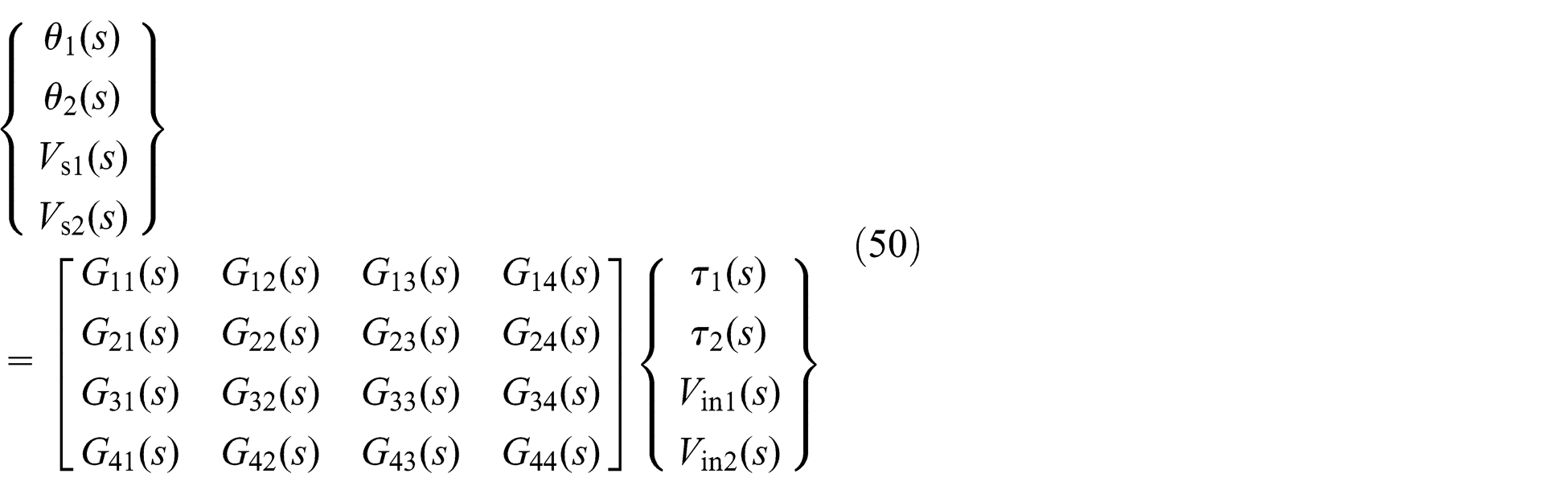
For the designed controller, the input shaper is used to shape the linear motor’s motion command with a proportional–derivative (PD) controller. Simultan-eously, for the PPF peer, an arbitrary initial value is given for the estimator and then adjusted in the transfer function (equation (50)). The estimation is updated to terminate when the error

Experimental study
The specifications of the experimental set-up and the corresponding parameters are given in Table 2. It is desired to slew the linear motor displacement 20 mm; the corresponding maximum velocity and acceleration are 0.5 and 19.6 m/s2, and the desired displacement and acceleration curve is shown in Figure 6. In this study, two situations are considered: (1) the same direction of motion in the two linear motors (X A = X B = 20 mm) and (2) the opposite direction motion in the two linear motors (X A = −X B = 20 mm). Four scenarios are considered: (1) PD-based motor motion controller only (PD), (2) PD-based motor motion control with adaptive PPF-based piezo actuator controller (PD + APPF), (3) PD control with input shaping–based motor motion controller (PD + IS) and (4) PD control with input shaping–based motor motion control and adaptive PPF-based piezo actuator controller (PD + IS + APPF).
Experimental system specifications.

N/A: newton/ampere; emf; electromotive force; PZT: piezo ceramic.

Desired displacement and acceleration of linear motors.
In this study, PD controller is first only used to control the linear motors in the same direction of motion; since no active vibration control is used, the flexible manipulator’s vibration is large, as shown in Figure 7; the result is measured using a laser Doppler vibrometer of Polytec, Inc. in the y-direction.

Residual vibration of end effector between PD and PD + APPF: (a) same direction of motion of the motors and (b) opposite direction of motion of the motors.
In the following study, besides the PD controller is applied to control the linear motors’ motion, the APPF controller is applied in the PZT to suppress the vibration, and the corresponding experimental results are shown in Figure 7. From the comparison with that of only PD controller, it can be seen that the flexible vibration has been reduced by a large margin. After APPF is used, the settling time (means that the vibration is reduced to 2 µm) has shortened from 430 ms (same direction of motion of the motors) and 640 ms (opposite direction of motion of the motors) to 115 and 240 ms, respectively. The corresponding strain gauge outputs and estimation of the natural frequency are shown in Figures 8 and 9, respectively, for comparison. It is shown that the vibration amplitude with the opposite direction of motion of the motors is much larger than the result with the same direction of motion of the motors; a similar situation in the severe various natural frequency with the reverse direction of motion of the motors is shown because of significant parameter changes caused by the variable configuration of the mechanism.
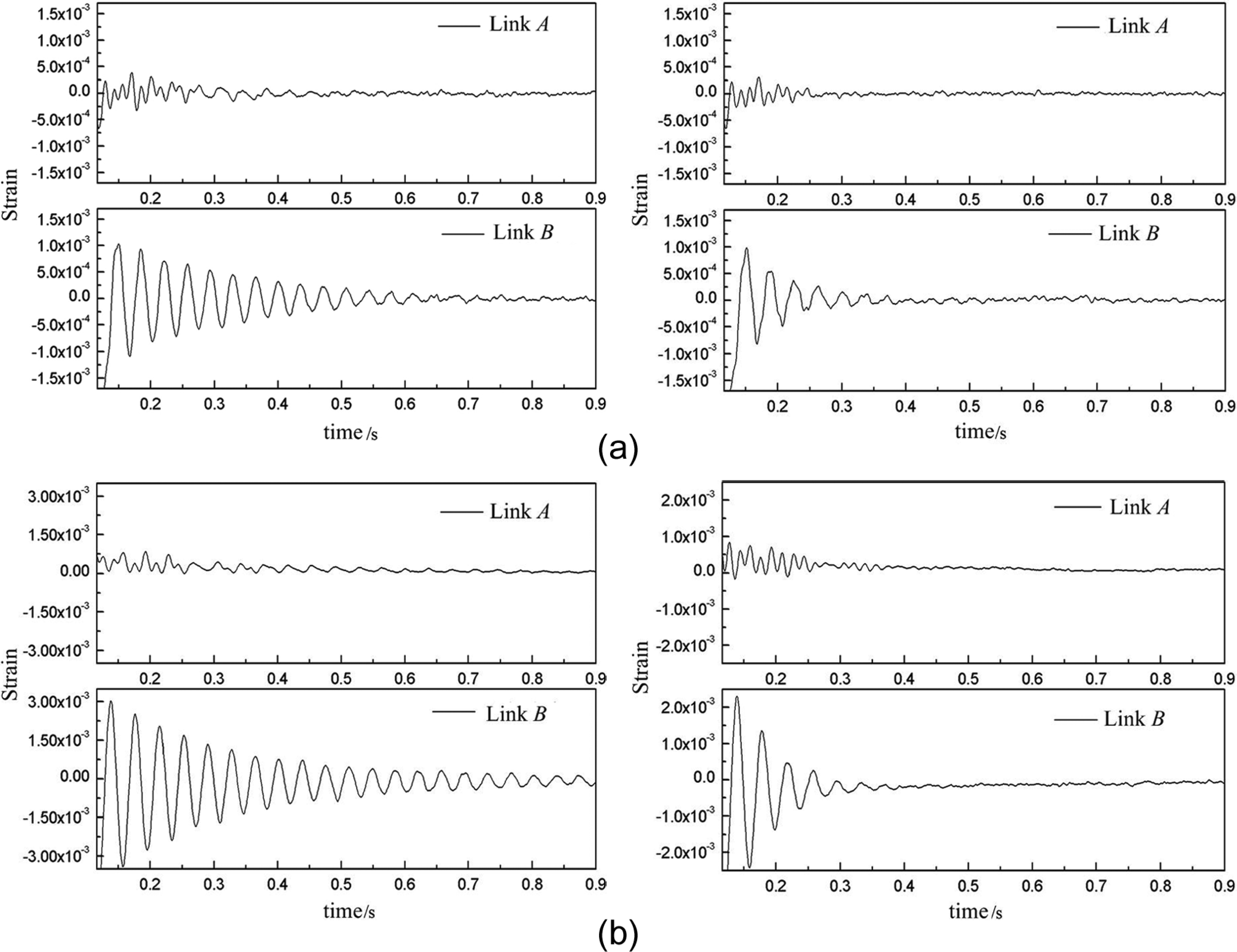
Strain gauge outputs of residual vibration between PD and PD + APPF: (a) same direction of motion of the motors and (b) opposite direction of motion of the motors.
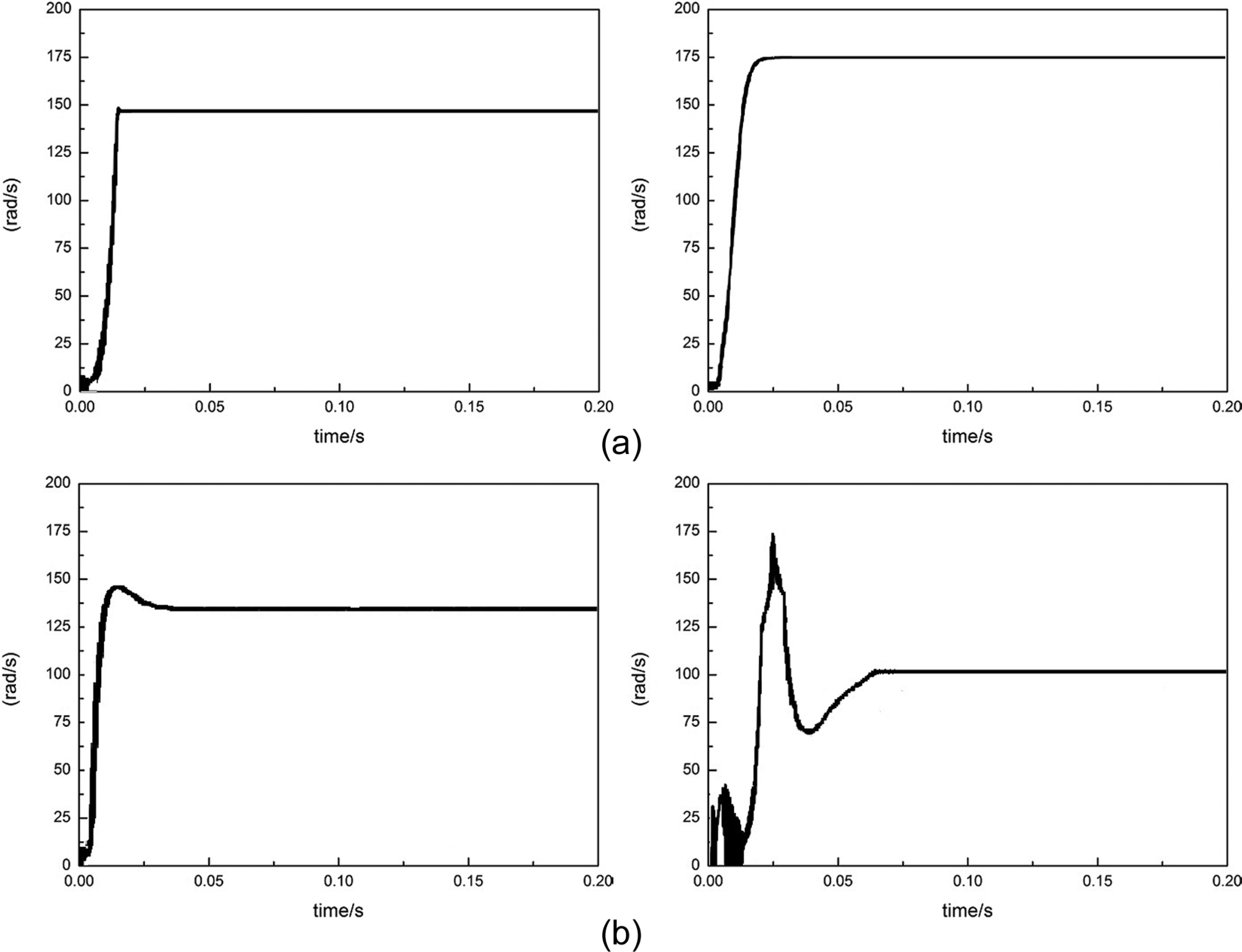
Estimation of natural frequencies: (a) same direction of motion of the motors and (b) opposite direction of motion of the motors.
In the end, vibration suppression is achieved through a combined scheme of input shaper–based motor motion control and an adaptive PPF-based piezo actuator controller; the experimental results are shown in the following figures compared with the traditional PPF approach. We can see that the vibration is reduced evidently by the combined scheme. Little residual vibration exists after 40 ms (same direction of motion of the motors) or 110 ms (opposite direction of motion of the motors). When two linear motors move in the same direction, the vibration frequency of the manipulators is nearly invariable; conversely, when moving in the opposite directions, nonlinear dynamics of the manipulator become violent and the vibration suppression of only the OIS significantly decreases. This test also shows the benefits of the APPF algorithm. Table 3 compares the different vibration control methods tested. From these experiments results, it can be clearly seen that since the proposed approach for active suppression vibration can adapt the variation in the model parameters exactly, therefore, compared with only input shaper or APPF approach, it can not only avoid the flexible vibration in the manoeuvre motion but also suppress the residual vibration effectively (Figure 10).
Comparison of the different vibration control methods tested.
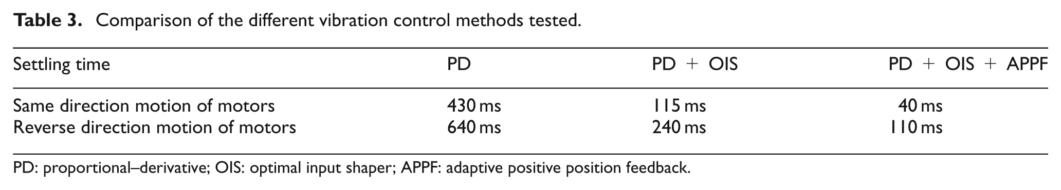
PD: proportional–derivative; OIS: optimal input shaper; APPF: adaptive positive position feedback.

Residual vibration of end effector between PD + OIS and PD + OIS + APPF: (a) same direction of motion of the motors and (b) opposite direction of motion of the motors.
Conclusion
In the article, a novel approach for actively suppressing the vibration within a two-link flexible manipulator is presented. OIS is applied to shape the linear motors’ command to avoid the flexible vibration in the manoeuvre motion, and the residual vibration is suppressed by a piezo actuator with the APPF approach due to parameter uncertainty. Since the proposed approach for active suppression vibration can adapt the variation in the model parameters exactly, therefore it can not only avoid the flexible vibration in the manoeuvre motion but also suppress the residual vibration effectively. The experiments are implemented on a two-link flexible manipulator to show the advantages of the proposed method compared with either of these control methods alone.
Footnotes
Appendix 1
Then, the Lagrange equations for the generalized coordinates are given by
herein, the kineto-elasto dynamics (KED) method is applied to carry out the differential calculation for the velocity and acceleration, which is a simplified model of a so-called pseudo-structure, including the coupled effect between the flexible deformation and the rigid-body motion. Then, the equations of motion of the mechanism can be deduced as
where
A 11 = 2.8635 + 2496.11CC 2 + 197.232KK × cos θ 1 + 13293.3KK 2
A 12 = −2496.11CC 2 − 98.616KK × cos θ 1−13293.3KK 2 + 22.673CC × cos θ 2
A 22 = 2.2876 + 2496.11CC 2 − 45.346CC × cos θ 2 + 13293.3KK 2
B 11 = 98.616AA × cos θ 1 + 2496.11CC × DD + 13293.3KK × AA−98.616KK 2 × sin θ 1
B 21 = −2496.11 × CC × DD + 22.673 × DD × cos θ 2−13293.3 × KK × AA − 22.673 × CC 2 × sin θ 2
A 21 = A 12; B 12 = −B 11; B 22 = −B 21
Academic Editor: Farzad Ebrahimi
Declaration of conflicting interests
The author(s) declared no potential conflicts of interest with respect to the research, authorship and/or publication of this article.
Funding
This work was jointly supported by the National Science Foundation of China (Grant Nos 51375034 and 61327809).