
Abstract
The mixed laminar boundary layer flow and heat transfer on a permeable stretched surface moving with prescribed skin friction are studied. Three major cases, which correspond to complete similarity solutions, are considered. The cases are combinations of power law indices n and m representing temperature and skin friction distributions, respectively. The first case (n = 0, m = 0.5) corresponds to isothermal stretched surface with skin friction at the surface scales as x 1/4. The second case (n = 1, m = 1) is a linear temperature and skin friction distribution along the vertical stretched surface. The third case (n = −1, m = 0) represents inverse temperature variation along the surface with prescribed skin friction of the order of x −1/2. Similarity solutions are obtained for the surface stretched in a stagnant air with Prandtl number = 0.72. The effect of suction/injection velocity (fw ) and the buoyancy parameter (λ) is studied in detail. The results show that the heat transfer coefficient along the surface is enhanced for assisting flow (λ > 0) at any value of fw for the first and second cases, while it is reduced for the third case. However, the opposite is true for the opposing flow (λ < 0). Furthermore, suction enhances the heat transfer coefficient, whereas injection degrades it at any fixed λ for the first and second prescribed skin friction boundary conditions, and the opposite is true for the third case.
Keywords
Introduction
Manufacturing processes involve many applications of continuously moving surfaces through an otherwise quiescent medium. Such processes are hot rolling, wire drawing, spinning of filaments, metal extrusion, crystal growing, continuous casting, glass fiber production, and paper production.1–3 After it was initiated by Sakiadis, 4 many researchers have published a lot of articles on the subject of stretched surface.5–14 Those researchers were interested in using different velocity boundary conditions at the surface in addition to the thermal ones. A new research has been initiated by Magyari and Keller, 15 where the stretched surface problem was solved by applying a prescribed skin friction instead of velocity at the boundary. Their results for impermeable surface have shown remarkable deviation of velocity, temperature, and heat flux profiles than those associated with prescribed velocity boundary conditions. Permeable stretched surface with uniform velocity and temperature was considered by Erickson et al. 16 and Fox et al.; 17 however, Gupta and Gupta 18 and Chen and Char 19 have reported it for linearly moving surface with different thermal boundary conditions. Furthermore, Ali 20 has reported a general case of using power law profiles of temperature and velocity as boundary conditions. Analytical and computational analyses of a surface moving with rapidly decreasing velocities have been reported by Magyari et al. 21 The permeable surface moving with decreasing velocity has been studied analytically by Magyari and Keller. 22 Uniformly moving vertical surface with temperature inversely proportional to the distance has been studied by Ingham. 23 Ali and Al-Yousef24,25 have studied laminar mixed convection of a vertical surface moving with uniform velocity and subject to various thermal boundary conditions, and the case of rapidly decreasing velocity was considered by Ali. 26 The initiated prescribed skin boundary condition 15 was extended for isothermal permeable plate using three different profiles of prescribed skin friction by Ali and Al-Salem. 27 Their results showed enhancements in Nusselt numbers for constant suction or injection parameter at the suction limit and deterioration at the injection limit. Preliminary results for buoyancy effect on a stretched surface with suction or injection with surface temperature varying inversely with the vertical distance x and with prescribed skin friction scaled as x −1/2 were reported by Ali. 28
This article extends the work of Ali and Al-Salem 27 and that of Ali 28 for mixed convection where the buoyancy parameter λ plays a very important role. The surface is assumed to be permeable moving with prescribed skin friction profiles of different orders of magnitude x instead of the regular way of defined stretching velocity at the surface. The analysis is focused on three different combinations of thermal and skin friction exponents n and m, respectively: (n = −1, m = 0), (n = 0, m = 0.5), and (n = 1, m = 1) which correspond to complete similarity solutions. This study is analyzed for Prandtl number (Pr) = 0.72. The advantage of using such new skin friction boundary conditions could be interpreted as simulation to any physical real situation which may arise during the process of stretching surfaces.
The mathematical formulation of the problem is presented in section “Mathematical analysis,” followed by the numerical solution procedure in section “Numerical solution procedure.” Results and discussion are reported in section “Results and discussion,” and finally, the conclusions are given in section “Conclusion.”
Mathematical analysis
Consider the steady two-dimensional motions of convective boundary layer flow induced by a moving vertical surface with suction or injection at the boundary. For incompressible viscous fluid environment with constant properties, the equations governing this convective flow can be written as


subjected to the following prescribed skin friction coefficient boundary conditions

The x coordinate is measured along the moving surface from the point where the surface originates, and the y coordinate is measured normal to it (Figure 1). Positive or negative ν implies injection or suction at the surface, respectively. The x and y velocity components are u and ν, respectively. Similarity solutions, which were developed by Magyari and Keller, 15 arise when the following assumptions and their necessary derivatives are applied in equations (2) and (3). The detailed description and derivation of the similarity conditions, assumptions, and equations can be found in Magyari and Keller 15


Schematic diagram of induced boundary layers adjacent to a vertical moving surface with prescribed shear stress boundary conditions.
and the shear stress and the heat flux at the surface are given by


It should be mentioned that positive m indicates that the surface is accelerated from the extruding slit, while negative m indicates that the surface is decelerated, where


To satisfy the similarity solution, equation (10) must be x independent, and therefore, n must be equal to 2m − 1. Using this necessary condition, equation (10) can be written as

where


In deriving the second boundary condition in equation (13), the horizontal injection or suction speed vw must be a function of the distance from the leading edge (for m≠ 1). Consequently, vw is given by

The quantity f(0) = fw will be referred as the dimensionless suction/injection velocity. In this way, fw = 0 corresponds to an impermeable surface, fw > 0 to suction (i.e. vw (x) < 0), and fw < 0 to lateral injection (i.e. vw (x) > 0) of the fluid through a permeable surface. The temperature of the injected fluid is assumed to coincide with the local temperature Tw (x) of the stretching surface.
The local skin friction coefficient, local Reynolds number, and the Nusselt number are given at the surface by


Numerical solution procedure
The fourth-order Runge–Kutta method was used to solve the transformed differential equations (11) and (12) subject to boundary conditions (13) and (14). Solutions are developed for different values of λ and fw
. At specified fw
and λ, the values of
Results and discussion
Equations (11) and (12) are solved numerically for three different combinations of n and m according to the necessary relation mentioned earlier to ensure complete similarity. Solutions are obtained for Pr = 0.72 (air) and for suction/injection parameter fw = 1, 0.5 corresponding to suction, 0 for impermeable, and −0.5 and −1.0 for injection at the surface and for different buoyancy parameters λ.
Velocity and temperature profiles
Samples of the velocity profiles (solid lines) and temperature distributions (dashed lines) for n = 0 and m = 0.5, which correspond to skin friction at the surface that scales as x 1/4 (first case), are shown in Figure 2(a)–(c) for injection fw = −1, impermeable fw = 0, and suction fw = 1, respectively. As it can be seen from these figures, injection, in general, increases the velocity boundary layer thickness at any fixed λ, and the opposite is true for suction. In addition, injection increases the thermal boundary layer thickness, and the opposite is true for suction as compared to the impermeable case. Those figures also show that as λ increases, the velocity at the surface increases which enhances the thermal characteristic by reducing the thermal boundary layer as seen for any fw . It should be noted that similar curves are obtained for the second case where m = 1 and n = 1 which represents linear skin friction distribution at the surface. The temperature profiles of the third case which characterizes by n = −1 and m = 0 for inverse temperature variation along the surface with prescribed skin friction of the order of x −1/2 are shown in Figure 3(a)–(c) for injection fw = −0.5, impermeable fw = 0.0, and suction fw = 0.5, respectively. The temperature profiles of these figures are different than those shown for cases 1 and 2 in a sense that they overshoot near the surface where the heat transferred from the medium to the surface tends to reduce the Nusselt numbers as will be seen in the subsequent figures. As seen in these figures for the same λ, injection increases the slope at the surface and suction reduces it. However, for all values of fw , increasing λ reduces the thermal boundary layer thickness and also increases the gradient of heat transfer at the surface.
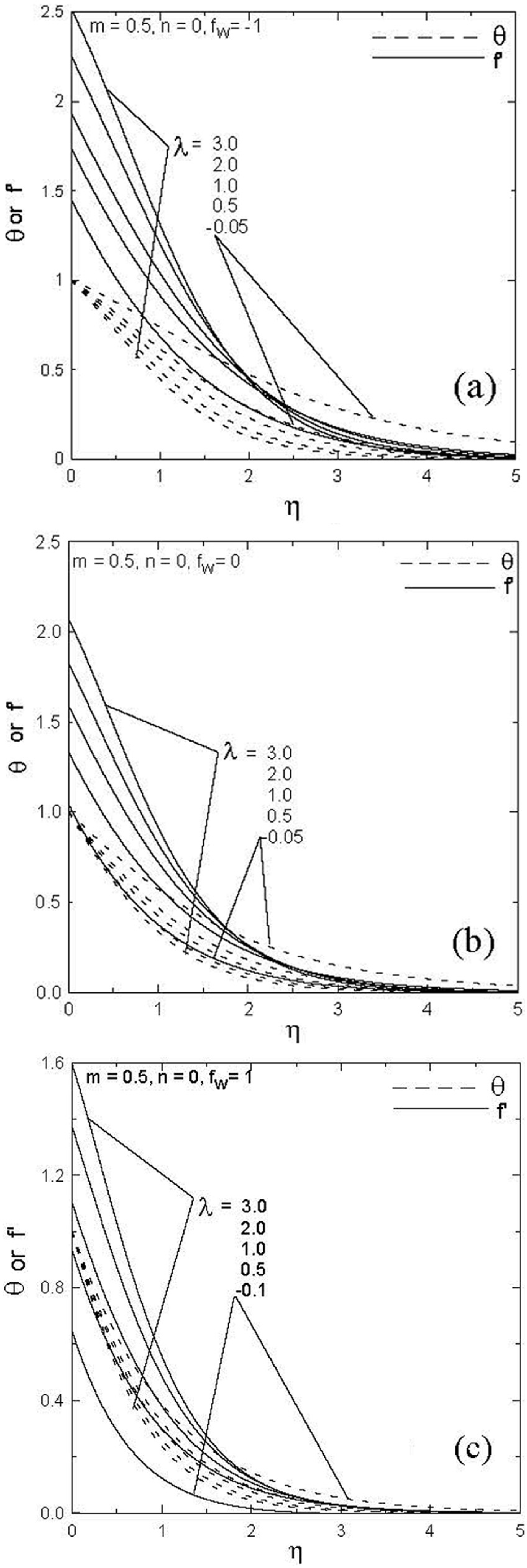
Samples of velocity and temperature profiles at different buoyancy parameters λ for case 1 (m = 0.5 and n = 0): (a) fw = −1 (injection), (b) fw = 0 (impermeable surface), and (c) fw = 1 (suction).

Samples of temperature profiles at different buoyancy parameters λ for case 3 (m = 0 and n = −1): (a) fw = −0.5 (injection), (b) fw = 0 (impermeable surface), and (c) fw = 0.5 (suction).
Overall velocity and heat transfer results
The effect of λ on the dimensionless velocity at the surface for skin friction scales as x
1/4 for different values of fw
is shown in Figure 4. In this comprehensive figure, it is clear that the velocity increases as λ increases for any fixed fw
and also increases as fw
moves from suction (fw
= 1) to injection (fw
= −1) at any fixed λ. The right side of the vertical dashed line shows the predominant natural convection effect on the velocity at the surface, which is assigned as assisting flow; however, opposing flow is assigned on the left side of the vertical dashed line where the velocity decreases for negative λ. To illustrate the region of predominant natural convection effect on the velocity, ±5% increase/decrease in the value of
Velocity profiles at the surface for different suction or injection parameters fw for case 1 (m = 0.5, n = 0). The vertical dashed line separates the assisting and opposing flow limits. Circle and square symbols show the critical points for predominant natural convection for assisting or opposing flow, respectively.
Critical values of predominant natural convection at different suction or injection fw of the first case (n = 0, m = 0.5) corresponding to isothermal stretched surface with skin friction at the surface scales as x 1/4.

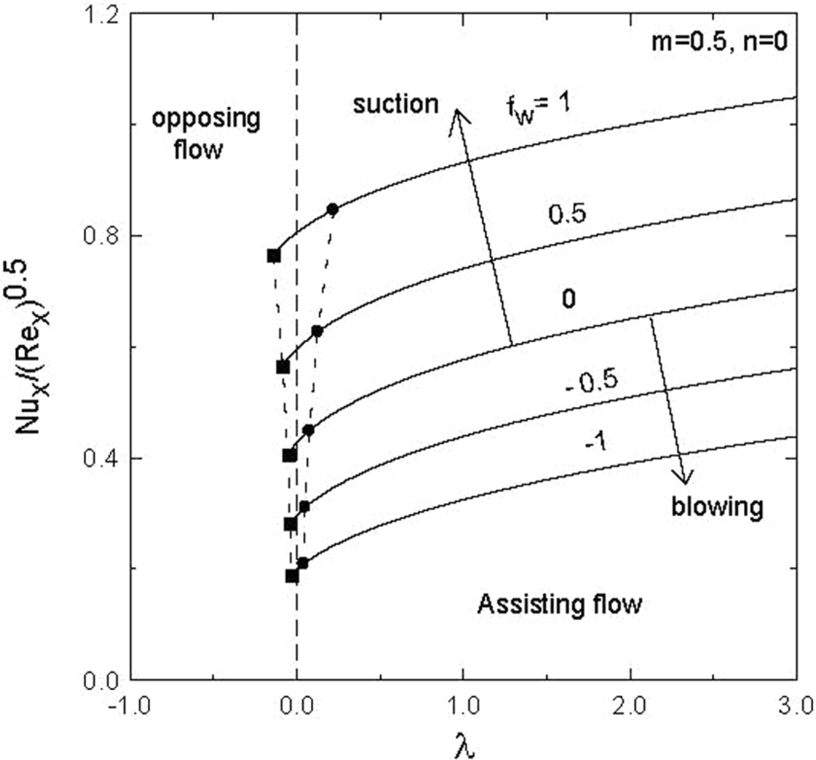
Dimensionless heat transfer coefficient profiles at the surface for different suction or injection parameters fw for case 1 (m = 0.5, n = 0). The vertical dashed line separates the assisting and opposing flow limits. Circle and square symbols show the critical points for predominant natural convection for assisting or opposing flow, respectively.

Entrainment velocity profiles for different suction or injection parameters fw for case 1 (m = 0.5, n = 0). The vertical dashed line separates the assisting and opposing flow limits. Circle and square symbols show the critical points for predominant natural convection for assisting or opposing flow, respectively.

Velocity profiles at the surface for different suction or injection parameters fw for case 2 (m = 1.0, n = 1.0). The vertical dashed line separates the assisting and opposing flow limits. Circle and square symbols show the critical points for predominant natural convection for assisting or opposing flow, respectively.

Dimensionless heat transfer coefficient profiles at the surface for different suction or injection parameters fw for case 2 (m = 1.0, n = 1.0). The vertical dashed line separates the assisting and opposing flow limits. Circle and square symbols show the critical points for predominant natural convection for assisting or opposing flow, respectively.

Entrainment velocity profiles for different suction or injection parameters fw for case 2 (m = 1.0, n = 1.0). The vertical dashed line separates the assisting and opposing flow limits. Circle and square symbols show the critical points for predominant natural convection for assisting or opposing flow, respectively.
Critical values of predominant natural convection at different suction or injection fw of the second case (n = 1.0, m = 1.0) of linear temperature and skin friction distributions along the vertical stretched surface.


Velocity profiles at the surface for different suction or injection parameters fw for case 3 (m = 0.0, n = −1.0). The vertical dashed line separates the assisting and opposing flow limits. Circle and square symbols show the critical points for predominant natural convection for assisting or opposing flow, respectively.

Dimensionless heat transfer coefficient profiles at the surface for different suction or injection parameters fw for case 3 (m = 0.0, n = −1.0). The vertical dashed line separates the assisting and opposing flow limits. Circle and square symbols show the critical points for predominant natural convection for assisting or opposing flow, respectively.

Entrainment velocity profiles for different suction or injection parameters fw for case 3 (m = 0.0, n = −1.0). The vertical dashed line separates the assisting and opposing flow limits. Coordinates of critical points for predominant natural convection for assisting or opposing flow are shown in Table 3.

Comparison between case 1 (m = 0.5, n = 0.0) and case 2 (m = 1.0, n = 1.0) of the dimensionless heat transfer coefficient profiles at the surface for all fw showing the enhancement of case 2 over case 1.

Comparison between the three cases (m = 0.5, n = 0.0), (m = 1.0, n = 1.0), and (m = 0.0, n = −1.0) of the velocity profiles for all fw showing more increase in the velocity at the surface due to case 3 followed by cases 1 and 2.

Comparison between case 1 (m = 0.5, n = 0.0) and case 2 (m = 1.0, n = 1.0) of the velocity profiles for all fw showing more increase in the entrainment velocity at the surface due to case 3 (not shown, beyond the scale) followed by cases 1 and 2.
Critical values of predominant natural convection at different suction or injection fw of the third case of n = −1 and m = 0 for inverse temperature variation along the surface with prescribed skin friction of the order of x −1/2.

Conclusion
Heat transfer and flow field characteristics of a stretched permeable surface subject to mixed convection with prescribed skin friction are investigated for three different skin friction and temperature boundary conditions corresponding to (m = 0.5, n = 0), (m = 1.0, n = 1.0), and (m = 0.0, n = −1). The results show that at the surface, the dimensionless stretching velocity and the entrainment velocity increase as the buoyancy parameter λ increases for any fw
for the three cases. The highest increase in these velocities are reached by the effect of the third case (m = 0.0, n = −1) followed by (m = 0.5, n = 0.0) and then by (m = 1.0, n = 1.0). It is also shown that increasing λ enhances the dimensionless heat transfer coefficient for the first and second prescribed skin friction boundary conditions; however, it degrades it for the third case. Furthermore, for constant buoyancy parameter λ, suction at the boundary increases the heat transfer, whereas injection degrades it for the first and second cases. As for the third case, the heat transfer decreases as λ increases for all fw
. Finally, critical values of λ,
Footnotes
Appendix 1
Academic Editor: Hua Meng
Declaration of conflicting interests
The author(s) declared no potential conflicts of interest with respect to the research, authorship, and/or publication of this article.
Funding
The author(s) disclosed receipt of the following financial support for the research, authorship, and/or publication of this article: This work was supported by the Deanship of Scientific Research at King Saud University through the research group project no. RGP-VPP-080.