
Abstract
Rain–wind–induced galloping phenomenon often occurs on overhead transmission tower-lines system, just as icing galloping and vortex-excited vibration; this kind of instability oscillation can cause power-line breakage or tower failure. However, the existing theoretical models of rain–wind–induced galloping are mainly based on the hypothesis of the overhead power-lines with fixed ends, which is inconsistent with the actual operation situation. Therefore, this article thus presents a preliminary theoretical study and proposes a new theoretical model taking into account the effect of tower excitations on the in-plane galloping of the overhead power-line and on the motion of the upper rain-line. The theoretical model is solved by Galerkin method and verified by the comparison with the test data obtained in the available literature involved with the overhead power-lines with fixed towers or moving towers. It turns out that the tower excitations may intensify the in-plane galloping amplitude of the overhead power-line within a certain range of frequency ratio and enable better comprehension of rain–wind–induced galloping mechanism.
Keywords
Introduction
Overhead transmission tower-lines system usually are designed for against wind and ice loads in the transverse direction; limited, if any, work has been done to investigate the coupling effect of rain and wind on the in-plane galloping amplitude of the transmission tower-lines system. Therefore, it is unreasonable to assume that the overhead transmission tower-lines system is safe from the coupling effect of rain and wind without adequate analysis. Actually, rain–wind–induced galloping phenomenon appears when overhead transmission tower-lines are occasional, which can cause metal fatigue, especially on supports or clamps.1–3
To reveal the mechanism, a series of field measurements, wind tunnel tests, and theoretical studies are carried out by researchers around the world. Farzaneh and colleagues1,4,5 studied this phenomenon on the smooth and stranded power-line with different supports, focused on the determination of the vibration amplitudes and on the estimation of the forces exerted on the overhead power-line. The results shown that corona discharge may be one of the key reasons for rain–wind–induced galloping. Liu 6 carried out a long-term field observation on Tuo-chang overhead transmission tower-lines system in Hunan province of China, and he pointed out that galloping response of the overhead power-line was obviously affected depending upon whether the overhead power-line is powered on or not. Li et al. 7 introduced two kinds of typical aeroelastic models of transmission towers for the wind tunnel test, and dynamic response analyses and experiments for the two types of models are carried out under the wind-induced and wind–rain–induced actions with uniform and turbulent flow. The results shown that wind–rain–induced responses are bigger than those of only wind-induced responses, and the rain load influence on the transmission tower cannot be neglected during the strong rainstorm. Fu et al. 8 derived the formula of rain load based on the motion state of raindrops and the law of conservation of momentum to study the rain load acting on a transmission tower. The results indicated that the influence of raindrop impinging force on a tower’s response during extreme weather conditions is not very significant and that more attention should be paid to the aerodynamic property of rainfall. Kikuchi and colleagues9,10 studied aerodynamic characteristic of grooved round transmission line with rationalized rainfalls in wind tunnel experiments. The experimental results show that the influence of heavy rainfall on the new design transmission line cannot be negligible. Yang et al. 11 established a time-dependent failure probability model of overhead lines and studied the reliability of overhead lines with strong wind and rain loads. The results showed that the impact of strong wind and rain loads will seriously affect the reliability indices of system loads. Tian et al.2,12 established a three-dimensional finite element model of tower based on real project, and time history curves and the maximum responses without and with tuned liquid damper under rain–wind excitation are analyzed and discussed. The results shown that tuned liquid damper could decrease the rain–wind–induced response of long-span transmission tower. Zhou and colleagues3,13,14 studied the effects of ionic wind, rainfalls, wind velocity, and non-circular cross sections on the galloping amplitude of the overhead power-line and stressed that raindrops hitting the overhead power-lines may form a rain-line whose position varies with time, and ionic wind has a certain influence upon it which can easily couples with wind velocity. By understanding the possible mechanism of the rain–wind–induced galloping, a model of rain-induced galloping on overhead power-line based on the finite element method and Newmark algorithm was proposed. Moreover, rain–wind–induced galloping phenomenon appears on the cable-stayed bridges as well. 15 For aims of interpreting the mechanism of this phenomenon, a series of field measurements, wind tunnel tests, and theoretical studies are carried out by researchers over past 20 years.16–18 However, the phenomenon of rain–wind–induced galloping on the overhead power-lines or the cables still remains unclear.
Although a larger number of studies are available on rain–wind–induced galloping of the overhead power-lines, a very few of literatures about the tower excitations on the response of the overhead power-line are mentioned. Actually, the towers at overhead power-line ends were assumed to be fixed in many literatures, which was inconsistent with actual operating conditions of the overhead transmission tower-lines system. Therefore, this article presents a preliminary theoretical study and proposes a new theoretical model to explain and predict some phenomena of rain–wind–induced galloping on overhead transmission tower-lines system observed from field measurements. The motion equation of the overhead power-line with the towers excitation is derived, which takes into account the interaction between wind, tower’s motion, power-line, and rain-line. The equation is solved by Galerkin method, and the comparisons of the theoretical results with experimental data are carried out for both the power-lines with fixed towers and with moving towers.
Theoretical model of rain–wind–induced in-plane galloping of overhead transmission tower-lines system
Basic assumptions
The mechanism about rain–wind–induced in-plane galloping of overhead transmission tower-lines system is very complex. For the sake of simplicity, some acceptable hypotheses need to be taken as in previous studies:19,20
The quasi-steady-state assumption is applied in this study.
The in-plane, small-amplitude galloping of the overhead power-lines with small sag is considered.
The axial flow and axial vortices along the overhead power-line will be neglected.
Only the upper rain-line is considered in this analysis, and the frequency of the upper rain-line is assumed to be equal with that of the overhead power-line.
Theoretical model of rain–wind–induced in-plane galloping
As shown in Figure 1, two-dimensional model of transmission tower-lines system, in which the overhead power-lines with small sag-span ratio, and l is the span between the two supporting towers. To simplify the study, the seismic-excited motion of supporting towers is neglected. Thus, only the effect of the horizontal motion of the supporting towers on the in-plane galloping of the overhead power-lines are considered. The motion of supporting towers in the horizontal direction is defined as u 1 and u 2, respectively.

Two-dimensional model of transmission tower-lines system.
In this section, an elastic and uniform cylinder is used to represent a single overhead power-line, and sketch of cross section of the overhead power-line with the upper rain-line is shown in Figure 2. The inclination of the overhead power-line is defined by angle β, the stable position and the instantaneous position of the rain-line motion are defined by θ 0 and θ, and wind velocity is defined by U vertical to the cylinder. The deflection at equilibrium position and the dynamic displacement of overhead power-line in y-direction are defined by y(x) and v(x,t), respectively. The relative wind velocity can be derived as follows


Sketch of the cross section of the overhead power-line with the upper rain-line.
The aerodynamic force acting on the overhead power-line per unit length at the vertical direction is
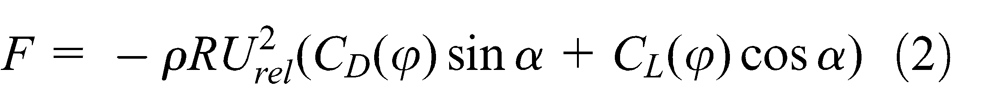
where
According to the assumptions given above, the in-plane motion equation of the cylinder can be derived as follows 21
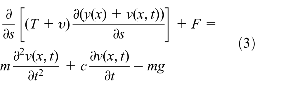
where m is the mass per unit length of the cylinder, c is the structural damping, T is the initial tension, and υ is the dynamic tension in tangential direction.
If we neglect the contribution of the longitudinal inertia term in this section, the tension along the cylinder can be handled just as the function of time. Correspondingly, the static tension H and the dynamic tension h, in axial direction, can be derived as
Equation (3) can be rewritten as

Considering that

Consequently, the dynamic tension h in axial direction can be expressed as
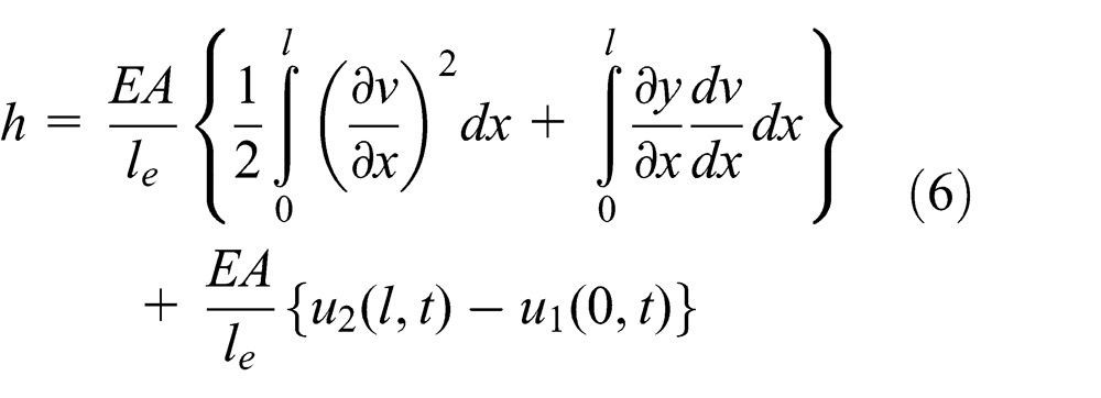
where E is Young’s modulus, A is the cross-sectional area,
Assuming that

The relative displacement of the two supporting towers at the overhead power-line ends can be derived as

where ϕ is the phase difference of the motion of two supporting towers, a 1 and a 2 are the motion amplitudes of two supporting towers, and ω 1 is the excitation frequency of the supporting towers

The dynamic tension can be expressed by
Introducing equations (4), (6), and (9) into equation (3) and taking into account the deflection at equilibrium position of overhead power-line

where
Based on aerodynamic characteristic curves obtained from wind tunnel tests, 24 the aerodynamic drag and lift coefficients are plotted in Figure 3. The aerodynamic drag and lift coefficients in equation (2) can be expressed as
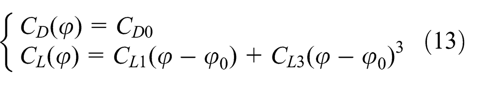
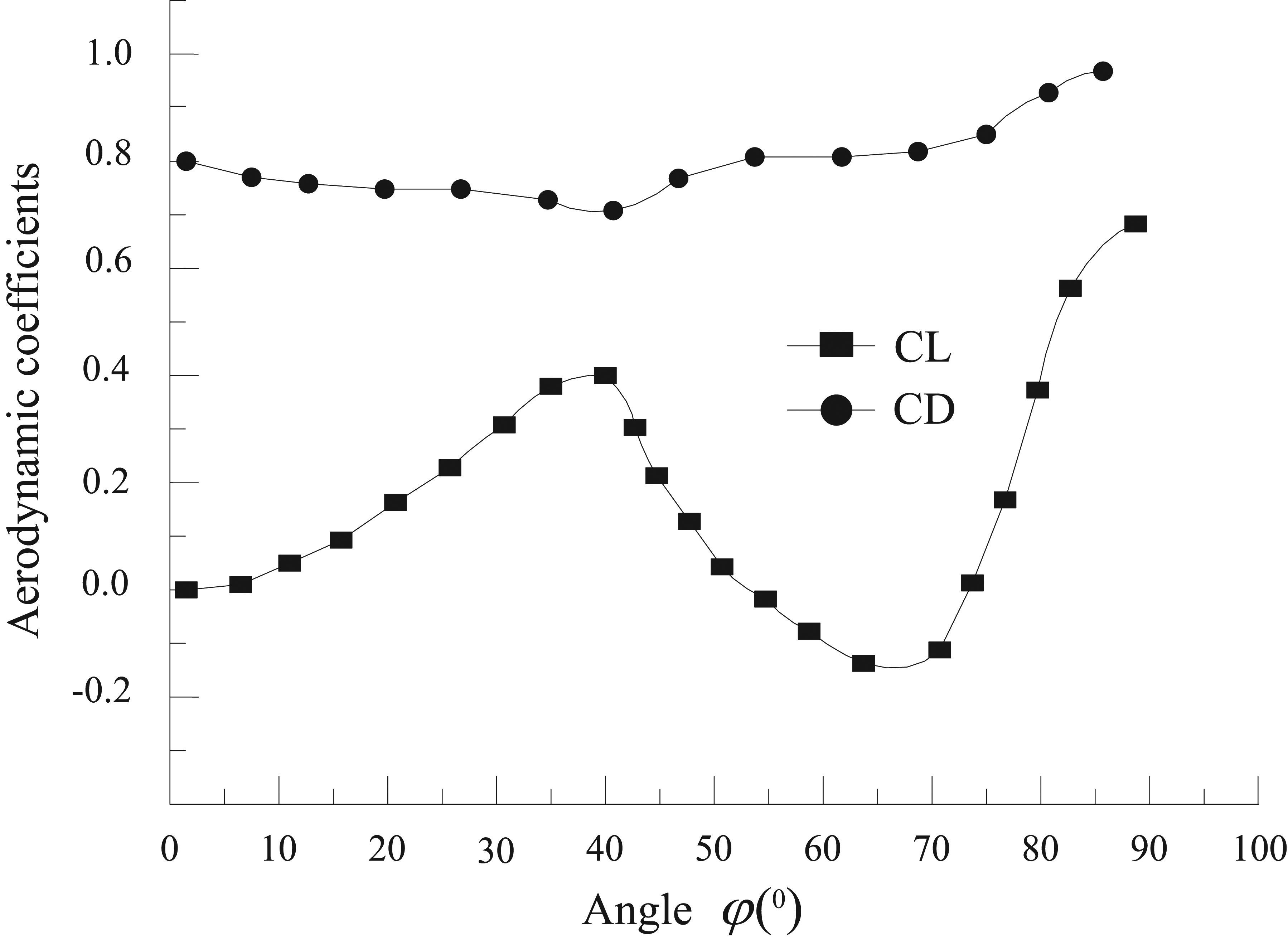
Aerodynamic coefficients versus angle φ.
where C D0 > 0, C L1 < 0, C L3 > 0, and φ 0 > 0. ϕ 0 is an angle in the domain of the φ, at which the slope of C L (φ) curve is negative, that is, C L1 < 0.
According to the test data from either filed observations or the rain–wind tunnel test of the cables in cable-stayed bridges,
15
the frequency of the upper rain-line motion is assumed to be equal to that of the overhead power-line. The oscillation range of the upper rain-line’s motion is defined as

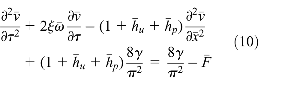
Substituting equations (13) and (14) into equation (10), the following linearized mono equation around (around
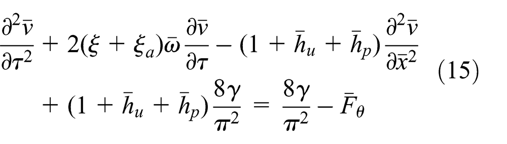
where aerodynamic damping ratio is
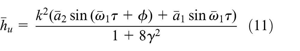
and normalized force as a result of the upper rain-line’s motion is

The boundary conditions are

Initial conditions at time
The differential equation of equation (15) in its final form can be solved by the finite element method using Galerkin method leading to a decrease in the integration order. 25 The typical element pondered residual equation can be written as follows

where

and
The integral part can be written as follows

Taking an approximate solution of the problem such that

where

where


Correspondingly, the specific expression of

where
The two derivatives can be approximated by central differences


Substituting equations (24) and (25) into equation (23) yields

By solving equation (26), it is possible to find the displacements of each node, and then each
Results and discussion
In order to validate the proposed theoretical model, the double-circuit tangent transmission tower-lines system with span of 400 m shown in Figure 4 is used in this study. For a double-circuit tangent transmission tower, 27 m in practical length and 41 m in total length, angle steel of Q235 and Q345 is used. Overhead power-line is LGJ400-35, 26.82 mm in diameter, the mass per unit length is 1.35 kg, and calculated breaking load is 103.9 kN. Ground wire is GJ-50, 9 mm in diameter, the mass per unit length is 0.424 kg, and calculated breaking load is 63.56 kN. We use the finite element software of ANSYS 12.0 to establish model of transmission tower-lines system. The towers are expressed by space beam element of beam 188 with different section areas and material properties of angle steels accordingly. The main bolts of the towers are handled as rigid connection in finite element model, while second bolts of the towers are treated as hinge joint. The overhead power-lines and ground wire are expressed by space cable element of LINK10 and hinge with the towers at specific nodes, and the insulator strings are neglected.

Double-circuit tangent tower-lines system and finite element model of the tower.
Through finite element model analysis with 0.05% damp ratio of the tower and 0.1% damp ratio of the overhead power-line (ground wire), we obtain the natural frequencies of the supporting towers and the overhead power-lines/ground wire, respectively (Table 1). Due to symmetric main structure of the tower, each order in-plane natural frequency is closer to that of out-plane natural frequency. Minor differences of natural frequencies between in-plane vibration and out-of-plane vibration of the tower may be due to the no-uniform distributed mass of tower's cross arm in vertical direction. Furthermore, we can find from Table 1 that each order in-plane/out-plane natural frequency of ground wire was higher than that of overhead power-line. This can be explained by the fact that the mass per unit length of the overhead power-line is greater than that of the ground wire.
Natural frequencies of the supporting towers and the overhead power-line (ground wire).

For the aim of obtaining the displacement responses of supporting towers in the horizontal direction, we define the simulation parameters of fluctuating wind velocity as follows: (1) the power-law exponent is 0.16; (2) the total time is 800 s, the time interval is 0.2 s, the cutoff frequency is 5 Hz, and the number of divided frequencies is 1024; (3) the horizontal fluctuating wind spectrum uses the Davenport power spectrum; and (4) the basic wind velocity V10 is 10 m/s. The total wind velocity is the sum of the mean wind velocity and fluctuating wind velocity. The wind load can be calculated 26 as

where µ is the shape coefficient, 1.34 for the tower body and 1.4 for the cross-arm,
Using the finite element software of ANSYS 12.0, the vibration response of the tower subjected to wind is then calculated. Due to the stochastic wind, the maximum displacements of tower at different heights are given in Table 2. Correspondingly, the motion amplitudes of two supporting towers a 1 and a 2 can be defined as peak in-plane displacement of tower at different heights. Furthermore, we mainly focus on the effect of supporting tower’s motion on the in-plane galloping of the overhead power-line, and the peak out-of-plane displacement and phase difference of tower at different heights can be neglected. To simplify the analysis, we only take peak displacement of tower at the height of 27 m to study the effect of supporting tower’s motion on the in-plane galloping of the overhead power-line in the following sections.
Peak displacement of tower at different heights.

Rain–wind–induced in-plane galloping of overhead power-line with fixed towers
To simplify the analysis, in this section, our research work about the aerodynamic characteristics of overhead power-line with fixed towers is first carried out. If the supporting towers were assumed to be fixed, the dynamic tension h must be equal with hp , and effect of the function of the tower’s displacement is not considered in the analysis. The in-plane motion equation of the overhead power-line becomes

Aerodynamic coefficient of
The similar results can also be obtained from the numerical results shown in Figure 5, together with experimental data. 24 Furthermore, both numerical and experimental results show that static position of θ 0 is nearly a spline function of the wind velocity U. The critical static position of θ 0 occurs within a certain range of wind velocity U, whereas the static position of θ 0 gets smaller values when wind velocity U is beyond or below this range. This is because the total damping ratio changes from a negative value to a positive value at this critical position, alternately. The aerodynamic force F gets maximum value at this critical position, while the force F will decrease quickly once wind velocity U is beyond or below this position.
Static position θ 0 versus wind velocity U.
Correspondingly, as shown in Figure 6, both analytical and experimental results imply that the largest amplitude of the overhead power-line only occurs at a certain range of wind velocity U, while beyond or below this range the amplitude just gets a small value. This is because the aerodynamic forces F can get the maximum value only within a certain range of wind velocity U, while the force F will decrease quickly beyond or below this range.
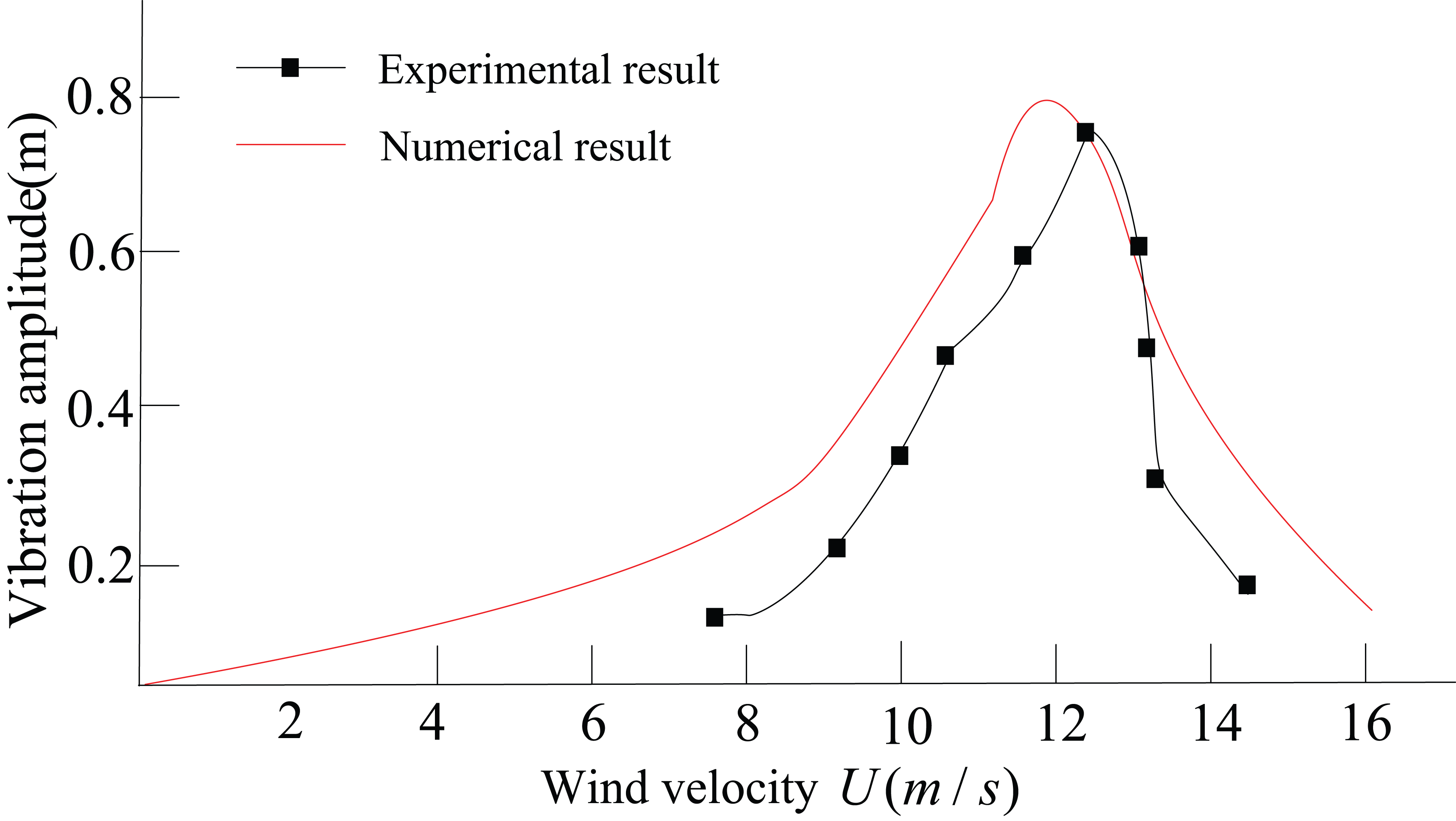
Amplitude of the overhead power-line in vertical direction versus wind velocity U.
Rain–wind–induced in-plane galloping of overhead power-line with moving towers
To analyze the validity of the proposed analytical model, the motion of the overhead power-line with moving towers is taken into consideration for predicting in-plane galloping of overhead power-line. Due to the motion of supporting towers, the total non-dimensional tension
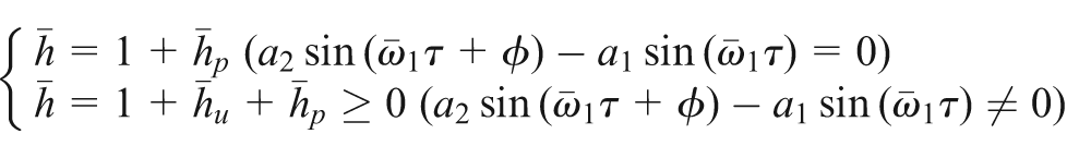
If
If
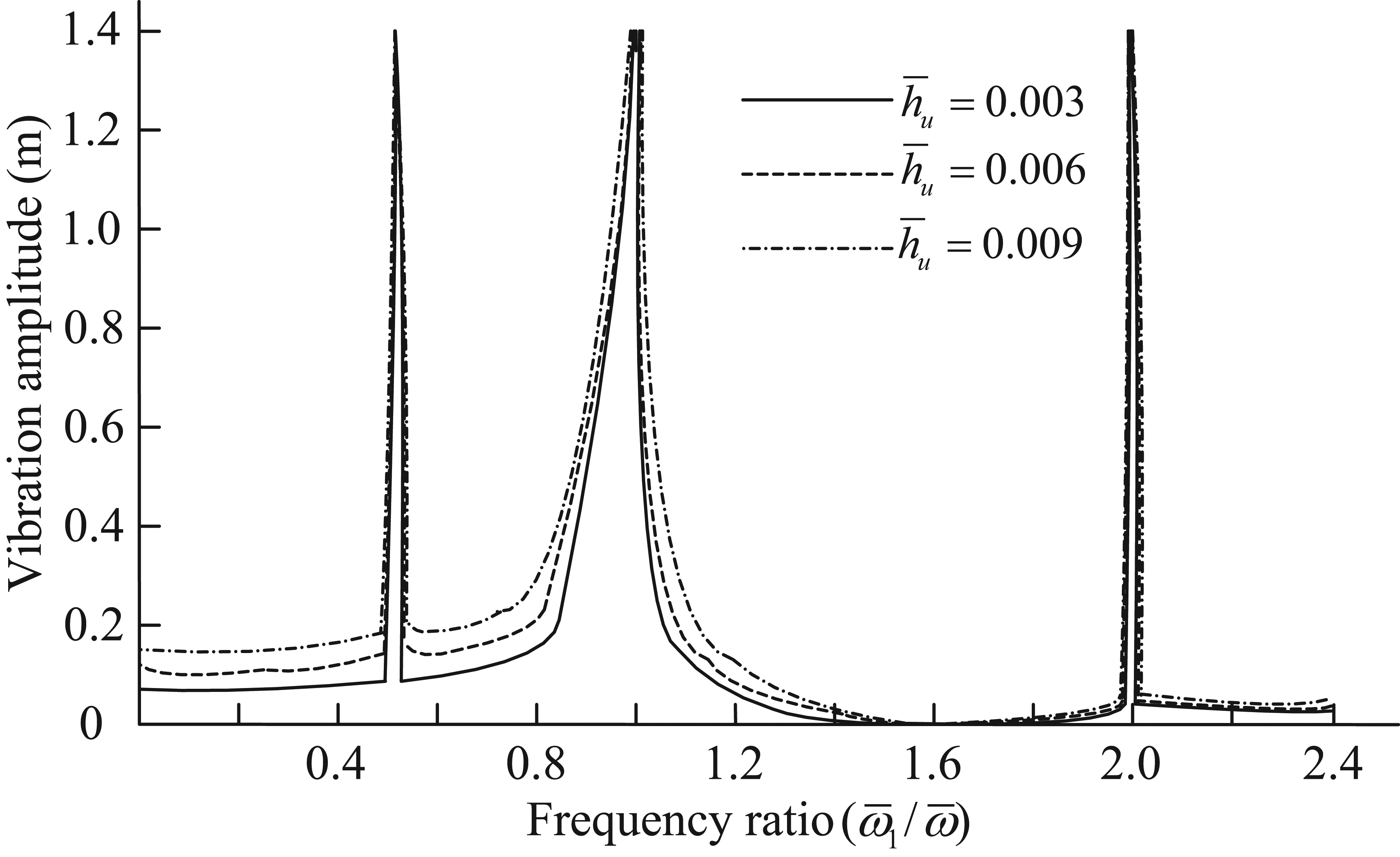
Amplitude of in-plane vibration versus frequency ratio of
The amplitude of in-plane vibration galloping of overhead power-line, at damping ratio ξ = 0.1%, U = 11 m/s, and
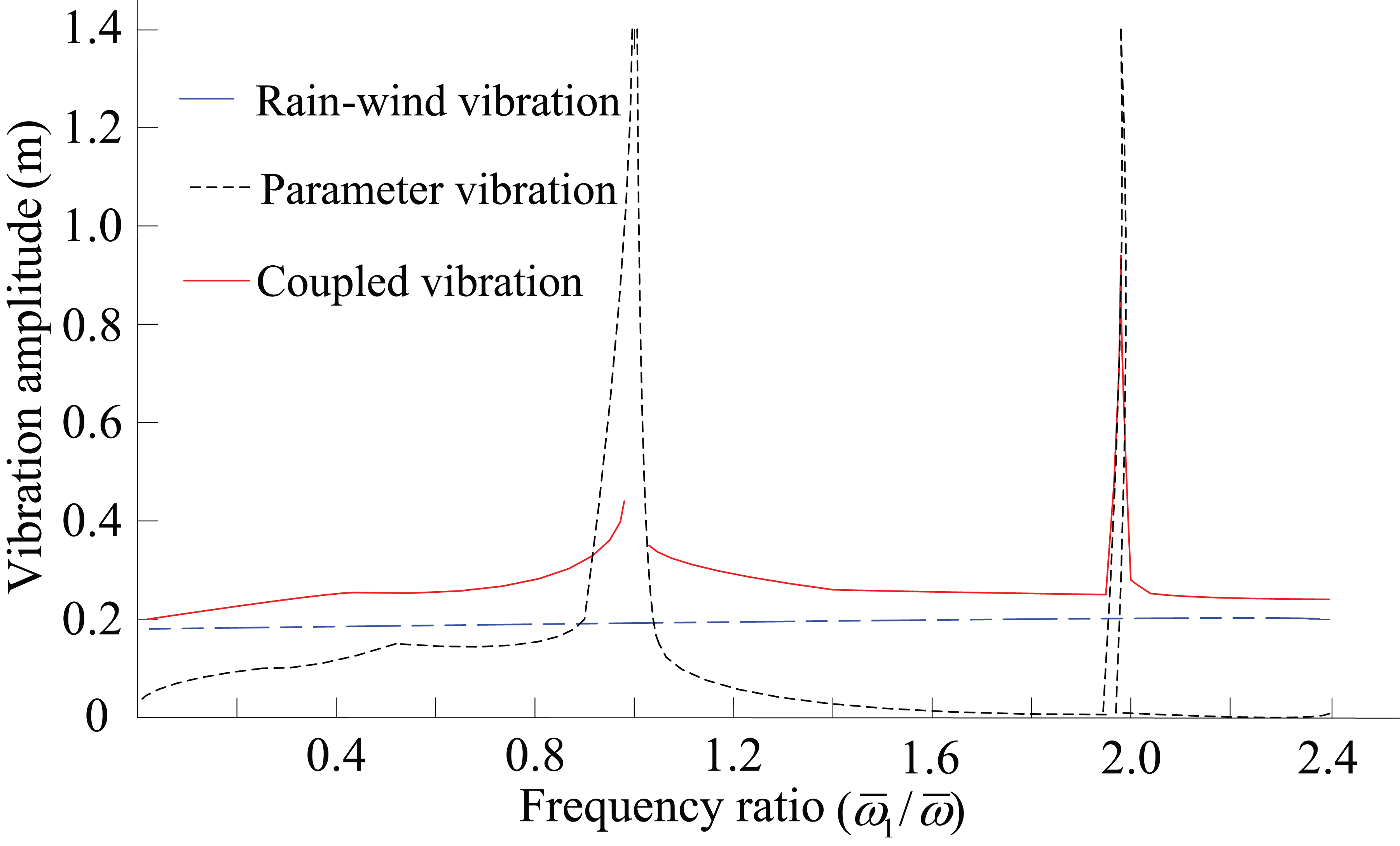
Effects of tower excitation on galloping of the overhead power-line.
To know the effect of the motion of the supporting towers on the upper rain-line, the angle response of the upper rain-line in time-domain due to the tower excitation is discussed, for damping ratio of ξ = 0.1% and frequency ratio of

Motion of the upper rain-line with the tower excitation.
The amplitude of the overhead power-line varies with different angles of the upper rain-line, for wind velocity of U = 8 m/s and frequency ratio of

Vibration amplitude of the overhead power-line versus upper rain-line.
Conclusion
Based on Galerkin method, a theoretical model of rain–wind–induced in-plane galloping of overhead transmission tower-lines system is established. The theoretical model can be used as an effective numerical analytical tool to study the mechanism of rain–wind–induced galloping with the motion of the supporting towers:
All of the numerical analytical results are in agreement with test data.
The motion of the support towers has obvious effects on the in-plane galloping amplitude of the overhead power-line.
The coupled galloping is characterized by higher amplitude, for frequency ratio range of
The coupled galloping is characterized by lower amplitude than that of the tower-excited parameter galloping at frequency ratio of
If frequency ratio of
It should be noted that the proposed analytical model is still a preliminary one. The out-of-plane motion, phase difference of the supporting towers is not taken into consideration for in-plane vibration galloping of overhead power-line in this article. Some assumptions about the model need to be revealed in the further study. More realistic wind–rain tunnels or field measurements guided by the proposed analytical model need to be developed.
Footnotes
Academic Editor: Magd Abdel Wahab
Declaration of conflicting interests
The author(s) declared no potential conflicts of interest with respect to the research, authorship, and/or publication of this article.
Funding
This project is supported by National Natural Science Foundation of China (Grant No.51575180 and No.51205128), the Beijing Natural Science Fund (Grant No.8152027) and the Fundamental Research Funds for the Central Universities (Grant No.2014ZD07).