
Abstract
This article focuses on the computing efficiency of the instantaneous cutter position error curve in computer numerical control cutter positioning, which reflects the positional relationship between the cutter and the desired surface and leads to the strip width of current positioning. The directed projection is proposed to measure the distance of a discrete point to the cutter surface. Two models using fitting techniques are established to compute the instantaneous cutter position error curve. The fitting technique used in this article is based on the quartic polynomial model. In addition, to enhance the accuracy in the nonsymmetric case, the nonsymmetric quartic polynomial model is established, and it induces a more adaptable method. Illustrated experiments show good performance of the proposed methods.
Keywords
Introduction
The optimization of cutter positioning has been a great interest for scientists in computer numerical control (CNC) machining, especially in five-axis machining.1,2 In order to estimate the adjustment, it needs to compute the envelope at current cutter positioning. However, the envelope of the cutter is unreachable in mathematics until all the positionings in a path are determined. Scientists take heroic efforts to approach the envelope. A classical idea is to measure the curvature of both the desired surface and the cutter at the cutter contact (CC) point, which focuses only on the geometric properties of one point and cost dinky in time.3–6 But the curvature-based methods commonly become unstable while the desired surface rapidly rises and falls.
Another feasible strategy is to investigate the distances between the characteristic curve on the envelope and the orthogonal curve on the desired surface. The distribution of the mentioned distances forms a curve in two-dimensional (2D) plane, and the curve is defined to be the instantaneous cutter position error curve (ICPEC). 7 The curvature-based methods are mostly carried out under the assumption that there exists only one CC point, while Warkentin et al. proposed the multi-point method (MPM) in that there exists more than one CC point to obtain wider cutting strip and enhance surface quality.8–11 As the curvature model becomes complicated in mathematics under MPM, the model of the ICPEC stably measures the positioning error under arbitrary CC points or particularly with no CC point. The ICPEC model is used to measure the strip width of cutting and to check the gouging in a given cutter positioning as described in Wang et al., 12 Xu et al.,13–16 and Yan et al. 17
A distinct drawback of ICPEC model is the low computation efficiency. The ICPEC is described by a set of discrete sample points in Li and Chen 7 and Xu et al.13–16 To acquire the sample points, it needs to measure the distances of discrete points on the cutter to the desired surface, which involves complicated computation of a point orthogonally projected onto a tanglesome surface.
Under the consideration of the simple expression of the cutter, this article measures the distances of discrete points on the desired surface to the cutter, instead of computing the distances of discrete points on the cutter to the desired surface. And the distance defined in the article is the projective distance, which is deduced from a classical method called “point-vector” commonly used in error detecting and simulation. The “point-vector” method was proposed by Chappel 18 in 1983, and the process is similar to mowing a field of grass. The key idea of the point-vector method is to intersect a vector with the cutter, while the vector starts from a point on the desired surface. In Chappel, 18 the cutter is represented by an oriented cylinder, which would cause previously unimagined error in cutter positioning optimization. The literature19,20 describes the intersection method for flat-end-, ball-end-, and fillet-end-shaped cutters in detail, but limited to the case that all the chosen vectors are parallel to the z-axis of the world coordinate system. This article decomposes a cutter into patches with simple expressions and concerns about the directed intersection for different patches.
Based on the quartic polynomial expression of ICPEC in Engeli et al., 21 this article proposed a fast fitting method to reduce the time cost of computation. The MPM pursues the existence of two CC points and supposes that the two CC points are symmetrical on ICPEC. However, the assumption is sometimes difficult to hold. Actually, it is quite common that there exists only one CC point during the process of optimization. This article overthrows the assumption of the symmetry of ICPEC and proposed a nonsymmetric model. And the number of CC points would not affect the calculation of ICPEC. In order to reduce the scale of the data set that is used for fitting, an algorithm for searching the optimal step length is established.
This article is organized as follows. Section “Directed distance of a point to a cutter” describes the directed distances of a discrete point to a CNC cutter. Section “The ICPEC” introduces the ICPEC. In section “Fast computing of ICPEC,” two methods for computing ICPEC are proposed. In section “Illustrated examples and discussions,” we give two illustrated examples. The whole article is concisely concluded in section “Conclusion.”
Directed distance of a point to a cutter
To determine the error distribution of the desired surface and the cutter, one needs to measure the distance relationship between a discrete point and a rotary surface (namely, the cutter surface). In this section, we consider the distance of a point to the cutter via a specific vector and called this distance a directed distance.
Description of CNC cutters
Only the geometry of CNC cutters is taken into consideration in the following. A CNC cutter can be treated as a rotary surface generated by its generatrix. In general, the generatrices are in the form of lines and arcs. So the cutter is the combination of cones, cylinders, and torus patches. Figure 1 illustrates the generatrices of common CNC cutters. Figure 1(a) is the generatrix of a flat-end tool, Figure 1(b) is the generatrix of a ball-end tool, Figure 1(c) is the generatrix of a torus tool, and Figure 1(d) is the generatrix of a barrel tool.

Generatrix of classical CNC cutters: (a) flat-end cutter, (b) ball-end cutter, (c) torus cutter, and (d) barrel cutter.
Directed distance of a point to a cutter
Usually, the distance of a point to a surface refers to orthogonal distance, which means the distance line between the point and the foot point is vertical to the surface (as shown in Figure 2). However, this article considers the distance that the distance line is not necessarily vertical to the surface. It is because in CNC machining, the allowance is defined to be the offset from the desired surface, not the cutter surface. So the error measure should be vertical to the desired surface, not the cutter surface. In detail, given a point


The directed distance.
Denote the above
When
The ICPEC
The process of CNC machining typically involves three surfaces, which are the desired surface, the cutter surface, and the envelope of the cutter surface. Let

is called the offset surface of
In the optimization of the cutter positioning, one needs to determine the actual effective cutting area by measuring the relationship between the desired surface and the envelope of the cutter. But inconsequently, the envelope of the cutter is unreachable before the optimization. While moving toward the cutting direction, the cutter surface instantaneously contacts the envelope at a curve, which is called the characteristic curve at current cutter positioning. The curve that the characteristic curve orthogonally projects on the desired surface is called the projective characteristic curve. To avoid the complex computation of envelope, we are trying to approach the distance between the two curves. A straightforward idea is to disperse the cutter surface and then compute the distances between the disperse points and the desired surface. Another strategy is to disperse the desired surface and then concern about the distances of the discrete points to the cutter. Since the former method involves the computation on the desired surface, which could be in high degree and complex, we follow the latter strategy. Then, the focus is transferred to the relationship between discrete points and the cutter surface.
In the rest of the section, we suppose that the driving point is
Definition 1
Denote

Usually, the cutter and the desired surface contact at one or several points. Let

The above expression of the ICPEC indicates the instantaneous positioning deviation of the cutter from the desired surface, but it is not so evident for computing the cutting strip width. Without loss of generality, suppose that the cutter cuts toward the u iso-parametric lines and the presumption holds in the rest of the article without a particular declaration. The CC points p0 and p2 satisfy

where
Equation (5) shows that the ICPEC could be approximately treated as a quartic polynomial function.
Let

to be the effective cutting interval (shown in Figure 3). The length of the effective cutting interval is called the strip width. Let

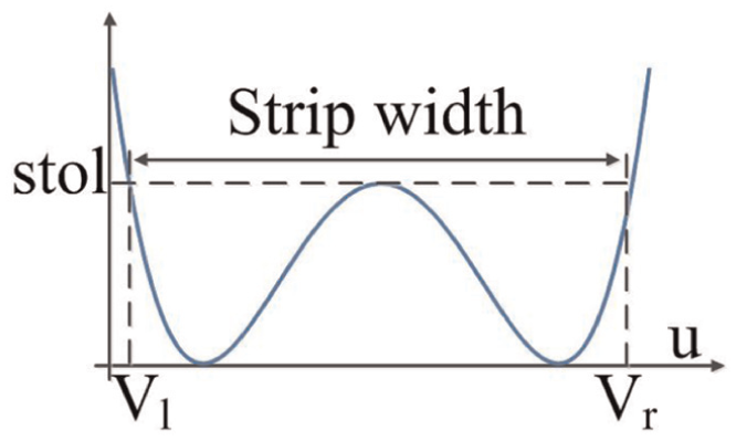
The illustration of the ICPEC.
Remark 1
If the cutter cuts toward the

Fast computing of ICPEC
In order to approach the ICPEC, one usually needs to obtain a series of sampling points located in
Symmetrical ICPEC
Let

where

Denote

By substituting

In the process of computing ICPEC, if

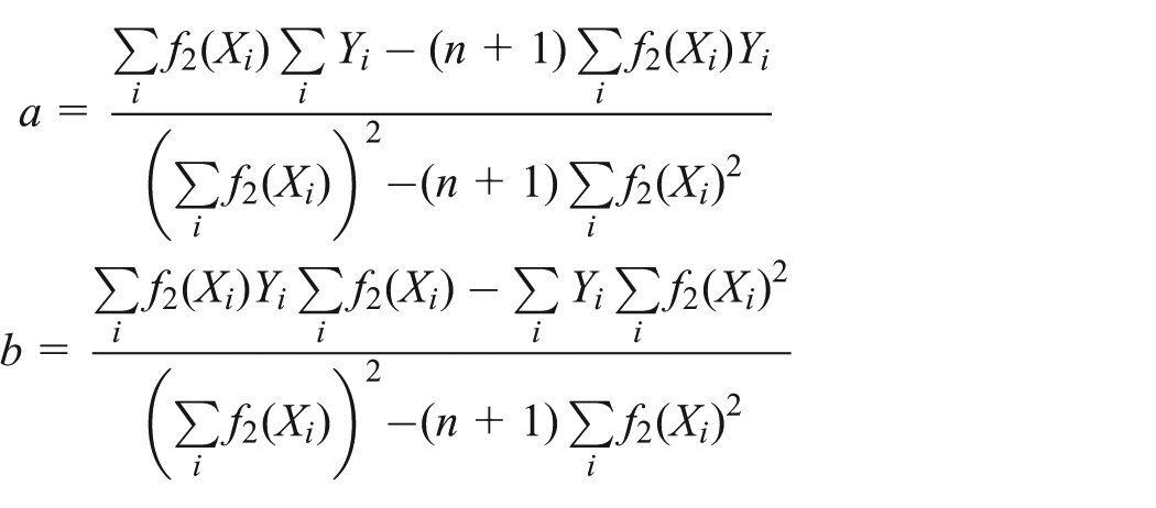
We determine a and b by following the principle of least squares. Let

Solve the optimization model

Then

It shows that one needs only to find a set of reliable sampling points in priority to determine ICPEC. And simultaneously, the scale of the data set directly affects the efficiency of the computation. We prescribe that

And there exists a constant

Remark 2
In the initial positioning of a cutter in CNC machining,
Nonsymmetric ICPEC
Since ICPEC is not always symmetric in practice, the method based on the symmetric model may lead to prodigious errors in some ordinary cases. In this section, we overthrow the symmetric assumption and establish a nonsymmetric model from two approximate CC points.
Assume that

By integration of both sides in equation (15), we have

where

x0, x1, and x2 are given, and
We prescribe that

And there exists a constant

Calculation of strip width
Once

via the root-finding formula, one can obtain four roots. Denote

If equation (18) has only one or less than one real root, then

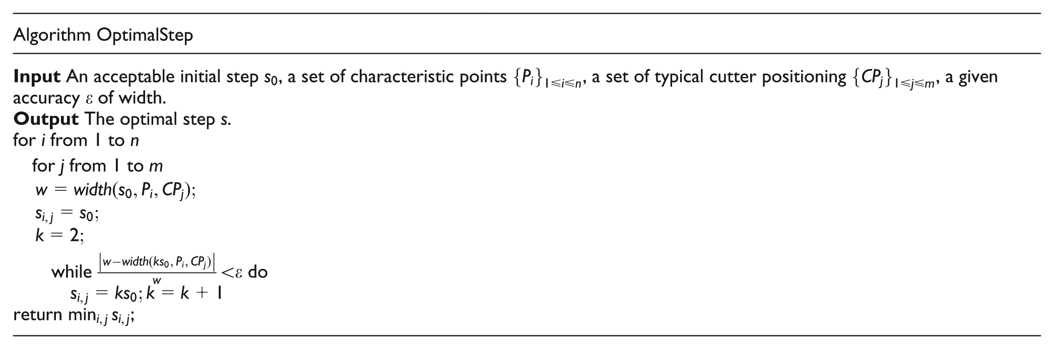
Choice of the step length
The choice of the constant
Illustrated examples and discussions
Illustrated examples
Example 1
The desired surface S is chosen to be the concave side of a cylindrical surface with radius

The desired surface for experiments.

The generatrix of the cutter for experiments.

Cutter positioning.

We have

The time cost for computing
Remark 3
The cutter positioning method has no effects on the computation of ICPEC. The middle point error control method is only used to describe the posture of the cutter.
Example 2
Example goes on under the same condition with example 1. The initial step length is set to be

where
Using the algorithm
In Figure 7, the solid circles denote the fitted points that used to approach the ICPEC, the curve is the approximate ICPEC acquired from Method 1, and the solid squares are sampling points on the ICPEC. As we can see, the curve in Figure 7(b) is fitted by only four points, while the curve in Figure 7(a) is fitted by 22 points.

Experimental results of Method 1 for Example 2: (a) using the initial step length and (b) using the optimal step length.
Similarly, the performances of Method 2 (the method mentioned in section “Nonsymmetric ICPEC”) are shown in Figure 8.

Experimental results of Method 2 for Example 2: (a) using the initial step length and (b) using the optimal step length.
For a point

The errors of the sampling points to the approximate ICPEC are shown in Figure 9. The errors of the two methods are almost equal. The average errors in Table 1 are obtained by the average errors of the points shown in Figures 7 and 8 to the approximate ICPEC computed by the two methods. And t in time cost refers to the total time cost of the method fitting the ICPEC by all the points located in
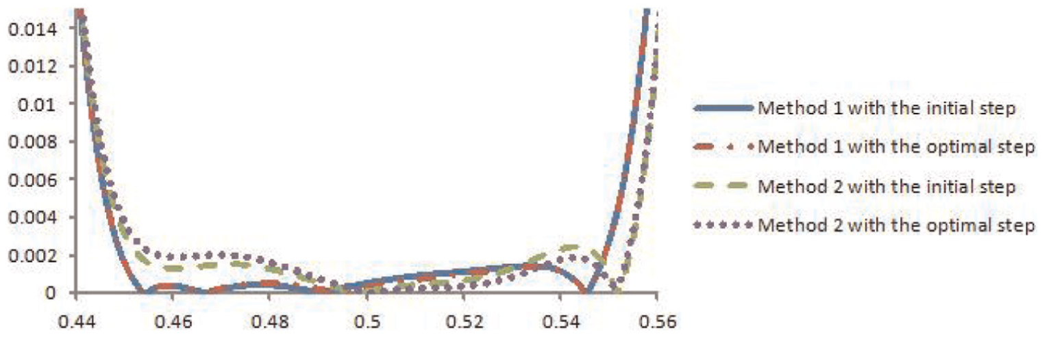
Errors of different methods for Example 2.
Performance of two methods in Example 2.

Example 3
Continue from Example 2, the inclination angle changes to
The comprehensive contrast of the performance is listed in Table 2. Figures 10 and 11 show the acquired approximate ICPEC. The numerical errors of the two methods are illustrated in Figure 12. From Figure 10, the symmetric model involves unpredictable errors, and Figure 11 shows that the proposed nonsymmetric model stably solves the problem.
Performance of two methods in Example 3.


Experimental results of Method 1 for Example 3: (a) using the initial step length and (b) using the optimal step length.

Experimental results of Method 2 for Example 3: (a) using the initial step length and (b) using the optimal step length.

Errors of different methods for Example 3.
Example 4
To verify the accuracy of the strip width estimated from Method 1 and Method 2, we check the tolerance of the path overlaps in simulating software VERICUT 6.0.3. Figure 13 shows the simulating machined surfaces with two different methods in Example 2. Figure 14 shows the simulating machined surfaces with the same cutter positioning in Example 3. The green part of the figures denotes that the tolerance is within

Simulating results for Example 2: (a) the machined surface of Method 1 and (b) the machined surface of Method 2.

Simulating results for Example 3: (a) the machined surface of Method 1 and (b) the machined surface of Method 2.
Discussions
This article first proposed the concept of directed distance, which originated from a classical method called the “point-vector method.” The orthogonal restriction is removed, and the distance calculation is turned into a line-surface intersection problem. Taking advantages of the simple expression of CNC rotary tools, the proposed strategy greatly reduces the computing time, without losing the accuracy, which is illustrated in example. The error distribution between the CNC cutter and the desired surface needs to compute the distances of the point cloud to the cutter. The less the number of points in the cloud, the less time that the computation costs. Thus, the computing time could be valued by the actual points that are involved in the distance computation. We proposed to reduce the points by two fitting models. The symmetric model works well and fast when the ICPEC is symmetric, while it involves computing error if the ICPEC is nonsymmetric. The nonsymmetric model is always effective, both in symmetric and nonsymmetric cases.
Conclusion
This article proposes two fast calculating algorithms of the ICPEC in CNC machining. Both the algorithms are based on the fitting techniques and to reduce the points involved in the distance computation. In order to accurately solve the positional relationship between the desired surface and the cutter surface, the strategy of computing the distances between discrete points on the desired surface and the cutter is used. And the directed projection is established to measure the exact distance of a point and the cutter. The experimental results show that the proposed algorithms greatly reduce the computation time under acceptable accuracy.
Footnotes
Academic Editor: Michal Kuciej
Declaration of conflicting interests
The author(s) declared no potential conflicts of interest with respect to the research, authorship, and/or publication of this article.
Funding
This work was supported by Chinese National Science and Technology Major Project 2013ZX04011031.