
Abstract
The tuned vibration absorber has become an effective device for vibration control in many engineering applications. However, using the tuned vibration absorber introduces a new resonance peak into the frequency response of the primary system and can actually increase the vibration of the primary system. We have proposed a control strategy based on variable mass adaptive tuned vibration absorber to reduce the resonance of the primary system in a previous study. However, this control plan is limited because it is difficult to obtain a key control parameter in some situations; therefore, it is difficult to implement in practical applications. Based on previous work, in this article, a simplified control strategy to reduce the resonance of the primary system with a vibration absorber attached is proposed that can easily obtain the approximation of this control parameter. A number of simulations and experiments have been carried out to test the performance of the new control plan. The results show that it is effective for reducing the resonance of the primary system with slight performance degradation of the vibration reduction, but the control parameter is much easier to obtain. The work is valuable for applications of the adaptive tuned vibration absorber on vibration control.
Introduction
As an effective device for vibration suppression, the tuned vibration absorber (TVA) 1 has been widely used in engineering fields. The TVA commonly consists of a mass that is mounted to the primary system via a spring and a damper. By tuning the natural frequency of the TVA to the excitation frequency, the primary system vibration is attenuated significantly. However, the traditional TVA can only work effectively over a narrow frequency band. When the absorber is mistuned, it becomes ineffective and can even increase the vibration of the primary system. This is the main drawback of the conventional TVA.
To widen the effective bandwidth of the absorber, the adaptive tuned vibration absorber (ATVA) has been proposed and developed in recent years.2–5 The ATVA can change its dynamic parameters to vary the absorber natural frequency, so that it can track the excitation frequency of the primary system in real time. Therefore, the ATVA can be used to suppress the vibration of the primary system subject to the excitation of time-varying frequency. The design of ATVAs to adjust the natural frequency includes changing the number of active coils of a spring by Franchek et al., 6 varying the pressure of an air spring which is applied as the stiffness element of a dynamic vibration absorber by Jin et al., 7 using smart materials, such as shape memory alloy by Williams et al. 8 or magnetorheological elastomer by Deng and Gong, 9 and using variable mass by Gao et al. 10 The control strategy for ATVA is also an important topic in absorber study fields. Most researchers have formulated the vibration control problem by adjusting the ATVA stiffness as a parametric control problem. Because the stiffness term of the ATVA enters the control objective function in a complicated nonlinear way, this parametric control problem can also be viewed as a nonlinear optimization problem. 3 Ryan et al. 11 tuned an ATVA using a classical linear control method of proportional gain feedback and proved its effectiveness via experimental test. Williams et al. 12 proposed a nonlinear controller for a shape memory alloy ATVA to deal with the saturation of the material by incorporating a developed antiwindup algorithm. Long et al. 13 and Brennan et al. 14 combined two traditional control algorithms to solve the absorber tuning problem. In this method, a rough algorithm was first used to look up a table to roughly get the required stiffness for a given excitation frequency and then a fine-tuning algorithm based on the steepest descent method was used to improve the control precision. Artificial intelligent methods are also applied to ATVA control. Lai and Wang15,16 proposed a heuristic method using fuzzy logic to control the ATVA and theoretically analyzed its features. The neural network control is suitable for solving the nonlinear control problem, and DiDomenico 17 suggested a neural network–based controller to tune the ATVA and suppress the vibration of the primary system.
Many studies focused on controlling the ATVA to precisely track the time-varying excitation frequency have been conducted so far. However, to the best of our knowledge, control strategies to prevent the absorber from increasing the vibration of the primary system when it is mistuned have seldom been reported in the literature, although some works have indicated that the vibration increase can be attenuated by optimizing the damping value of the absorber in the design stage.18,19 The authors of this article have proposed a control strategy based on variable mass ATVA to prevent the ATVA from increasing the vibration of the primary system in a previous work. 20 Simulation and experiments verified that the control strategy works effectively. Nevertheless, this control plan experiences difficulties when it is implemented in practical engineering applications of vibration control since a control parameter is difficult to be obtained in some situations. To deal with this problem, a simplified control plan is suggested, and its performance is measured in this article.
This article is organized as follows: After introduction, the old control strategy for the ATVA to reduce the resonance of the primary system is described, including the principle for the variable mass and variable stiffness ATVA. Then, the simplified control strategy based on the variable mass ATVA is presented. In the following section, experiments verifying the new control plan are given, and some conclusions are drawn in the final section.
Control strategy for ATVA to reduce primary system resonance
The main defect of a conventional vibration absorber is that the vibration of the primary system can increase when the absorber is mistuned.3,4 The reason is that the system becomes a two-degree-of-freedom system when an absorber is attached to a primary system. Therefore, the new system has two natural frequencies, which can be calculated as follows when the damping is neglected 21
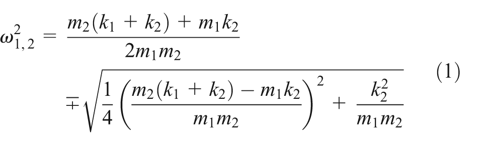
where

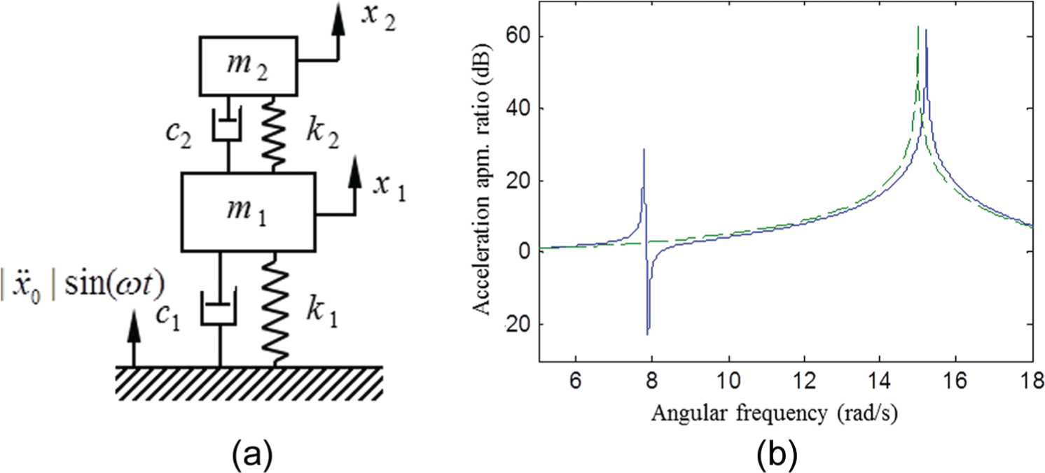
(a) Application of a TVA to a primary system and (b) frequency responses of the primary system.
where
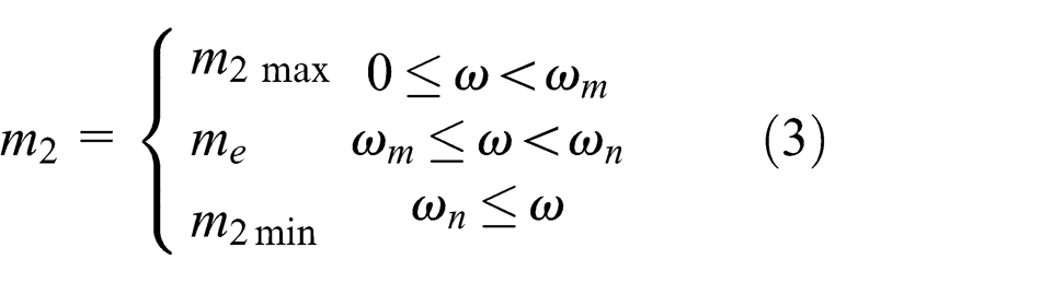
where a variable mass ATVA model is used, as shown in Figure 2(a). Here,
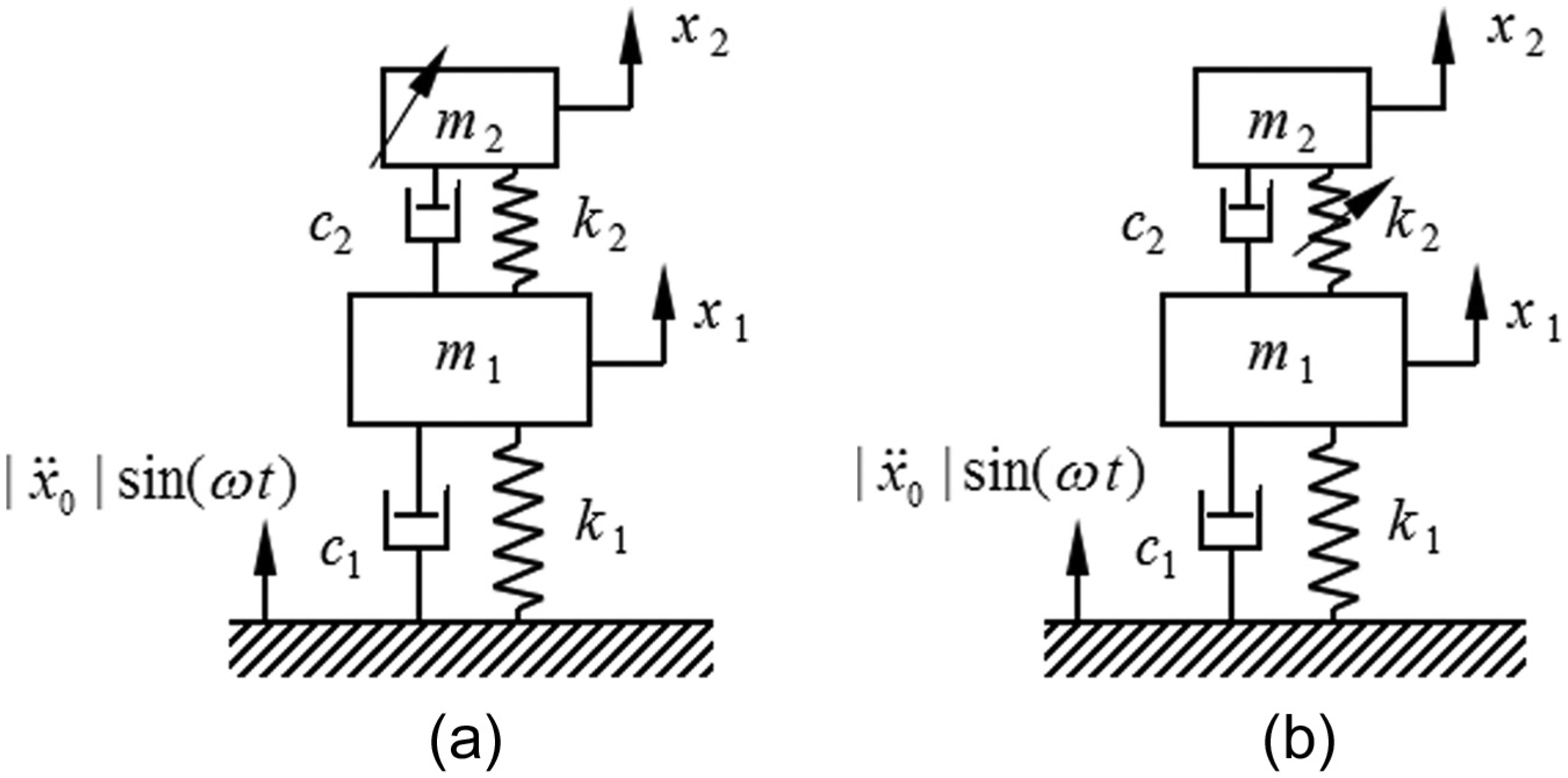
Application of an ATVA to a primary system: (a) variable mass ATVA and (b) variable stiffness ATVA.

Frequency responses of the primary system with a variable mass ATVA attached.
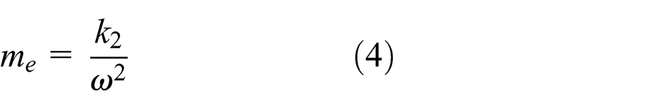
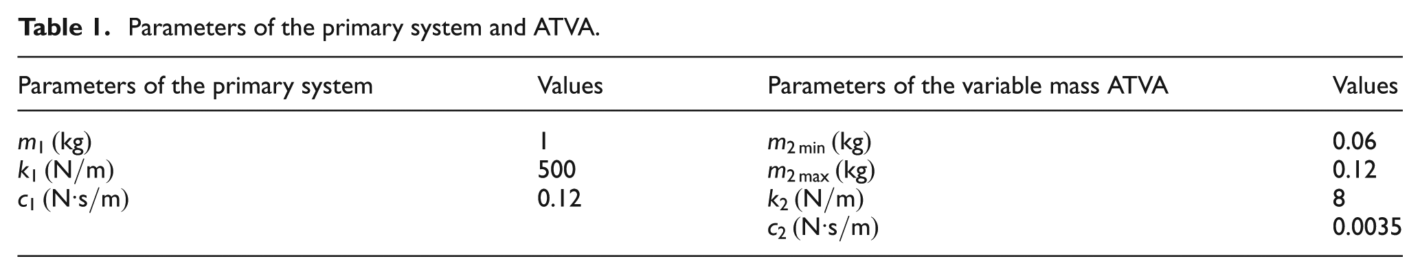
Numerical simulations were conducted to specify this control plan. The parameters of the primary system and the variable mass ATVA used in the simulations are listed in Table 1. Laplace transformation was used to calculate the frequency responses of the primary system when the variable mass ATVA achieved its minimal and maximal masses since the system was a linear time-invariant system under these two conditions. The two frequency responses are illustrated in Figure 3. When the ATVA changed its mass to match the excitation frequency, which satisfied the condition of

where
Parameters of the primary system and ATVA.

Frequency responses of the primary system with a variable mass ATVA attached.
From the discussion above, one maybe notice that the variable mass ATVA is not the essential condition of this control plan, in fact the variable mass ATVA is just a case to explain the control algorithm. The control plan can actually be generalized and used to control other types of ATVA, for example, ATVA based on variable stiffness. When the variable stiffness ATVA is applied, the control plan can be formulated as

where
Simplified control strategy of resonance reduction
Simplified control strategy
As was mentioned above, a high-performance ATVA with wide bandwidth and more stability can be obtained by applying the control strategy formulated as equation (5). However, the control plan is sometimes impractical in vibration control applications. As the most important parameter of the control plan, the frequency of point S, that is,


Frequency responses of the primary system with a variable mass ATVA attached.
where the variable mass model is applied. It can be seen that different from the previous one (equation (5)), in new control plan, the variable mass keeps the minimal value while the excitation frequency is less than
Simulation of the control plan
The performance of the new control strategy was investigated via a number of numerical simulations, whose parameters are listed in Table 1. The simulations were carried out in MATLAB environment. Laplace transformation was applied to compute the frequency responses of the primary system when the variable mass ATVA obtained its maximal and minimal masses. The frequency responses are presented in Figure 5. We can clearly see that the primary system vibration is attenuated by 13.32 and 9.62 dB at the frequencies of 8.17 and 12.65 rad/s, while the variable mass obtains its maximal and minimal values. When the excitation frequency was in the range from
Responses of points P, S, T, and M.

Experimental verification
Experiments were conducted to validate the performance of the proposed control strategy. Figure 6 shows the experimental system, in which the primary system was composed of a cantilevered beam made of stainless steel (working as the stiffness element) and two lumped mass with a vibration acceleration sensor attached (working as the primary system mass). The lumped mass and the acceleration sensor were fixed at one end of the cantilever beam, where the variable mass ATVA was also mounted. The other end of the cantilever beam of the primary system was clamped on the top of an electromagnetic shaker. The variable mass ATVA was composed of a steel sheet acting as the stiffness element and a plastic tank acting as the variable mass. Water was used as the working medium to vary the absorber mass. The primary system was excited by the electromagnetic shaker, which was controlled by a signal generator and a power amplifier. The vibration acceleration of the base of the primary system was measured by another sensor to obtain the vibration input.
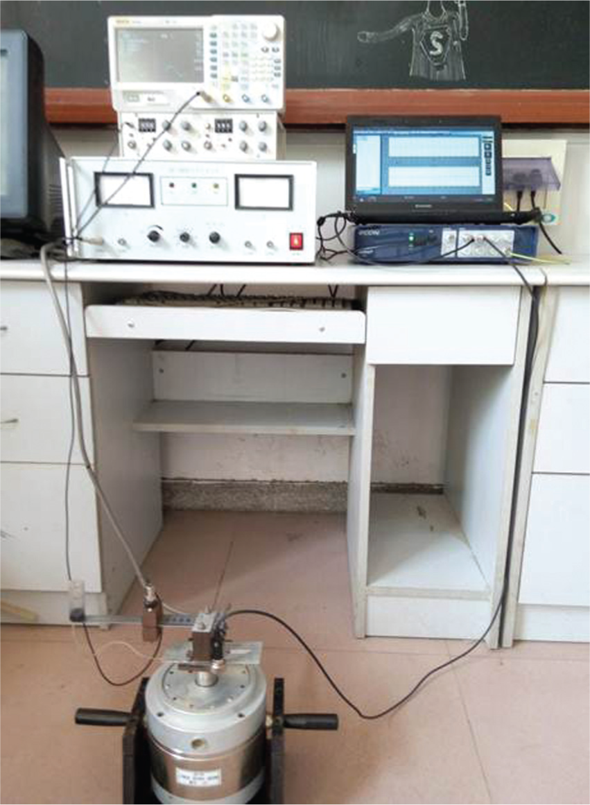
Experiment system.
In the experiments, the excitation was accomplished using a sine input with the amplitude of 1.00 m/s2 and stepped frequency. The frequency response of the primary system was computed using equation (2) when the ATVA obtained its different mass, with the acceleration of the primary system mass as the output signal. Figure 7 shows the frequency responses of the primary system, while the plastic tank was empty and filled with water. It can be seen that the vibration of the primary system can be reduced by 13.87 dB at the frequency of 11.41 Hz when the plastic tank is filled with water and 13.12 dB at the frequency of 14.92 Hz when the tank is empty. To obtain more information about the absorber, experiments were also conducted when the plastic tank was filled with one half water approximately, and the frequency response of the primary system was recorded. Using the control plan in equation (3), the variable mass ATVA can significantly reduce the primary system vibration over the frequency range from 11.41 to 14.92 Hz by adjusting the absorber mass. However, the primary system vibration increases using this plan when it is working at point P, where the vibration amplification ratio is 18.30 dB, as shown by the green line in Figure 8. The frequency responses of the primary system are also presented in Figure 8 when the simplified control strategy and the plan in equation (5) are used. We can see that the host vibration is amplified by 5.08 dB at 11.41 Hz (point T) when the new control strategy is used, and it is suppressed by 13.22 dB compared with the amplification ratio at point P. Nevertheless, the amplification ratio at point S is 4.63 dB. This implies that the amplification ratio at point T increases by about 0.45 dB compared with that at point S. The frequencies of points S and T are 11.11 and 11.41 Hz, respectively, then the decrease in the ATVA bandwidth, which is the difference between the upper and lower cutoff frequency of the absorber, is less than 0.30 Hz. Vibration acceleration of the excitation signals and the responses of the primary system at points P, S, T, and M were measured in experiments, as shown in Figure 9. We can see that while the excitation amplitude is 1.00 m/s2, the acceleration amplitude of the primary system at point S is 1.70 m/s2; meanwhile, at point T, this is 1.79 m/s2. The latter is 5.29% more than the former (Figure 9(a) and (b)). The acceleration amplitude at point M is suppressed to 20.25% of the excitation since the ATVA is tuned under this condition (Figure 9(d)). The primary system resonates at point P, so that the vibration amplitude is magnified 8.82 times. The resonance can be prevented by using the proposed control strategy; however, the vibration reduction performance of the ATVA slightly degrades. The advantage of the control plan is that it is much easier to be implemented in practical applications. This is very valuable in engineering vibration control.

Frequency responses of the primary system with a variable mass ATVA attached.

Frequency responses of the primary system with a variable mass ATVA attached.

Vibration acceleration measured in experiments. : excitation; (a)  : response of the primary system at point S; (b)
  : point T; (c)
  : point P; and (d)
  : point M.
Conclusion
In this article, a simplified control strategy to suppress the primary system resonance was proposed. This strategy is based on a previous study in which a control plan based on variable mass ATVA is suggested to widen the effective bandwidth of the ATVA, while avoiding the resonance of the primary system. Nevertheless, a key control parameter of the previous control plan is difficult to acquire, so it cannot be implemented in some practical applications. In this simplified control plan, an approximate control parameter that is easy to obtain is suggested to replace the old one. The results of our simulation and experiments show that the new control strategy slightly narrows the effective bandwidth and degrades the vibration reduction performance of the ATVA, but the control parameter is easy to obtain. The latter is useful to apply the control plan to practical applications.
Footnotes
Academic Editor: Sang-Wook Kang
Declaration of conflicting interests
The author(s) declared no potential conflicts of interest with respect to the research, authorship, and/or publication of this article.
Funding
The author(s) disclosed receipt of the following financial support for the research, authorship, and/or publication of this article: This study was supported by the National Natural Science Foundation of China (Nos. 51175049 and 51275380) and the Special Fund for Basic Scientific Research of Central Colleges, Chang’an University (CHD2012ZD007).