
Abstract
Traffic delays are caused by unskilled vehicle operation and driver distraction during the startup process at signalized intersections. To address this issue, we propose a V2I-based driver assistance system that can acquire the current traffic signal status and provide drivers with startup assistance. This article presents the proposed system’s architecture and an assistance algorithm, which contains two types of driver assistance methods: startup prompting and automatic startup control. The automatic startup control method, based on fuzzy logic control, is validated in simulation tests. We also implement startup prompting using a prototype system and validate its performance in field tests. The test results suggest that the proposed assistance algorithm can help drivers start up their vehicles with less delay, which will significantly improve traffic efficiency.
Introduction
In recent years, there has been a growing focus on improving traffic efficiency at intersections, and one research focus has been the delay in vehicle startups. According to the stimulus–response model, 1 the perception–reaction model, 2 and other general car-following models,3–5 variations in driver reaction times when starting up their vehicles in a discharged queue are inevitable. With unskilled drivers, there is a longer delay in the start time to pass through an intersection after the preceding vehicle has moved.
To date, many studies have been conducted with respect to intersection traffic efficiency, including the analysis and estimation of queue delays and driver behavior at intersections. Queue diffusion properties with and without countdown timers have been studied in heterogeneous traffic conditions, and results have shown that mounted timers can reduce startup delays. 6 In other research, an algorithm was developed to classify and estimate driver behavior at intersections. 7 Road user behavior when crossing intersections, including motor vehicle, nonmotor vehicle, and pedestrian users, has been statistically established, 8 while some researches focus on driver behavior at unsignalized intersections.9,10 An analysis of vehicle platoon starting features has also provided evidence to explain the fact that longer startup delays lead to reduced traffic efficiency at intersections. 11
To reduce vehicle traffic delays in a platoon and enhance intersection traffic efficiency, driver assistance systems specific to intersection conditions are necessary, and a number of systems have been proposed. 12 One such system is a collision prediction algorithm for unsignalized intersections that utilizes road map data. 13 In a different study, a cooperative ecological driver assistance system (EDAS) was developed to predict vehicle-road-traffic states. 14 Based on V2X technology, 15 research on intersection safety and efficiency assistance systems has been conducted, including systems that inform and warn drivers and that offer other intervention functions. 16 An on-board traffic light assistant (OTLA) system has been proposed, which is also based on V2X wireless communications. 17 OTLA assists drivers to enhance their response to incoming events by offering a predicted forthcoming traffic light phase. An intersection driver assistance system (IDAS) has also been developed, which uses received information regarding traffic signal status to provide efficiency-increasing passing support to drivers. 18 However, these assistance systems concentrate solely on adding a stimulus to enhance driver response. This means that relatively long driver delays are still inevitable. Proper vehicle control technologies can facilitate the enhancement of intersection traffic efficiency. 19 Stop-and-go (S&G) systems have been shown to effectively adjust the relative distance between the ego vehicle and the preceding vehicle in S&G driving situations. 20 However, drivers of vehicles equipped with S&G systems in the vehicle platoon cannot be informed about the whole platoon’s behavior in advance, as it only uses data collected by speed and distance sensors. Autonomous vehicle control for the purposes of intersection management to reduce driver delay and avoid potential crashes is another concept that has been presented. 21 One such proposal for intersection management uses cooperative adaptive cruise control (iCACC) to reduce the driver delay and avoid potential crashes. 22 The simulation results of acceleration or deceleration maneuvers show that iCACC improves intersection traffic efficiency to a great extent with respect to defined efficiency indices.
In this article, we propose a driver assistance system based on V2I communication technology that is intended to help every vehicle acquire traffic light information and implement specific assistance strategies to help vehicles start with less delay time. The development of this system required a series of related tasks. First, we defined the function of the system and then designed its architecture. We then developed a driver assistance algorithm and conducted simulation tests of the automatic startup control method. Finally, we performed field tests to validate the function of a prototype system that can provide startup prompting to drivers.
System architecture configuration
Definition of system function
The type of driver assistance system we focus on in this study is one that offers assistance to drivers queued for a traffic light to start up their vehicles simultaneously when the traffic light switches to green. The vehicles then form a platoon and pass through the intersection quickly to reduce startup delays.
The system consists of two parts, the roadside unit (RSU) and the on-board unit (OBU). The OBU collects traffic signal phase and timing information from the RSU, to assist drivers to start up their vehicles at the moment when the signal switches to green. Drivers can choose to start up their vehicles manually or to engage automatic vehicle startup control.
System architecture
As defined in the section above, Figure 1 illustrates the design of the system architecture.
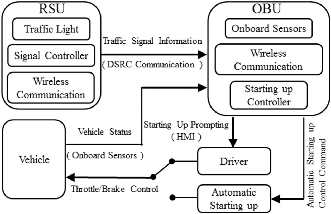
System architecture.
In this system, the RSU is a traffic light equipped with a wireless communication device that can broadcast current signal phase and timing information to vehicles approaching the intersection. The OBU consists of three parts: (1) on-board sensors collect data on the current state of the controlled vehicle, including its velocity, acceleration, and following distance to the preceding vehicle; (2) a wireless communication device collects traffic light information from the RSU; and (3) a startup controller, based on vehicle S&G cruise control, starts up the vehicle automatically while keeping a safe distance from the preceding vehicle. Drivers can choose to start up their vehicles manually or by automatic vehicle startup control. Figure 2 shows the OBU layer configuration according to the system architecture.

OBU layer configuration.
Driver assistance algorithm
Vehicle startup model
To evaluate the time delay, we propose a model to simulate the startup process of vehicles, based on the following assumptions and definitions:
A simplified vehicle acceleration process is used, with a uniform acceleration process. The duration of the acceleration process is ta . After acceleration, vehicles run at a constant velocity v 0.
The time delay from the time the traffic light turns green to when the first vehicle in the queue starts to accelerate is Δt 1. The time delay from the time a preceding vehicle starts to accelerate to when the rear vehicle starts to accelerate is Δt 2.
The distance headway between vehicles stopped in the queue is l 0. The average vehicle length is d 0.
Figure 3 shows the spatial relationship of vehicles during the startup process. Figure 4 shows the velocity curves during the startup process.
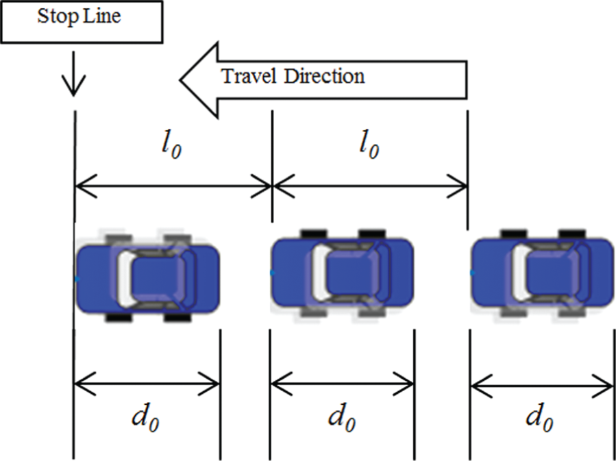
Spatial relationships during the startup process.

Velocity curves during the startup process.
Based on the assumptions and definitions above, when two adjacent vehicles have accelerated to constant velocity v
0, the distance headway becomes

The number of vehicles in the queue is denoted as N. When all the vehicles in the queue have stopped, the length of the queue is l 1

When all the vehicles have accelerated to constant velocity v
0, the length of the queue is

The time it takes for all the vehicles to pass the stop line is denoted as td (assuming that when the last vehicle passes the stop line, the velocity has accelerated to the constant velocity v 0)

in which


From the expression of td , we know that the time delay mainly consists of td 1 and td 2. The first value, td 1, is influenced by the vehicles’ acceleration, velocity, and length, as well as the initial distance headway of the vehicles. The second value, td 2, is mainly influenced by the values of N and Δt 2, as well as that of Δt 1.
The value of Δt 2 can be estimated using the traffic monitoring data. Here, the duration of the vehicle startup process is denoted as t, and the corresponding displacement of the vehicle is denoted as s. According to the assumptions above, s can be formulated as

So, the interval between the times when the first and the nth vehicle in the queue pass the stop line, which is denoted as tD , can be formulated as

in which f −1(s) is the inverse function of f(t), and here s = (n − 1)l 0 represents the displacement of the nth vehicle, and ta corresponds to the tD of the Na th vehicle. Then, tD can be expressed as a piecewise function of n. Based on this formula, we applied the linear least squares fitting method to estimate the value of Δt 2, using traffic monitoring data. These data were collected at a signalized intersection with medium traffic flow and recorded the time intervals tD and the corresponding ordinal number of vehicles n. In the fitting process, we change the threshold Na from 1 to 14 (the maximum vehicle number) to piecewise fit the function of tD (n) in a least squares sense, as well as guarantee the physical meaning of each coefficients. According to the fitting result shown in Figure 5, the estimated value of Δt 2 was 1.48 s.
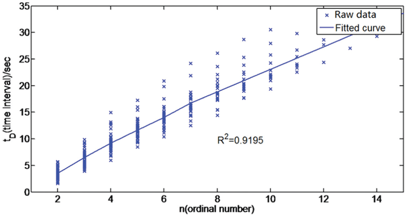
Least squares fitting result.
From the td 2 values, we see that there is a positive linear relationship with N, so the cumulative impact of the time delay Δt 2 will increase with increase in N. Therefore, if we can reduce the td 2 time delay by reducing the Δt 2 time delay, the total time delay td will also be reduced, especially in scenarios where the number of vehicles in the queue is very large.
Driver assistance algorithm
The driver assistance algorithm is shown in Figure 6.
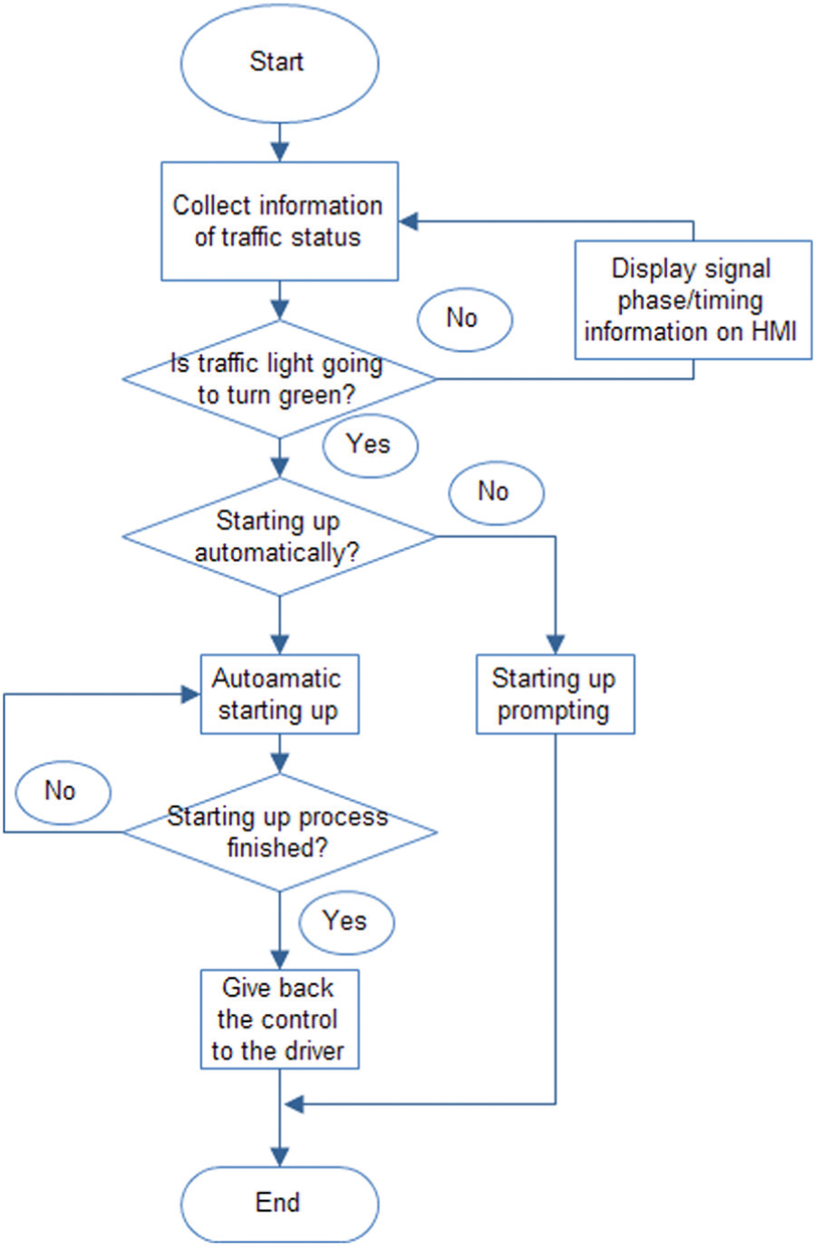
Driver assistance algorithm.
Traffic light information is collected by the RSU communication devices, and when the traffic light switches to green, startup assistance is available to drivers to help start up their vehicles. To this end, we propose two types of assistance methods with respect to the automation level. The first method is to provide startup prompting to the driver before the traffic light turns green, and the second method relies on automatic control to help the driver start up the vehicle.
Startup prompting
To prompt drivers, the traffic signal status (signal phase and time) is communicated to each vehicle in real time by the traffic signal controller when vehicles enter the communication range. If the current traffic signal is green, no prompt will be delivered. If the current signal is red and the vehicle has stopped, the startup prompting system will be activated. When the time remaining in the red phase is less than a preset threshold, which is denoted as Tr , an acoustic prompt to count down the remaining time will be delivered to the driver. Thus, the driver can prepare for startup in advance. The startup prompting system works like a traffic light countdown timer but is more practical because prompts are sent to all drivers within range, rather than only a few drivers in the front of the queue. Thereby, all drivers are assisted to prepare for startup.
Automatic startup control
In the proposed system, we designed a fuzzy logic controller to develop the automatic vehicle startup system. Fuzzy logic is an artificial intelligence technology that is used to mimic human behaviors such as fuzzy reasoning and intuitive decision-making. Compared with the conventional control methods used in adaptive cruise control (ACC) or S&G control systems, such as model predictive control (MPC) and proportional–derivative (PD) controllers, fuzzy control operates more like a human driver and thus is a feasible method for use in vehicle startup control.
We based the development of the fuzzy controller in this study on a simple second-order model of vehicle dynamics 23 with a time-delay term, and the resulting speed response model is as follows

where k, θ, ωn , and Td are the static gain, damping ratio, inherent frequency, and time delay, respectively.
In the controller, the velocity of the preceding vehicle is set as the reference velocity, while the distance error, velocity error, and acceleration error form a feedback loop to modify the final desired velocity. The block diagram of the proposed controller is shown in Figure 7.

Block diagram of the controller.
In Figure 7, ΔD denotes the difference between the desired inter-vehicle distance and the actual inter-vehicle distance, which are denoted as ddes and da , respectively. As such, ΔD may be represented as follows

Here, a constant distance headway policy is applied to achieve a relatively short startup delay, so we assign the desired inter-vehicle distance ddes to be a constant value of 7 m.
ΔV and ΔA in Figure 7 denote differences between the two vehicles’ velocities and accelerations, and they can be expressed as follows

where vp and ap are the velocity and acceleration of the preceding vehicle, respectively, and vf and af are those of the follower vehicle. As depicted in Figure 7, ΔV and ΔA act as fuzzy controller inputs to generate feedback for the reference velocity, which is denoted as Vref , and the final output of the controller is desired velocity, which is denoted as Vdes .
The fuzzy controller contains three functional modules: (1) a fuzzification module, which transforms the numerical inputs into linguistic values; (2) a fuzzy logic inference module, which generates linguistic results based on predefined rules; and (3) a defuzzification module, which transforms the linguistic values into numeric outputs. The proposed fuzzy controller is a Mamdani type, and in the defuzzification process, output is gained using the center-of-area method. The membership functions of the input and output variables are illustrated in Figure 8, and the inference rule base is shown in Table 1.
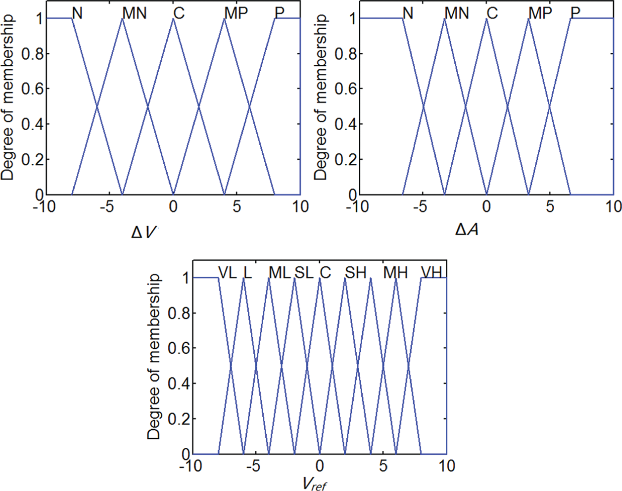
Membership functions.
Inference rule base.

In the automatic startup controller, the key point is the adjustment of the four gain values ki 1, ki 2, ki 3, and ko , which directly affect the performance of the controller. To this end, the four parameters are tuned manually to pursue a satisfying response to a step input signal, during which the response rate, overshoot, and steady-state error are taken into consideration. We found the best fit parameters to be ki 1 = 30, ki 2 = 10, ki 3 = 1.3, and ko = 1.
Simulation results
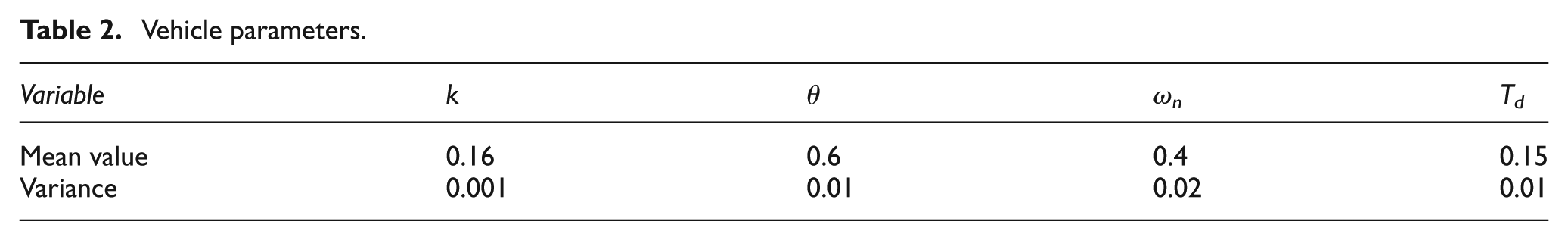
To evaluate the performance of the proposed automatic startup controller, we next carried out simulations. To emulate the startup process, only low-speed situations were considered. In the simulation, a total of five vehicles are queued and waiting for the traffic light to change. The length of each vehicle is 4.5 m. To model differences in the vehicle dynamics, the variables k, θ, ωn , and Td for each vehicle follow a Gaussian distribution, as shown in Table 2.
Vehicle parameters.
For the purposes of comparison, we also considered a linear quadratic (LQ)-based ACC controller 24 in which the LQ controller follows a constant time headway (1.48 s) policy—a policy often followed in actual ACC products. Note that the acceleration transfer function is the same as that of velocity, so the above vehicle model is also feasible for an LQ controller, and the LQ controller will generate the desired acceleration to control the vehicle. Figure 9 illustrates the simulation results.

Simulation results (left: fuzzy controller; right: LQ controller).
In the simulation, five vehicles stop in a queue with an equal inter-vehicle distance of 3.5 m. The first vehicle then starts up from being still, follows a reference velocity profile, and the other vehicles follow the preceding vehicles in starting up. From the acceleration profiles, we can conclude that the fuzzy controller requires a higher acceleration than the LQ controller. This corresponds to the fast velocity response rate of the fuzzy controller, as shown in the velocity profiles. With the fuzzy controller, the velocities of the vehicles increase quickly, tracking the reference velocity profile, and all the vehicles accelerate to the reference velocity by 10 s, thus shortening the startup process. Compared with the fuzzy controller, the velocity profiles of the LQ controller share the same growth rate and keep a constant time clearance. This obviously leads to a longer startup process. However, there is a trade-off between the response rate and stability. As shown in the velocity profiles, the fuzzy controller has a relatively high velocity overshoot, while the LQ controller has almost no overshoot.
The effect of reducing the startup delay of the proposed controller is clearly shown in the displacement profiles. Using the fuzzy controller, it takes 10.09 s for the fifth vehicle to pass the stop bar, while the time is 16.97 s when using the LQ controller (values in Figure 9 are greater than those in Figure 5, due to a vehicle model error in the simulation). The effect will be more considerable when the number of vehicles increases. However, the LQ controller performs more strongly with respect to guaranteeing a sufficient inter-vehicle distance, as shown in the inter-vehicle distance profiles. In contrast, the inter-vehicle distance when using the fuzzy controller decreases to a relatively low level during the braking process.
Field tests
To validate the efficacy of the driver assistance system, we next conducted field tests to compare the delays during the startup process under different conditions and for vehicles started up manually by the driver with and without prompting. We used a human–machine interface (HMI) to provide the driver with startup prompting. In the tests, all the drivers accept the prompting of the driver assistance system to start up their vehicles.
Driver assistance system prototype
The system prototype consists of an RSU and an OBU, as shown in Figure 10. The RSU consists of a traffic light equipped with a wireless communication device and the signal controller of the traffic light, and the test vehicles are equipped with HMI and wireless communication devices.
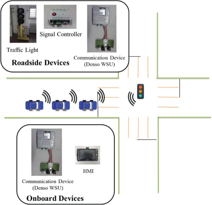
Driver assistance system prototype.
Field tests and results analysis
The field tests were conducted on a flat concrete road with no ramps. In the tests, the vehicles waited in a queue with a bumper–bumper interval of 2 m after the stop line. When the traffic light switches are about to turn green, the HMI prompts the drivers to start up their vehicles. In addition, we also conducted a control experiment, in which the test vehicles started up normally from a traffic light, to reflect the normal delay when vehicles start up one at a time after observing the motion of the preceding vehicle.
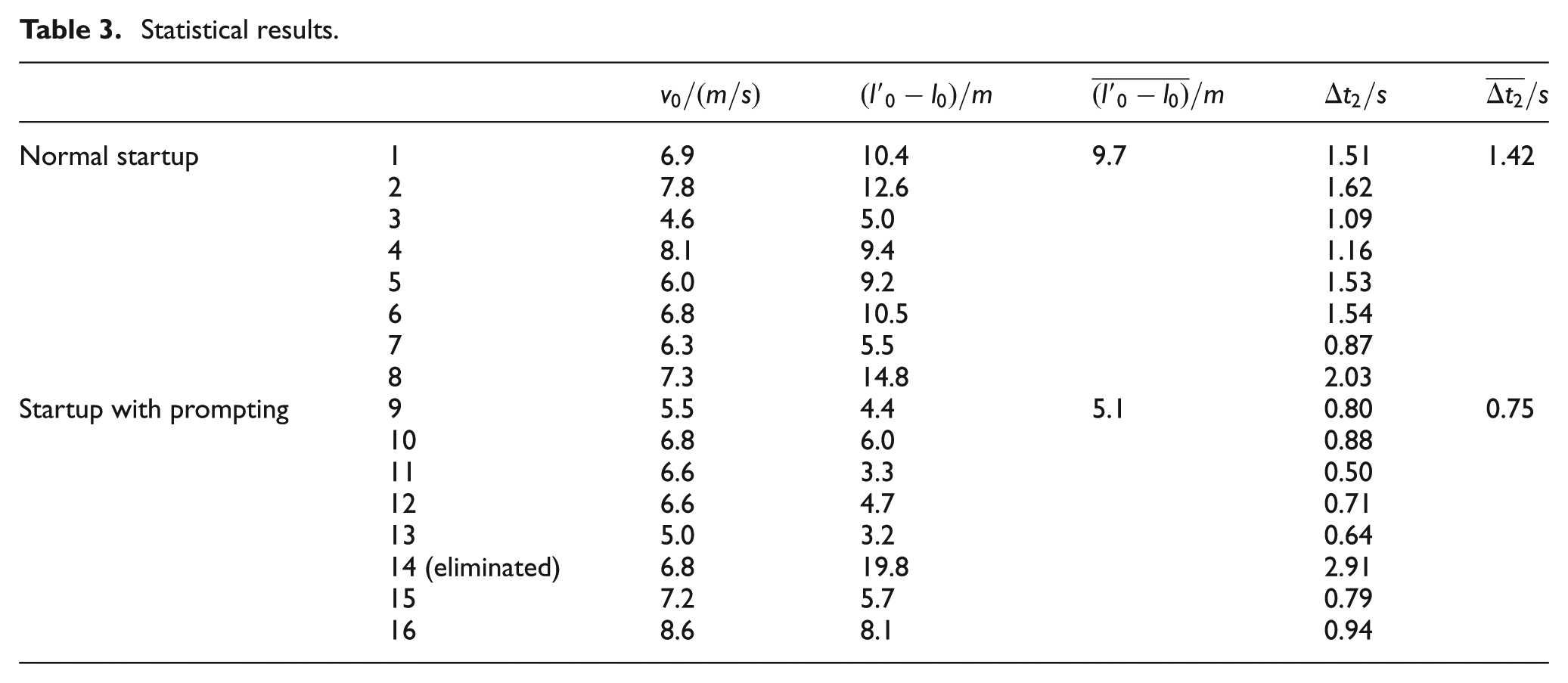
In the field tests, we recorded the velocities and following distances. Figures 11 and 12 show the velocity and following-distance curves, and Table 3 shows the statistical results.

Velocity and following-distance curves (normal startup).

Velocity and following-distance curves (startup with prompting).
Statistical results.
From the velocity curves, we see that the startup delay of two adjacent vehicles is reduced when drivers are prompted to start up their vehicles. As shown in Figure 12, the velocity curves increase at the same time and are twisted together when drivers are prompted to start up their vehicles, whereas in Figure 11, the curves begin to increase at different times, have an obvious time interval difference, and the curves are separate.
From the following-distance curves, we see that the following distance is greatly reduced from more than 10 m to less than 5.5 m when using the driver assistance system, which helps to save space in the intersection during the startup process, thus improving the capacity of the intersection.
From Table 3, we see that the difference between the two vehicles’ displacement during the startup process can be reduced from 9.7 to 5.1 m, and that the startup delay of two adjacent vehicles can be reduced by 47.2% (from 1.42 to 0.75 s) on an average if drivers are assisted by the system. In addition, the experimental results indicate that the value of Δt 2 was estimated accurately.
Conclusion and discussion
In this article, we propose a driver assistance system based on V2I communication technology. This system helps drivers start up their vehicles from traffic lights and decrease startup delays.
First, we define the function of the system and describe its architecture. And we propose a vehicle startup model that reflects the normal startup process and use this model to estimate the startup delay between two adjacent vehicles (1.48 s) using traffic monitoring data.
Then, we propose a driver assistance algorithm that contains two types of driver assistance methods: startup prompting and automatic startup control. The proposed automatic startup control method, based on fuzzy logic control, is compared in the simulation tests with an LQ-based controller. The simulation test results show that the fuzzy controller yields a faster response to the reference velocity and a smaller startup delay (a total of 10.09 s for five vehicles to pass the stop bar).
Finally, a prototype system is constructed to provide startup prompting and is tested in field experiments. The results show that the startup delay between two adjacent vehicles is reduced by 47.2% (from 1.42 to 0.75 s) on an average.
In future studies, we will consider driver acceptance and behavioral characteristics. Automatic startup control will also be added to the prototype system to improve its practicality.
Footnotes
Acknowledgements
The authors especially thank Fang Zhang, Xiaohui Qin, Di Wang, and Xiang Gao for their help and assistance.
Academic Editor: Seung-Bok Choi
Declaration of conflicting interests
The author(s) declared no potential conflicts of interest with respect to the research, authorship, and/or publication of this article.
Funding
The author(s) disclosed receipt of the following financial support for the research, authorship, and/or publication of this article: The research was supported by the Chinese National Programs for High Technology Research and Development, no. 2014AA110302.