
Abstract
The motion characteristics and flow field variation of Thomson-type actuator have been investigated in this article, in which a two-dimensional axisymmetric cylindrical coordinate model is constructed and described by a set of multi-physical equations reflecting the flow field, transient electromagnetic field, electric circuit, and mechanical motion. The motion performance of the actuator and the pressure drag caused by the high-speed movement of metal plate are analyzed under different opening speeds. It shows that the pressure drag has a strong buffer effect on the actuator. The influence of the laminar and standard
Introduction
High-speed switch (HSS) based on Thomson-type actuator has gained more and more interests in the limit and fast breaking of DC fault current owing to its short delay time and high-response speed. Particularly, with the concept of hybrid circuit breaker proposed recently, combining HSS and power electronic device to commutate the fault current has become a critical issue in the DC breaking field.1–3 Since Thomson-type high-speed actuator has an important influence on the performance of HSS, it is of great significance to study the motion characteristics of the actuator, which can not only improve the construction of HSS but also enhance the reliability of the power system.
The work principle of Thomson-type actuator is presented in Figure 1. When a pulse current iC is injected into Thomson coil (TC), the eddy current iP in the metal plate is induced by the transient magnetic field. Then, a huge electromagnetic repulsion force is created to accelerate the moving of metal plate.

The work principle of Thomson-type actuator.
Traditional model of Thomson-type high-speed actuator is developed in coupling the electromagnetic and circuit equations, which has been introduced by Roodenburg et al., 4 Wu et al., 5 and Holaus and Fröhlich. 6 However, in these models, the variation of flow field in the actuator caused by the high-speed movement of metal plate is not considered, which may attribute to the following two aspects. On one hand, TC and metal plate of the actuator are installed in the open environment and the pressure variation around the metal plate is immediately balanced by the surrounding gas flow. Thus, the effect of flow field on the motion characteristic of the actuator can be neglected. On the other hand, the coupled solving without the consideration of flow field can reduce the computational cost greatly. Yet, for the construction of HSS filled with high pressure SF6 as shown in Figure 2, TC and metal plate are both sealed in a small chamber to prevent the erosion from ablated products after the breaking. In this case, the fast separation of TC and metal plate will lead to that the pressure in the actuator changes sharply. As a result, the pressure gradient across the metal plate increases rapidly and causes evident pressure drag. Besides, the pressure drag grows significantly as the speed and displacement of metal plate increase, which then has a strong buffer effect on the actuator. Generally speaking, the buffer design of HSS is more problematic than that of conventional breakers due to short open distance and large mass of the motion part. Thus, this buffer effect caused by pressure drag will not only simplify the buffer design of HSS but also reduce the mass of the motion part drastically.
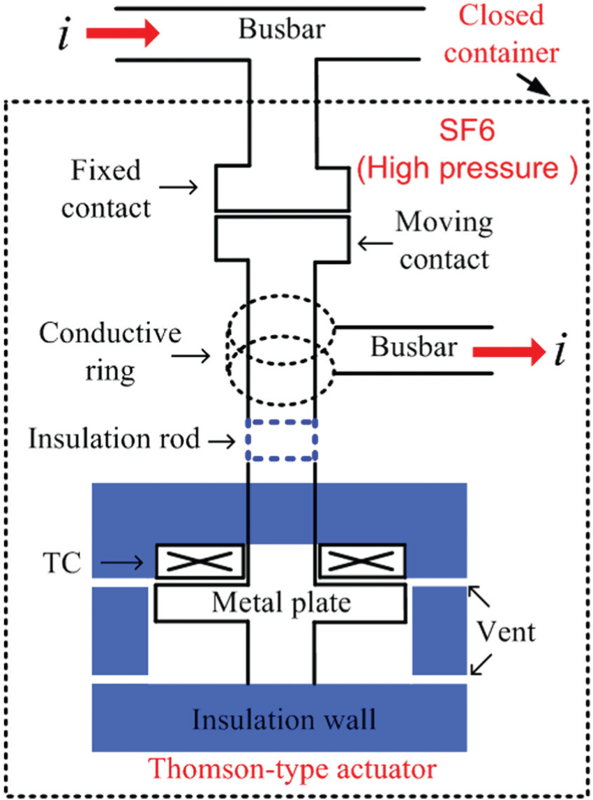
The construction of HSS filled with high pressure SF6.
In this article, a new model for Thomson-type actuator with electromagnetic field, circuit, mechanical motion, and flow field equations in coupling is developed. The motion characteristic of the actuator and pressure drag caused by the flow field variation are investigated for different opening speeds. Comparing the pressure and velocity distributions based on laminar and standard
Numerical model
The calculated model
Figure 3 presents the calculated model of Thomson-type actuator provided in Figure 2. In order to reduce the computational cost, a two-dimensional (2D) axisymmetric cylindrical coordinate model is adopted. The key parameters including coil circles, materials of coil and metal plate, as well as the initial distance between metal plate and coil are determined from our previous work. 5 The vents of actuator, which are used to balance the pressure variation caused by the high-speed motion of metal plate, are arranged uniformly at close and open positions. It is assumed that there are n vents, respectively, at close and open positions. Then, the vent width d for 2D model equivalent to that of three-dimensional (3D) model is given by the following relation
where R is the radius of metal plate, A the cross area for each vent, and

The calculated model of Thomson-type actuator provided in Figure 2.
Governing equations
The simulation model is described numerically by a set of multi-physical equations including hydrodynamic, transient electromagnetic field, electric circuit, as well as mechanical motion equations.
Hydrodynamics equations
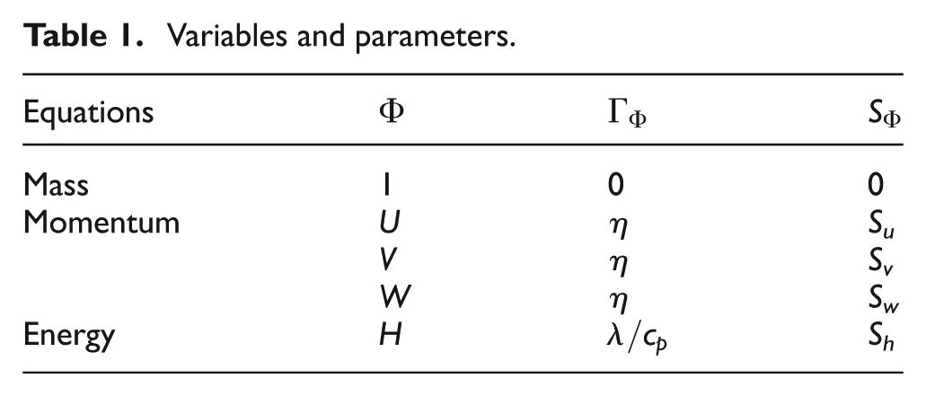
The conservation laws of the compressible gas are described by the continuity equation, Navier–Stokes equations, and energy equation, respectively,7–10 which can be written in the generic partial differential equations as follows

where
Variables and parameters.
In addition, the dynamic grid technique is applied to deal with the deforming fluid region and update the cells.
Transient electromagnetic field equations


where
Circuit equations
Figure 4 shows the external discharged circuit of Thomson-type actuator. VT is thyristor and VD is diode to conduct the exponential decaying current of TC. C is the pre-charged capacitor. The current in C, VD, and TC are marked as i 1, i 2, and i, respectively. R 1, R 2, L 1, and L 2 are the resistance and inductance of the linking wire. R and L are the equivalent resistance and inductance of TC, which are calculated from ANSYS in each time step. The on-state voltage drops of VT and VD are both defined as UT . When VT is turned on, the pulse current discharged by C is injected into TC. As the direction of the eddy current generated in the metal plate is opposite to the pulse current, huge electromagnetic repulsion force forms between TC and metal plate, which drives the metal plate to separate from TC with extremely high acceleration. Before the pulse current rises up to the maximum level, the voltage across VD (uVD ) is negative and the diode does not conduct. During this period, the voltage across C (uC ) and the branch currents are obtained by solving the following equations


The external discharged circuit of Thomson-type actuator.
With the energy stored in C released continually, i 1 starts to drop and uVD begins to increase. When uVD > UT , VD turns on. i, i 1, and i 2 are given by


When uC < uVD , the discharging of C is cut off and i equals i 2, which is determined by equation (11). The whole discharge process is completed after the energy stored in TC is released through VD.
Motion equations
When the external circuit of the actuator is discharged, the drive force of metal plate depends on the electromagnetic force (FZ ) between metal plate and TC and the pressure drag (Fd ), wherein FZ is solved according to the virtual operation principle described by (14). The motion equations of the actuator are described by equations (14)–(17)


where m is the mass of the motion part of HSS, w is the virtual work. v, a, and s are the speed, acceleration, and displacement of metal plate, respectively.
The coupled solving process for each time step is provided in Figure 5. The flow field calculation is based on FLUENT platform, in which the real gas model is adopted. The current and voltage of TC as well as the electromagnetic force are all calculated by ANSYS first and then coupled to the motion equations to obtain the speed of metal plate. Afterwards, this speed is read out by FLUENT and used as the speed of the dynamic grid. Meanwhile, with the flow field calculated by means of hydrodynamics equations, the pressure distribution is obtained and the pressure drags on both sides of metal plate are determined, which is then added to the electromagnetic force calculated in the next step to solve the motion equations.

The coupled solving process for each time step.
The influence of the pressure drag on the motion characteristic
In this section, the motion characteristic under different opening speeds are studied in order to determine the influence of pressure drag on the movement of metal plate. The parameters used in the numerical model are given in Table 2. The energy stored in the capacitor is changed by adjusting the capacitance, which can achieve different opening speeds of metal plate. The laminar model is taken in the calculation of the flow field and the time step is set to 5 µs
The parameters used in the model.

Figure 6 shows the calculated results of FZ , Fd , speed, and displacement of metal plate for different capacitances during the opening. As can be seen, as FZ grows, the metal plate separates from TC at about 0.25 ms. It leads to that Fd increases rapidly and becomes higher than FZ after 1.22 ms for C = 4.7 mF and 1.25 ms for C = 3 mF. Then, the speed of metal plate reaches its highest value with 12.3 and 8.7 m/s, respectively. After that, along with the buffer effect brought by Fd increasing, the speed tends to drop. When the metal plate approaches the end position, its speeds for these two capacitances reach 5.8 and 2.5 m/s with their respective decreases of 52.8% and 71.3% in comparison with the highest speeds. This indicates that Fd can be used as the buffer of the actuator. Besides, the flow field has little influence on the motion characteristic in the beginning 1 ms by comparing FZ and Fd . Consequently, the high-response speed of HSS will not be affected by the pressure drag.

The calculated results of electromagnetic force (FZ ), pressure drag(Fd ), speed, and displacement of the metal plate for different capacitances.
Comparison of different viscosity models in flow field calculation
In order to determine the influence of different viscosity models on the pressure drag, the laminar and standard
The standard

where
The turbulent viscosity

Figure 7 shows the pressure distributions on both sides of metal plate at t = 2 ms based on laminar and standard

The pressure distributions in the actuator at t = 2 ms: (a) laminar model and (b) standard
Figure 8 presents the gas velocity distributions in the actuator at t = 2 ms based on laminar and turbulence models. The flow velocity within the vent and gap for the turbulence model is about 20% higher than the laminar, which arises from that the pressure gradient across the metal plate for the turbulence model is much larger. Besides, affected by the jet flow from the vents and gap, several eddies form in the low-pressure side behind the metal plate in order to accelerate the balance of pressure.

The gas velocity distributions in the actuator at t = 2 ms: (a) laminar model and (b) standard
Figure 9 shows the waveforms of FZ
, Fd
, speed, and displacement of metal plate for laminar and standard
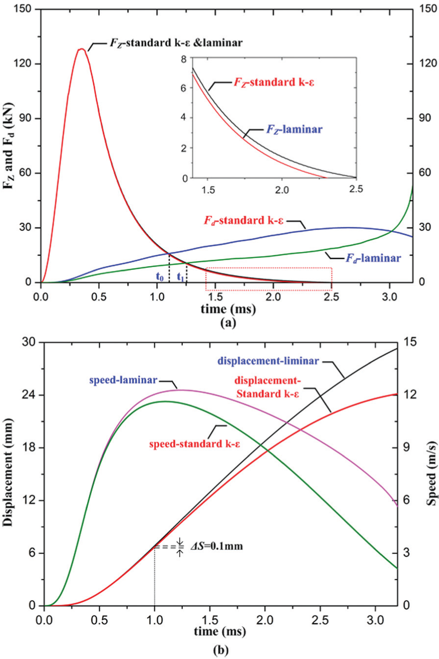
The waveforms of electromagnetic force (FZ
), pressure drag(Fd
) speed, and displacement of metal plate for laminar and standard
Discussion
As seen from the results in Figure 9, the speed at the end of stroke based on laminar model is still rather high. This may result in that serious stroke occurs on metal plate at the end of opening process. Thus, it is necessary to improve the damp effect of pressure buffer to reduce the speed of metal plate at the end of stroke. There are several factors affecting the pressure buffer during the opening process of HSS, such as the initial pressure P and the vent width d. Table 3 provides the calculated metal plate maximum speed, the displacement at 2 ms, as well as the speed at the end of stroke with d = 2 m for initial pressure P = 0.4, 0.5, and 0.6 MPa. Clearly, as P increases, the maximum speed of metal plate and displacement both reduce, which mainly arises from that the increase in P causes stronger pressure buffer. Compared with P = 0.4 MPa, the displacement, maximum speed, and speed at the end of stroke for P = 0.5 and 0.6 MPa decrease by, respectively, 3.3% and 5.9%, 5.7% and 9.8%, as well as 32.7% and 55.8%. These results indicate that the increase in P, on one hand, has little influence on the fast opening characteristics of HSS. On the other hand, its increase is very favorable to reduce the speed at the end of stroke.
The calculated results with d = 2 mm for different initial pressures.

Table 4 presents the calculated metal plate maximum speed, the displacement at 2 ms, as well as the speed at the end of stroke with P = 0.4 MPa for different vent width d. As can be seen, as d decreases, the moving speed and displacement of metal plate both tend to decrease, which results from that the gas flow channel to balance the pressure distribution becomes smaller and thus causes a stronger pressure buffer. Fortunately, the decrease in d has small effect on the displacement and maximum speed of metal plate. In contrast to d = 2 mm, the displacement, maximum speed, and speed at the end of stroke for d = 1.5 and 1 mm decrease by, respectively, 2.6% and 4.3%, 4.1% and 6.6%, as well as 27% and 48.1%. These suggest that the decrease in d is beneficial for the deceleration at the end of stroke. Meanwhile, it will not affect the fast opening characteristics of HSS.
The calculated result with P = 0.4 MPa for different vent width d.

Conclusion
A new model for Thomson-type actuator is built in this article with coupled interactions among the flow field, transient electromagnetic field, electric circuit, and mechanical motion taken into account. Especially the flow field variation during the high-speed opening is focused on. The pressure drags on both sides of metal plate are studied for different opening speeds. The pressure distributions based on the laminar and standard
The metal plate plays a crucial role during the fast opening of HSS. It can be used as not only the drive plate but also the buffer plate, which will simplify the buffer design of mechanism greatly.
During the initial 1 ms, the pressure drag is much lower in comparison with the electromagnetic force and thus will not affect the high-response speed of HSS.
The pressure drag based on the turbulence model is higher than the laminar model and has a stronger buffer effect on the actuator, especially after 1.5 ms since the opening operation. Besides, the increase in initial pressure and reduction in vent width are beneficial for the deceleration at the end of stroke and have little effect on the opening characteristics of HSS.
Footnotes
Academic Editor: Chin-Lung Chen
Declaration of conflicting interests
The author(s) declared no potential conflicts of interest with respect to the research, authorship, and/or publication of this article.
Funding
The author(s) disclosed receipt of the following financial support for the research, authorship, and/or publication of this article: This work was supported in part by National Key Basic Research Program of China (973 Program) (2015CB251001); The Science and Technology Project Funds of the Grid State Corporation SGSNK00KJJS1501564; the National Natural Science Foundation of China 51221005, 51377128, and 51323012; the Fundamental Research Funds for the Central Universities; the Program for New Century Excellent Talents in University; and Shaanxi Province Natural Science Foundation (2013JM-7010).