
Abstract
The currently used method to calculate radius of curvature of a cylindrical cam’s planar expansion pitch curve produces errors. Therefore, there is an urgent need to find an accurate method for cylindrical cam design. This research utilizes the three-dimensional expansion curve coordinates of the follower’s motion track and establishes the planar expansion pitch curve equation with the consideration of deviation angle, which can be easily used to analyze and design an oscillating follower cylindrical cam. The deduced equation of radius of curvature is based on motion law of the mechanism and prime cylinder radius of the cam. The relation curve between minimum radius of curvature and prime cylinder radius, which takes into consideration that planar expansion pitch curve varies with prime cylinder radius in the event of certain motion law, is described by MATLAB, and specific minimum radius of prime cylinder is generated for each allowable radius of curvature according to the relation curve. Thus, geometric parameters of a cylindrical cam can be designed. The feasibility of our methodology is validated with a specific example.
Introduction
Cylindrical cam mechanisms are common in machinery field. Compared with other mechanisms, cylindrical cam mechanisms have the advantages of small size, compact structure, good rigidity, high driving torque, and so on. The pitch curve of a cylindrical cam is a complex spatial curve, so that it is hard to design the pitch curve of it based on the motion law of the follower. In general, for the sake of simplifying design and manufacture process, a design of a cylindrical cam is to expand the surface of the cam and calculate the planar expansion pitch curve coordinates and also determine geometric parameters of the cam according to the engineering conditions such as allowable pressure angle and radius of curvature.
When designing an oscillating follower cylindrical cam mechanism, it is highly significant to calculate the minimum radius of curvature
Scholars all over the world have conducted a lot of researches on cylindrical cam and proposed many methods to calculate the planar expansion pitch curve coordinates as well as its radius of curvature. For example, Liu et al. 4 deduced the contact line equation of cutter surface revolution and workpiece spiral surface which have universal meaning, strong operability, and good use for reference value for the analysis of other cams. Hidalgo-Martínez 5 discussed the application of Bézier curves for designing cams and proposed a numerical method for optimizing the design of the cam profile using a Bézier ordinate as an optimization parameter. This kind of cam–follower mechanisms is recommended in applications where the space is restricted and very high forces are involved. Hung and Lai 6 presented a system for the design and manufacturing of cylindrical cams to cut the roller groove using small-sized tools. Hsieh and Lin 7 deduced profile equations of spatial cam through matrix transformation, according to pure rolling condition of the roller on the pitch curve of cam. Hsieh 8 and Grant and Soni 9 described theoretical scheme for the process of cylindrical cam. Thinh and Joong 10 proposed a method of designing flexible cam profiles using smoothing spline curves. However, with the consideration of practical engineering application, it is still necessary to find a method which has the virtues of uncomplicated, high precision and obvious geometric property. Shi and Wu 11 and Norton 12 discussed the techniques of plotting the planar expansion pitch curve, obtaining its coordinate equations, and deducing the radius of curvature. However, these methods generated errors when dealing with the offset between the trace point and the rotating axis of cam because they incorrectly assumed that the moving locus of the trace point on the expansion surface is an arc. Three-dimensional (3D) expansion method is an error-free method to expand the pitch curve of a cylindrical cam, which was proposed by Yong, 13 Chen and Wu, 14 and so on. However, they have not performed further research on the radius of curvature.
The aim of this research is to establish the planar expansion pitch curve equation with the consideration of deviation angle by analyzing the 3D expansion curve coordinates of the follower’s motion track and thus to propose an accurate design method for cylindrical cam with oscillating follower.
Existed errors in commonly used methods
A cylindrical cam mechanism is composed of a cylindrical cam and a follower which is driven by the rotary motion of the cam. Followers can be divided into two categories, namely, translating follower and oscillating follower. Cylindrical cam mechanisms with translating follower are always designed with graphic methods, which have been studied well these years and will not be discussed here. We will mainly analyze the design errors of cylindrical cams with oscillating follower caused by “Δ,” as shown in Figure 1.
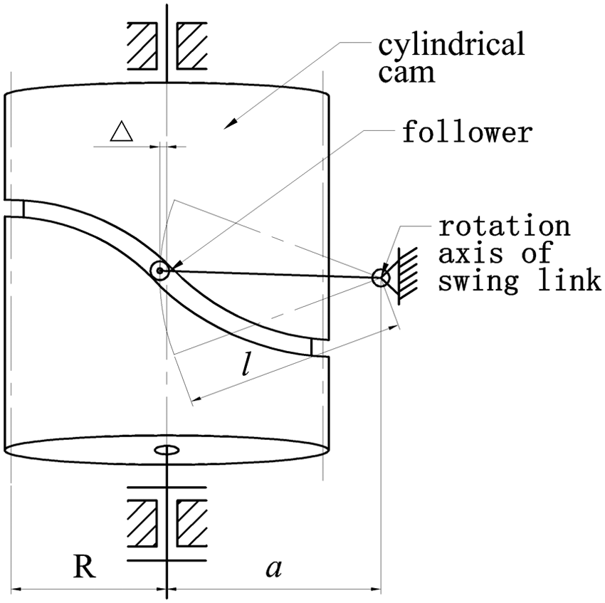
Cylindrical cam with oscillating follower.
The frequently used method to analyze an oscillating follower cylindrical cam is called plane expansion method. To do this, one should first expand the cylindrical surface of the cam to a rectangular plane and then calculate the pressure angle, radius of curvature, and so on of the planar expansion pitch curve. This method is feasible when the axis of the follower and the axis of the cam intersect or, in other words, when the axis of the follower is perpendicular to the surface of the cam. As for oscillating follower cylindrical cam mechanism, when we consider the arc motion of the follower, there is an offset between the follower and the axis of cylindrical cam, so that the axis of the follower is not perpendicular to the surface of the cam. In this case, the plane expansion method would produce errors. 15
Shi and Norton discussed the expansion of cylindrical cam pitch curve in accordance with its prime cylinder; details are shown in Figure 2.
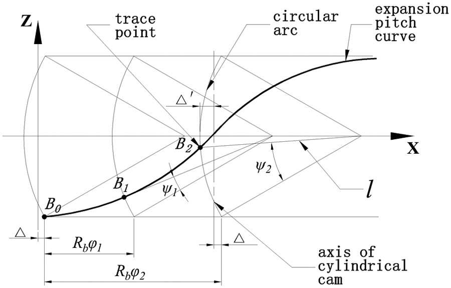
Expansion pitch curve in accordance with prime cylinder.
The moving locus of the trace point is arc, which is projected on the surface of prime cylinder, as shown in Figure 3. Thus, we can see that the locus, which is expanded in accordance with prime cylinder shown in Figure 2, is definitely not an arc. The distance between the trace point and the axis of cylindrical cam is

Diagram of the corresponding arc.
Design oscillating follower cylindrical cam’s planar expansion pitch curve and determine its radius of curvature
Here, we will assess the working processes and working conditions of cylindrical cam mechanisms. According to the motion law of relationship between the rotation angle of the cam
The 3D expansion curve of follower’s motion track
The follower moves through the groove, driven by the rotary motion of the cylindrical cam. The circular motion of the follower in the rotation plane can be divided into two orthogonal linear motions. So, the overall motion of a cylindrical cam mechanism is composed of the rotation of the cam and two linear motions of the follower, which is a spatial motion. 17 Moreover, the spatial motion of cylindrical cam with oscillating follower can be transformed into a surface motion. The surface is a cylinder whose radius is equal to the length of swing link, called 3D expansion surface, 18 as shown in Figure 4. According to the motion law, the relationship between the swing angle of the swing link and the rotation angle of cylindrical cam can be defined as equation (1)

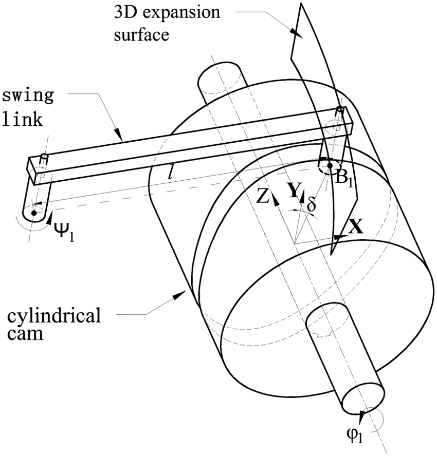
The 3D expansion surface of cylindrical cam.
According to equation (1), corresponding points can be found on the 3D expansion surface if it is picked up by random points on the pitch curve, which is the path of the trace point, to form the expansion pitch curve. The system equations of expansion pitch curve in Cartesian coordinates are shown in equation (2)

Equation of the planar expansion pitch curve
In the motion of an oscillating follower cylindrical cam mechanism because of the offset between the trace point and the axis of cylindrical cam, the center line (Y-axis) and the line connected by the trace point with the center of the prime cylinder on the surface of prime cylinder form an angle, which is called deviation angle


According to proportional transformation of the circumference length, equation (4) is transformed into equation (5) to make the units identical

Expression of the radius of curvature
We assume that parametric equation

is second differentiable, then

Thus, we can deduce the expression of the radius of curvature as follows

As for the expression of the planar expansion pitch curve, according to equation (5)


It is known that a convex portion of the cam pitch curve has a positive

Relation curve between the minimum radius of curvature and the prime cylinder radius
In equation (9),
An example for design using this newly developed method
Let us consider an example to compare the new method proposed above with the former method. In this example, we will calculate the equations of coordinates of planar expansion pitch curve with the two different methods in same conditions and give the contrast analysis of the minimum prime cylinder radius.
We assume that the equation of the follower’s motion law

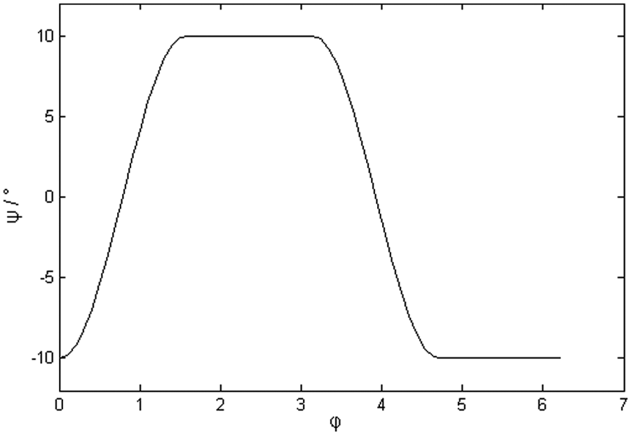
Motion curve.
Thus, the relation curve between the minimum radius of curvature and the prime cylinder radius according to this motion law can be described by MATLAB. We can also obtain the value of minimum prime cylinder radius when allowable radius of curvature is 20 mm. The known conditions are
The relation curve between the minimum radius of curvature and the prime cylinder radius is shown in Figure 6, and the minimum prime cylinder radius is 59.4 mm when the allowable radius of curvature is 20 mm.

Relation curve between the minimum radius of curvature and R (3D expansion).
According to equations (5) and (10), the system equations of planar expansion pitch curve are obtained, where R = 59.4 mm is the prime cylinder radius, l = 253 mm is the length of the swing link, and a = 251 mm is the displacement between the rotation axis of swing link and the axis of cylindrical cam

The planar expansion pitch curve is shown in Figure 7.

Planar expansion pitch curve.
By modifying allowable radius of curvature into some specific values in the programs, the corresponding minimum radii of prime cylinder are shown in Table 1.
Relation table between allowable radius of curvature and minimum R (3D expansion).

If expanded according to Shi and Wu 11 and Norton, 12 the obtained system equations of coordinates of planar expansion pitch curve are

According to equation (12), by deriving expression of the radius of curvature and writing MATLAB programs, the relation curve between the minimum radius of curvature and the prime cylinder radius can be plotted as Figure 8, and the minimum prime cylinder radius is 60.2 mm when the allowable radius of curvature is 20 mm.

Relation curve between the minimum radius of curvature and R (plane expansion).
By modifying allowable radius of curvature into some specific values in the program, the corresponding minimum radii of prime cylinder are shown in Table 2.
Relation table between allowable radius of curvature and minimum R (plane expansion).

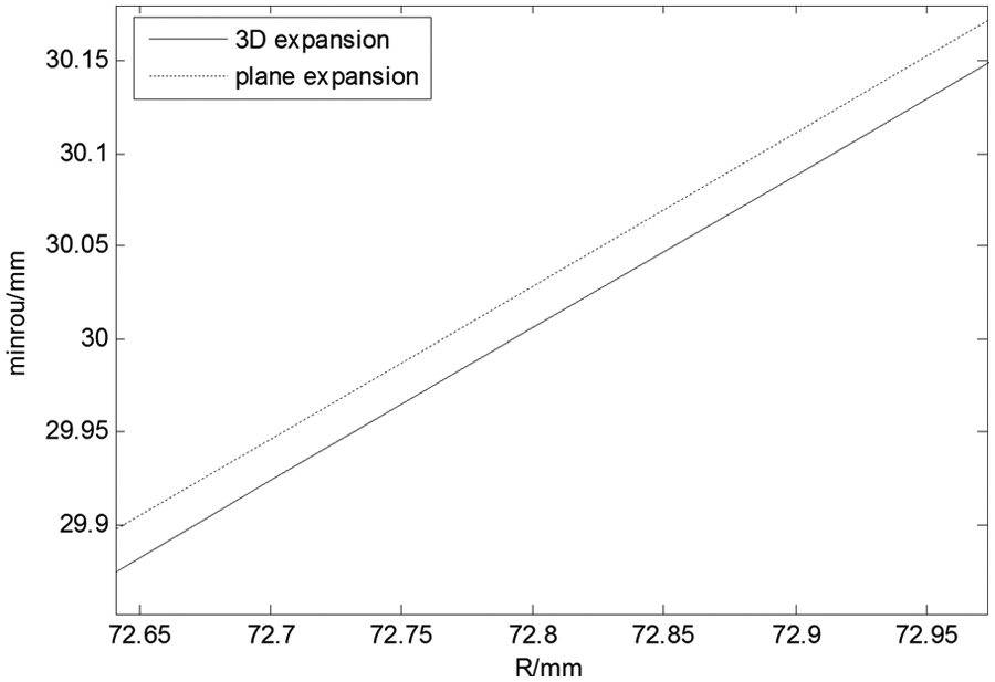
The contrast of relation curves between the minimum radius of curvature and the prime cylinder radius based on these two methods is shown in Figure 9.

Contrast of relation curves between the minimum radius of curvature and R.
We can see from Tables 1 and 2 and Figure 9 that the difference gradually increases between minimum radii of prime cylinder based on these two methods when allowable radius of curvature increases. When allowable radius of curvature reaches above 30 mm, the difference is 0.8 mm or more, so that the difference between the result obtained according to Hsieh 8 and Grant and Soni 9 and that obtained according to 3D expansion method is obvious.
Besides, it is worth mentioning that considering the error existed in plane expansion, a method is described in Grant and Soni
9
to correct the pitch cylinder radius

The derived system equations of coordinates of planar expansion pitch curve are

The relation curve between the minimum radius of curvature and
Contrast of relation curves between the minimum radius of curvature and R.
We can see from Figure 10 that when allowable radius of curvature is 30 mm, the difference between minimum radii of prime cylinder based on these two methods is less than 0.1 mm. Nevertheless, errors still cannot be eliminated through this correction. Because it reduces errors by broadening the motion distance of the rotation axis of swing link on the expansion surface, instead of polishing the difference in length between arc
Above all, in view of the virtues of uncomplicated and error free, the expression of radius of curvature of cylindrical cam’s planar expansion pitch curve, as well as relation curve between the minimum radius of curvature and
Conclusion
By analyzing the working process of cylindrical cam mechanisms, we have discussed the errors in the existing methods for the planar expansion pitch curve of cylindrical cam with oscillating follower and the calculation of its radius of curvature.
According to motion law of cylindrical cam mechanism, we have deduced error-free equations for surface expansion pitch curve and methods for calculating radius of curvature by applying 3D expansion formula of the follower’s motion track.
The relation curve between the minimum radius of curvature and the prime cylinder radius can be drawn by MATLAB, and the minimum prime cylinder radius can be determined when radius of curvature is greater than allowable value. The feasibility of our theory is validated by a specific example with comparison.
Footnotes
Appendix 1
Academic Editor: ZW Zhong
Declaration of conflicting interests
The authors declared no potential conflicts of interest with respect to the research, authorship, and/or publication of this article.
Funding
This study was sponsored by Natural Science Foundation of Zhejiang Province (no. LY12E050081).