
Abstract
To conduct an in-depth analysis of the wheel rim forming processes and effectively control rim forming quality defects, three-dimensional elastic–plastic finite element models of flaring and three rolling processes for 22.5 × 9.0-type steel wheel rim were established using ABAQUS software. Some key techniques in establishing models were investigated, such as methods of imposing boundary condition given by side guide wheels and enforcing load curve. The accuracy of the models was verified by comparing the simulation results with the point-cloud model of the actual produced rim in terms of exterior shape and thickness. Distributions and changes in the equivalent stress and equivalent plastic strain were analysed. The results indicate that the rim misalignment defect often occurs when the unequal width of the reserved material at the two ends of the rim is in the first rolling process. An improved die design is proposed. The results of the finite element analysis indicate that the improved dies are conducive to the flow of the material between the gap of the upper roller and the lower roller, and the difference in the rim width is significantly reduced.
Introduction
The advantages of tubeless steel wheels are highly recognised by the global steel wheel industry. Tubeless steel wheels are suitable for highway driving as they exhibit distinct safety and fuel economy characters. As shown in Figure 1, the wheel is formed by the rim and the spoke, which are welded together. As the rim directly mounts the tyre and bears the most force from automobile body, 1,2 the forming quality of the rim directly impacts the performance of the wheels.

Tubeless steel wheels.
The rim is a rotating object. Figure 2 displays the structure diagram of the rim, which usually includes the flange, the bead seat, the rim well and the welding surface with spoke. To install the tyre conveniently, the cross-sectional shape of the rim is asymmetric, the well is closer to one end and the flanges of both ends are identical. The main forming processes for the rim as shown in Figure 3 are as follows: blanking → edge rolling → butt welding → welding slag cleaning → flaring → first rolling → second rolling → third rolling → expansion and finishing → punching valve hole. Flaring and three rollings 3,4 are the focal steps of the forming processes.

Structure diagram of a rim.
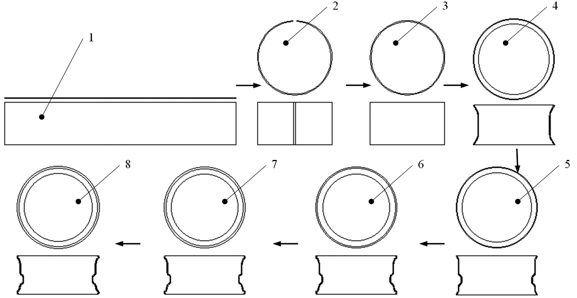
Main forming processes for the wheel rim.
The study on the rim forming processes primarily employs a trial-and-error method in real production. Qualified rim products are obtained by adjusting process parameters and improving dies design with multiple trials and engineers’ technical experience. The finite element method (FEM) numerical simulation technique plays a significant role in predicting product forming defects and reducing the production cost and product development cycle. Thus, the study on the rim forming processes using FEM has practical significance.
Due to the characteristics of an intricate cross section and a large number of forming steps and process parameters, there are limited literatures that discussed wheel rolling process especially rolling process for tubeless steel wheel rim of automobile. Shen et al. 5,6 proposed some strategies on railway wheel rolling simulation using software SuperForm. In modelling, a virtual mandrel is exploited in the hub hole to keep the wheel central instead of the guide rolls and centring rolls. The detailed information about metal flow in railway wheel forming process was deeply investigated. Although omitting the centring rolls and guide rolls can simplify the model, the boundary conditions were not inconformity with the real case. Ward and colleagues 7,8 described the finite element simulation of the multi-stage railway wheel and tyre forming process using the DEFORM™ two-dimensional (2D) metal forming programme. But the ring rolling process was included by assuming pseudo-plane strain metal flow, which was different from the production.
Researchers achieved remarkable progresses on the application of the finite element simulation to the railway wheel rolling process. However, the workpiece of railway wheel in rolling process is a bulk specimen. And during the forming process, the portion of the workpiece undergoing plastic deformation is much larger than the portion undergoing elastic deformation, so the elastic deformation can be generally neglected. By contrast, the workpiece used for deforming tubeless steel wheel rim of automobile is a sheet specimen, and the elastic deformation cannot be neglected. Thus, the metal forming mechanism during the rim rolling process is far different from that in the railway wheel rolling process, the mechanism remains ambiguous and eliminating forming quality defects remains unresolved.
The radial–axial ring rolling process and the tubeless steel wheel rim rolling process exhibit lots of similarities. So, related methods and results for radial–axial ring rolling forming process are referenced to study rim rolling process. Many researchers have achieved some accomplishments in the finite element simulation analysis of the ring rolling process. Nefussi et al. 9 analysed the cold rolling process of a ring piece using the rigid-plastic FEM. Utsunomiya et al. 10 researched the problem of ring swing and the distribution of thickness through simulating cold ring rolling process, and the research was based on the elastic–plastic FEM. The ring has a rectangular cross section, and the entire ring was analysed under the plane-strain condition. Song et al. 11 used software Marc to study the hot rolling process of IN718 material, and a thermal–mechanical coupling FEM simulation model was set up, and the accuracy of the model was verified. Anjami and Basti 12 established a thermal–mechanical coupled FEM model for hot rolling of large rings and investigated the size effects of rolls on forming quality. The achievements can clarify the plastic deformation and heat transferring of hot rolling of large rectangular section rings. Zhou et al. 13 –15 explored the effects of the axial roll motion and size on the radial–axial ring rolling process, optimised parameters within a reasonable range and developed useful suggestions regarding the axial roll motions and roll sizes in the actual production process. Guo and Yang 16 established a finite element model for the radial–axial ring rolling forming process and analysed the relationships among process parameters. They developed the foundation for obtaining the plastic deformation mechanism of the materials and achieving stability in the production process.
The above-mentioned achievements and results reveal the forming mechanism and rules of ring rolling effectively. Those are important references for the simulation study of the rim rolling process. However, all these researches have focused on simple profile ring rolling such as rectangular cross section. Also, these rings have been bulk specimens, and the springback analysis of the workpiece has not been involved. Tubeless steel wheel rim of automobile has complex and asymmetric cross-sectional shape. In addition, the blank to form the rim is high-strength steel sheet, and springback is caused by the redistribution of stress in sheet material after the tools being removed. Because of the complexity of the process, the large number of process parameters, the interactions among the process parameters and the large scale of the numerical simulation calculation, so far, study on the metal deformation mechanism in rim forming process and the generation and control of defects remains deficient. Therefore, an in-depth analysis of the rim rolling forming mechanism and predictions of product forming quality defects by FEM and corresponding dies design improvements are important for improving the forming quality of the wheel rim.
Based on ABAQUS software, the main forming processes such as flaring and three rollings for the steel wheel rim with 22.5 × 9.0-type were numerically simulated in this article. The forming and springback processes during these steps were analysed. Some three-dimensional (3D) elastic–plastic finite element models for these process steps were established. Many corresponding issues during the modelling such as enforcing related boundary conditions and applying load curve of tools were solved. The correctness of the constructed models were verified by comparing the simulation results with the point-cloud model of the actual produced wheel rim in terms of exterior shape and section thickness. The distributions and changes in the equivalent stress and equivalent plastic strain during the forming processes were analysed. To solve the flange misalignment defect, the design of rollers in the first rolling process was improved. The numerical simulation results indicate that the flange misalignment defect is reduced significantly with the improved rollers. These researches in this article provide important theoretical information for studying the material deformation mechanism during rim rolling process, optimising process parameters and improving rim rolling forming quality in future research work.
Principle of rim rolling process
Rolling is the central step in rim forming processes. An illustration of the rolling mill is shown in Figure 4, as seen in this figure, the rolling mill consists of the upper roller, the lower roller, the guiding wheels, the cylinder and the blank.

Illustration of the rim rolling forming device.
As seen in Figure 4, during the rolling process, the workpiece is first set through the lower roller, and subsequently, the lower roller which jacks up workpiece rises rapidly. When the distance is 30–40 mm from the workpiece to the upper roller, the upper roller and the lower roller begin to roll back. Simultaneously, the cylinder pushes guiding wheels downwards, and guiding wheels press onto the workpiece to ensure the stability of the workpiece as it rotates with the lower roller. As the lower roller continues to rise, the workpiece gradually approaches the upper roller. When the gap between the workpiece and the upper roller decreases to the minimum distance, the lower roller reduces the rising speed and continues to rise until the upper roller contacts the workpiece. The required shape of the workpiece is formed by the changes in the gap between the upper and lower rollers. When the lower roller rises to the highest position, it stops rising and enters into the prolonged rolling stage, which ensures a multi-circulation rolling process for forming. After a prolonged amount of time, the lower roller goes down rapidly while the cylinder pulls guiding wheels upwards. Upper and lower rollers gradually stop rolling, and the workpiece is taken out from the lower roller. The whole rolling process is completed.
Construction of the finite element model
Blank material
The main objective of this article is to analyse the rolling processes of the rim, discuss the causes of the flange misalignment defect and propose corresponding dies design improvement methods. Although microstructure and mechanical properties of the welding joint (including welding seam, welding heat affected zone and base metal) are different after the flash butt welding, the influence on this defect by the different properties of the welding joint can be ignored because the flange misalignment defect occurs at the axis direction of the rim. In order to simplify the finite element simulation model, material inhomogeneity for welding joint and effect on forming quality by welding joint are not involved in this article.
The material used for the rim is high-strength alloy steel with grade 380CL. The mechanical property data are obtained by the room-temperature tensile test on the blank with an electronic universal testing machine. The relevant material data are as follows: elasticity modulus E = 206.65 GPa, Poisson’s ratio v = 0.28 and thickness t = 6.75 mm. The true stress–plastic strain data for the material are shown in Figure 5.

True stress–plastic strain curve for the blank material.
Meshing blank
In order to increase the calculation efficiency, dies are assumed to be rigid bodies because of the small deformation during forming processes. Since the thickness t = 6.75 mm of the blank is relatively too thick, the adaptation of shell elements cannot reflect the change in thickness during rolling processes. Also, considering that both inside and outside surfaces of the deformed body contact with rollers in rolling processes, the C3D8R-type 3D eight-node reduced integration element is used, and the blank is meshed with 16,000 elements and 20,400 nodes. Figure 6 shows the model of the blank after meshing.
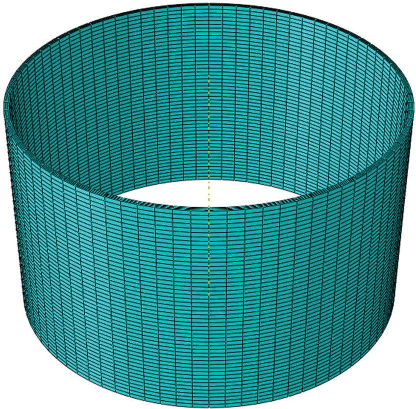
Model of the blank after meshing.
Boundary conditions
The side guiding wheels of the rolling machine tightly press on the workpiece by adjusting the cylinder air pressure, which prevents the axial direction swing of the workpiece during the rolling process. Thus, uniformity of rim rolling forming is achieved. To successfully simulate the flexible adjustment to the blank by guiding wheels in the actual production, a flexible connection in the form of a virtual spring is adapted to automatically adjust the contact between the guiding wheels and the workpiece. This method can provide a guiding system that exhibits a similar air pressure effect during the actual production process. In addition to the movement towards the centre of the blank and the rotation about its axis, other degrees of freedom of guiding wheels are restricted.
The movements of dies in the models follow their actual movements: the lower roller is an active roller and rises while rotating about its axis; the upper roller is a passive roller and rotates about its axis.
Load condition settings
In the flaring process step, the upper die moves downwards vertically and the lower die is motionless. To make the feeding motion of the upper die in the simulation be consistent with the actual production process, in which the speed of the upper die increases from zero to the maximum value and subsequently decreases to zero. A smoothing method provided by ABAQUS was employed to set the upper die feeding motion. The loading curve equation is as follows

In this equation, ξ = (t − t 0)/(t 1 − t 0), P = P 0 when t = t 0, and P = P 1 when t = t 1. The first and second derivatives at t 0 and t 1 are zero. This is a displacement–time curve. The analysis time step is 1.0 s, and t 0 = 0 and t 1 = 1. P is used to calculate the displacement of the upper die at different times and P 0 = 0 and P 1 = 1.
The analysis of the rolling process begins when the upper roller contacts with the workpiece. In the stable rim rolling process, the rising speed of the lower roller is nearly constant. Therefore, in the finite element model, the rising speed of the lower roller is assumed constant for every rolling process, and it is enforced in accordance with the actual production. Rising speeds are 5.3, 6.65 and 7.4 mm/s for the first, second and third rolling processes, respectively. And mass scaling factors were set at 10 to reduce simulation calculation time. The displacement of rising is 22 mm in the first rolling process, 18 mm in the second rolling process and 12 mm in the third rolling process. Every rolling process has two stages: the rising stage and the forming completion stage. The distance between the upper and lower rollers constantly decreases during the rising stage. In the forming completion stage, the distance between the upper and lower rollers does not change, but the rollers maintain rotation.
When the rolling process begins, the frictional force between the workpiece and the lower roller is not large enough to drive the workpiece rotating in the simulation. Therefore, to ensure that the workpiece rotates with the lower roller at the beginning stage, an initial rotational speed of 5 rad/s is assigned to the workpiece. The rotational speed of the rollers, the lower roller rising speed and the analysis time interval step in these three rolling processes are listed in Table 1.
Rotational speed of the rollers, rising speed of the lower roller and analysis time interval step.

Simulation analysis models of rim forming process
Figure 7 shows the FEM analysis models of flaring and the first, second and third rolling processes presented in this article.

FEM analysis models of rim forming process: (a) flaring, (b) first rolling, (c) second rolling and (d) third rolling.
Verification of simulation results
To verify the correctness of the simulation models, the workpiece obtained from the FEM simulation analysis (Figure 8(a)) is compared with the scanned point-cloud model of the actual production rim (Figure 8(b); CreaFrom handheld scanner, Model EXASCAN). Figure 8(c) shows the comparison of the exterior dimensions from the simulation results and the point-cloud model, after aligning and matching utilising Geomagic Qualify software. As shown in Figure 8(c), the exterior dimensions of the two models are similar. A small portion of the flange exhibits a relatively large difference of −3 to 3 mm, and the differences in other parts range from −2 to 2 mm; these findings prove the accuracy of the FEM models presented in this article.

Comparison diagram of the rim point-cloud model with the simulation results: (a) simulation results, (b) point-cloud model and (c) comparison result.
For further verification of the accuracy of the model in this article, the rim cross-sectional thickness from the simulation results is compared with the actual product. Figure 9 shows the measure point positions at the cross section of the actual product. Figure 10 displays the comparison diagram of the measured cross-sectional thickness and the simulation results at different points. As seen in Figure 10, simulated values are consistent with the actual measurement, and the maximum error between simulated values and actual measurements is about 6%. These results prove that the finite element models in this article are consistent with the actual production situation.

Measuring points at cross section of the rim.

Comparison of actual measured cross-sectional thickness with the simulated thickness at different points.
Analysis of simulation results
Figure 11 shows the distribution and change of the equivalent plastic strain in the workpiece during the rim forming process. As shown in Figure 11(a), the maximum equivalent strain appears at the bell mouth of the two ends of the workpiece after flaring, and the value is 0.099. This finding indicates that a relatively large plastic deformation of the blank occurred at the outer edge of the workpiece, which turned into a bell mouth. The equivalent plastic strain value steadily decreases from the two ends towards the centre and exhibits a minimum value of approximately zero at the centre part, which indicates the centre part has no deformation. According to Figure 11(b), the equivalent plastic strain value at the well is relatively large during the first rolling process. The maximum value of the equivalent plastic strain is 0.352, which appeared at the top and bottom round corners of the well and formed a strain ring at the round corner of the well. As shown in Figure 11(b), the equivalent plastic strain value on the A side of the well is greater than that on the B side. This result is due to the asymmetry of the rim cross section as the well is not located at the symmetric centre of the cross section but rather close to the A side. During the first rolling process, the metal on the A side is easier to flow into the well. As shown in Figure 11(c), the equivalent plastic strain is the largest at the round corner of the well and the flange during the second rolling process, which indicates that the plastic deformation of the material is relatively large at these locations to precisely form the well bottom and preform the flange. As shown in Figure 11(d), the equivalent plastic strain is relatively large at the flange during the third rolling process, and this process is primarily used for forming the flange precisely.

Distribution and change of the equivalent plastic strain in the workpiece during the forming process: (a) flaring, (b) first rolling, (c) second rolling and (d) third rolling.
Figure 12 is the contour diagram of equivalent stress of the workpiece after forming and unloading springback during the flaring and the three rolling processes. As shown in Figure 12(a), the edges of the workpiece produce relatively large equivalent stresses after flaring because the purpose of this process is to form the bell mouth at the two ends of the workpiece. The value of the maximum equivalent stress at the edge is 324.754 MPa, whereas the equivalent stress at the centre portion is much smaller about 30–50 MPa. The purpose of the first rolling process is to form the well. According to Figure 12(b), the equivalent stress of the workpiece is relatively large at the round corner of the well with a maximum equivalent stress of 574.296 MPa. During the second and third rolling process, as shown in Figure 12(c) and (d), the distribution and values of equivalent stress are similar, and both exhibit a relatively large equivalent stress at the flange with a maximum value of 597.638 MPa.

Contour diagram of the equivalent stress in the workpiece during the forming process: (a) flaring, (b) first rolling, (c) second rolling and (d) third rolling.
The equivalent stress of the workpiece reflects the maximum force exerted on dies. The equivalent stress contour diagram indicates that the round corners of the upper and lower rollers, which contact with the workpiece during the roll forming process, are relatively easy to wear. Hence, strengthening treatments for these parts of dies are needed. Tapered surfaces of guide wheels in contact with the workpiece flange will wear after long-term use. To ensure satisfactory forming quality of the workpiece, tapered surfaces should be refurbished or guide wheels should be changed when the guiding precision deteriorates.
Improvement of dies design and numerical simulation analysis
The three rolling processes comprise the main process in the rim forming. The forming quality defect of the workpiece in rolling processes is primarily caused by an unequal width of the flange at the two ends, which is referred to as misalignment. If the difference in the width of the flange at the two ends is large, the strength on one end of the rim will decrease due to a narrower flange and deformation will occur when the rim is used, and this can cause the gas leakage of tyres. The quality disfigurement of the misalignment is usually caused by the unequal reserved width at the two ends of the workpiece in the first rolling process. With the accumulation of the error in the subsequent processes, the difference in the flange widths at the two ends becomes larger than the allowed value. Figure 13 shows unequal reserved widths L 1 and L 2 after the first rolling process, which causes a misalignment defect. Thus, the misalignment defect can be effectively resolved when the difference in reserved width of the flange is as small as possible during the first rolling process.

Misalignment defect of the workpiece after the first rolling process.
As the well is located towards one end, the material on the two sides of the well has different plastic deformation during the first rolling process. In the original design of the rollers (Figure 14), the material is pressed at the two ends, which restricts the inward flow of the material and causes an unequal amount of material from the two ends to flow into the well bottom and an unequal reserved width of the flange on the two ends. To improve the flow of the material, the design of the rollers is improved. Figure 15 shows the improved rollers for the first rolling process.

Original design of the rollers in the first rolling process.

Diagram of the improved rollers in the first rolling process.
Figure 16 contains local diagrams of the finite element model for the first rolling process before and after the improvement of rollers design. As shown in Figure 16, the projecting will contact with the blank first to form the well of the workpiece, and the two ends of the improved upper roller do not press the workpiece, which is conducive for the material flow between the gap of the upper and lower rollers. Sufficient width is reserved at the two ends of the workpiece by the improved rollers, which is conducive for the equivalent width of the flange in subsequent processes and reduces the difference in flange width and controls the rim misalignment defect.

Local diagrams of the finite element models for the first rolling process before and after the design improvement of roller dies: (a) before dies improvement and (b) after dies improvement.
Figure 17 shows the cross section of the rim before and after the improvement of rollers design. According to Figure 17, the widths of the flange at the two ends before the improvement are 10.074 and 15.690 mm, respectively, which results in a difference of 5.616 mm. After the improvement, the widths are 11.862 and 12.389 mm, and the difference in the widths of the two ends flange is 0.527 mm. After the improvement of rollers design, the difference in the widths decreases significantly.

Cross sections of the rim before and after the improvement of the dies: (a) before dies improvement and (b) after dies improvement.
Conclusion
The following conclusions are drawn:
In this study, the finite element simulation models of the flaring, first, second and third rolling processes for the steel wheel rim forming were established. Also, a multi-step forming process numerical simulation analysis for 22.5 × 9.0-type steel wheel rim was performed. Some key techniques such as constructing the geometrical model, selecting elements, enforcing guiding wheel boundary condition and applying the load curve were resolved. The simulation results of the exterior shape and thickness distribution were verified, and the shape of the workpiece obtained by the simulation basically agrees well with the scanned point-cloud model of the actual product. The simulated thickness is primarily consistent with the actual measured values in the variation trend and values, and the maximum error is 6%, which proved the accuracy of the constructed models.
The results of the simulation indicate that the equivalent plastic strain and equivalent stress are relatively large at the bell mouth on the two edges of the workpiece in the flaring process. The degree of deformation of the material at the well is relatively large in the first rolling process, whereas plastic deformations of the materials on either side of the well are different. This causes an unequal amount of material on either side of the well entering the well and a relatively large amount of equivalent stress at the round corner of the well. The distribution of equivalent stress and equivalent plastic strain of the workpiece is similar during the second and third rolling processes, with a relatively large value at the round corner of the well and the flange.
Roller structure in the first rolling process was improved. The results of the finite element analysis indicated that the widths of the flanges at the two ends are almost the same, and the difference in the widths of the flanges significantly decreased from 5.616 to 0.527 mm after the design improvement. Thus, the improved rollers effectively control the misalignment defect of the rim.
Footnotes
Acknowledgements
Any underlying research materials related to my article can be accessed.
Academic Editor: Farzad Ebrahimi
Declaration of conflicting interests
The authors declared no potential conflicts of interest with respect to the research, authorship, and/or publication of this article.
Funding
This research work is financially supported by National Natural Science Foundation of China (approval no.: 51305144), Science and Technology Planning Project of Xiamen City under grant (approval no.: 3502Z20113020) and Promotion Programme for Young and Middle-aged Teacher in Science and Technology Research of Huaqiao University (approval no.: ZQN-PY203).