
Abstract
As one of largest optical units used in high-power laser inertial confinement fusion facility, the large-aperture transport mirror’s misalignment error can have a very negative impact on the targeting performance of laser beams. In this article, we have carried out a fundamental analysis on the mounting and misalignment errors of transport mirror. An integrated simulated assembly station is proposed to align the mirror precisely, and the design of transport mirror unit is optimized to satisfy the stringent specifications. Finally, methods that integrated theoretical modeling, numerical simulation, and field experiments are used to evaluate the mirror’s alignment, and the results indicate a more robust and precise alignment performance of new design.
Introduction
Thousands of optical units are used in the large high-power laser facility, SG-III at China Academy of Engineering Physics, a stadium-sized 48 beams laser constructed to create fusion conditions with controllable laboratory conditions. 1 Each laser beam in the inertial confinement fusion (ICF) facility consists of a multi-pass, regenerative amplifier followed by a power amplifier, a spatial filter to clean the beam, transport mirrors to convert laser path, and a final optics assembly, as shown in Figure 1. In each 3.75-kJ laser beam, hundreds of optical units are used as function-independent subsystems and we usually refer the optics as line-replaceable units (LRUs)—the packages for assembly, transportation, installation, and removal of optics. 2 LRUs represent the National Ignition Facility’s (NIF) design philosophy of modularity 3 —LRUs is design to assembly by standardized joints in laser building to form laser beams, so if one optic of the hundreds optical units suffer damage, the optic will be removed and replaced quickly, safely, and cost-effectively.
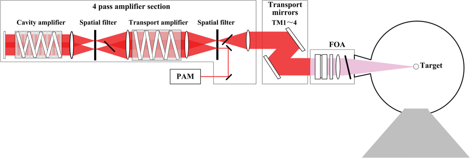
Schematic laser beamline in inertial confinement fusion (ICF) facility.
As the most powerful and largest laser in the world, ICF laser is designed/built so precisely that all laser beams can hit the target (∼250 μm focal spot) with the accuracy better than 30 μm (Root Mean Square, RMS) from numerous directions at the almost same time (within a few picoseconds). To realize these extreme specifications, thousands of LRUs must be manufactured and assembled with most stringent requirements. So, the optics assembly building (OAB), a 10,000-m2-sized Class 100 (ISO Class 5) cleanroom in SG-III facility, is built and all LRUs are assembled in that building with a condition of strict cleanliness and precise alignment. However, due to the fact that most technical requirements for large ICF optics are close to the limitations of state-of-the-art manufacturing/assembly/measurement technologies, there are huge challenges to assure the stringent specifications of large ICF optics assembly and mounting. In this article, the assembly and mounting performance of laser transport mirror LRU in switchyard, one of the largest ICF optics, is studied. Its assembly design, technical requirements are introduced at Section 2 and then, a fundamental analysis on the mounting and misalignment errors of transport mirror with the methods of theoretical modeling and numerical simulation, is carried out at Section 3. And the performance of mirror with new design improvements is also evaluated and testified by experimental studies.
Structure of large laser transport mirror and its alignment specifications
Before entering the target chamber, the laser beams travel through the switchyard where beams are redirected by transport mirrors to the upper and lower hemispheres of the target chamber, so they converge radially on the target (Figures 1 and 2). In a high-energy ICF laser environment with various physical phenomena (e.g. mechanical vibrations and laser thermal shock), the mirrors are specially coated and conditioned to work, to realize that all laser beams hit the millimeter-size target with the accuracy better than 30 μm (RMS) from various directions.4–6 Considering the delay of all laser beams should be within a few picoseconds, it means that the path tolerance of each laser beamline should be controlled strictly within several millimeters in a 700-m laser beam path. So, the performance of LRUs, for instance, transport mirror, should be based on stringent specifications which, however, put huge challenges on design and realization of those LRUs in engineering practice.7,8

The target area and switchyard.
The structure of laser transport mirror is shown in Figure 3. In the transport mirror unit, the K9 (BK7) mirror with a size of 610 mm × 440 mm × 85 mm is positioned into an aluminum alloy frame and tightened with nearly 100 fastens which are distributed uniformly on all sides of mirror and provide a small pressure on mirror. And then, the LRU is assembled into the switchyard by three ball-shaped joints. The 400 mm aperture laser transport mirror in switchyard is important to ensure and validate the performances of laser beam’s path and direction to target. Let us have a detailed discussion as follows. According to the law of light reflection, 9 we have


The assembly structure of transport mirror.
where the incident ray = K 1, the reflected ray = K 2, and the mirror surface normal vector = n (|n| = 1). Based on the law of light reflection, if there is an angular deviation of transport mirror, Δθ, we can get its impacts on the incident ray and the reflected ray
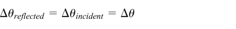
where the angle of incidence is θincident and the angle of reflection is θreflection .
Generally, ICF laser system uses a short pulse length (1–20 ns) which requires the mirrors in the laser system to be aligned precisely and to remain stable with that alignment in order to position the beams on target as desired. Tietbohi and Sommer 10 had pointed out that the misalignment (angular deviation) of transport mirrors can have a major impact on the beam position on target. Considering the Δ target as the deviation of beam position on target due to mirror rotation and ftarget as the focal length of target, we have

Regarding the transport mirror surface as a group of points on the surface,
Specifications of laser transport mirror.

Due to the stringent specifications, in practice, the assembly and alignment of ICF transport mirror is divided into two main steps to keep a higher cost-efficiency in optics assembly and maintenance:
Offline assembly and test in OAB. In the OAB, transport mirror and relative components are assembled into an optical LRU, measured and aligned to required accuracy.
Online assembly into the laser beam path at laser building. Based on the modularity of LRU, the transport mirror is assembled into switchyard with three standard joints, and only some calibrations of less complexity are necessary.
The center of this idea lies in that OAB is a specially designed laboratory for optics assembly where optics can be tested and measured precisely with strict cleanliness. Furthermore, LRU installation into laser beam also can be simulated and tested in OAB which will reduce the operation complexity of real installation at laser building very much. So, the challenges are in OAB. How to make the mirror align precisely remains difficult to realize. 11 In the following, with a fundamental analysis on the mounting and misalignment errors of transport mirror, we try to find a way to improve the performance of transport mirror assembly.
Error analysis of optical misalignment
As we have mentioned, the normal directional error of transport mirror has an important role on laser beam pointing accuracy and the surface form will affect the quality of laser beam. So, we will have a detailed discussion as follows.
The normal directional error of mirror surface
Traditionally, an assembly tolerance is dependent on how the tolerance chains are made up in the assembly. This includes some fundamental steps such as a description of the assembling relationships among parts, and then, modeling the mathematical equations of those variations in assembly dimensional chains. Most commonly used method of tolerance accumulation is as follows. Assume a three-dimensional (3D) chain as 12

where N Σ represents the required assembly dimension and Ni represents the dimensions of parts in dimensional chain. Then, if we denote δ Σ as the tolerance of N Σ and δi as the tolerance of Ni , we have

As shown in Figure 4, we know that for a reflecting plane, the tip-tilt error (angular error) is the central problem. The transport mirror unit is installed into laser beam path by the three ball-shaped joints which means the three-joint plane (Δ123) is the reference datum for mirror misalignment error. So, the angular error (Δθ) between the normal line of mirror surface and the normal line of plane (Δ123) is the one should be reduced to minimum. It is required below 60 μrad. Considering the fact that manufacturing tolerances of most parts in transport mirror are far more than 50 μm, reducing the items in tolerance chain, for instance, using more strict manufacturing tolerances, cannot meet the requirements of transport mirror alignment cost-efficiently. Considering a method to control the required geometric feature (angular deviation) directly, if we can measure the angular deviation precisely and adjust it to the minimum, it is possible to maintain the misalignment of mirror within the requirements. That is what we try to do in the following.
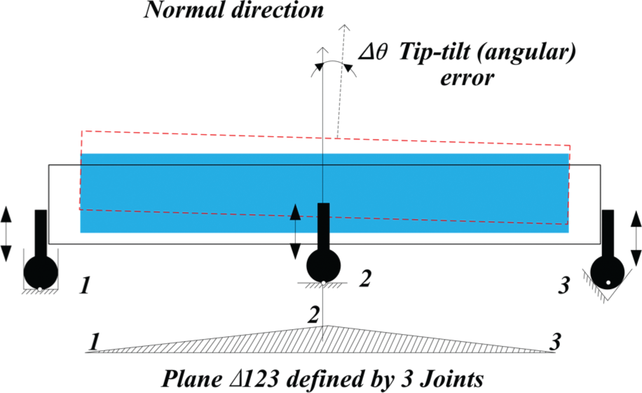
Misalignment error of transport mirror.
Surface form evaluation under mounting loads
The performance of mirror surface form will affect the quality of laser beam. In its assembly design, the mirror is held by an array of bolts and each provides a small tighten pressure on the K9 material mirror. However, considering the impact of tightening loads on surface deformation, it needs a delicate balance. Too much pressure will lead to a large deformation unaccepted; by contrast, smaller pressure may lead to instability during assembly, transport, operation, and maintenance because of mechanical vibrations. 10 Mechanical model to analyze the mounting performance and a comprehensive assessment based on the model are necessary. Let us consider the static mechanical model of mounted transport mirror. When it is assembled in the frame, the mirror is tightened by nearly 100 bolts at all sides, and it is also tightened by a rectangular pressing plate at the margins of coated reflecting surface. So, the mechanical model of mirror mounting can be simplified as a rectangle block with fixed bottom edges, upper edges under a uniform pressure, and all sides under fastening preloads. As shown in Figure 5, we can assume the boundary conditions as follows:
Boundary conditions of loads:
At the upper edges (L), uniformly distributed linear pressure σy =−P.
At all sides of mirror, the preload of each bolt is Pi = constant {i = 1, 2, …}.
Boundary conditions of displacements:
At the bottom edges (S), there are X S = 0, Y S = 0; Z S = 0.
We have the differential equation for the bending of a plate (Lagrange equation)


Schematic boundary conditions under mounted transport mirror.
where p(x) is the loads distributed on the plate surface and D is the bending stiffness of the plate. Gravity is also an important factor that needs attention in this model. We know the simply supported mirror has the maximum distortion at the surface center. Due to the stringent specifications on mirror surface aberration (only several hundred nanometers), the gravity-induced distortion can do much contribution to the surface distortion of large-aperture mirror. 13 Furthermore, if we consider the impact of mirror surface manufacturing (grinding and polishing) error, little margin is left for us, so the mirror surface aberrations have to be controlled very strictly.
Case study and discussions
Above discussions provide a general vision to the alignment performance evaluation of transport mirror. And based on the discussions, for a deep understanding on the proposed methodology and more technical improvements on transport mirror assembly, a real case of laser transport mirror (as shown in Figure 6) is provided. We know that geometric tolerances (or errors) and accumulation of components can lead to an obvious misalignment error (angular deviation of surface normal) for the transport mirror unit. During previous field work, a huge gap exists between the state-of-the-art engineering capacity and technical requirements even with most careful assembly operations. So, to control the angular deviation of mirror surface within the requirements, we need a method which can measure the angular deviation precisely and adjust it to the minimum. That is the motivation why we design an experimental assembly station with precise operations under a loop of online measurement–assembly adjustment to improve the performance of transport mirror. The simulated assembly station for transport mirror is designed to execute all the tasks of mirror’s installation, measurement, and adjustment on one platform. By precise optical inspection instruments and careful manual operations, the misalignment error (tip-tilt error) of transport mirror can be reduced to an acceptable level. A schematic design solution of the proposed assembly station is shown in Figure 7(a), which is for the transport mirror horizontally placed; generally speaking, the mirrors usually are placed horizontally, at 45° or vertically. The simulated assembly station has same assembly joints and positioning references as the structures in real laser beam path, so the transport mirror can be installed on the station by three standard ball-shaped joints as it does in laser building. As a result, simulated installation at the station will produce same result as the mirror’s installation at real laser beam path in laser switchyard. If we can reduce the mirror’s misalignment error to an acceptable level, the mirror’s installation at real laser beam path will meet the required specifications. Additionally, a reference reflector installed into the station has been already calibrated. When to use the position and orientation of the reflector should be calibrated by using the optical autocollimator and reference mirror. Then, the transport mirror to test can be installed into the assembly station. And using the optical autocollimator, we can measure misalignment error of the mirror surface placed horizontally precisely. If the misalignment error is not within the specifications, we can adjust the three ball-shaped joints to make angular error between the normal of three-joint plane and the normal of mirror surface to lower. Table 2 shows the results of initial experiments. The angular deviation of normal line of mirror surface is measured (denoted as Δxθ and Δyθ as shown in Figure 8), which represent the projections of real angular deviation (Δθ) on two datum planes, Y = 0 and X = 0. Considering the angular deviation is very small (close to zero), we have

So we know

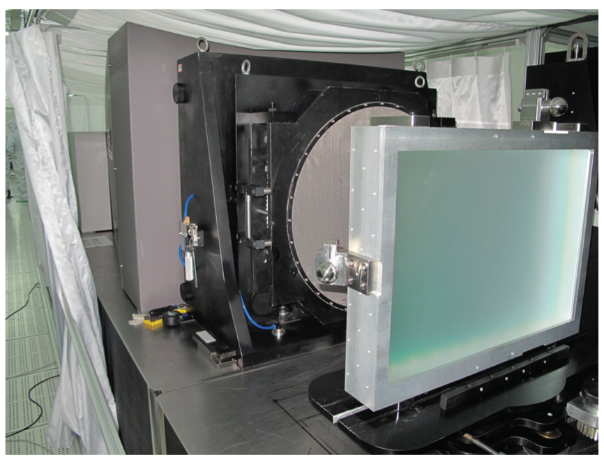
A case of 400 mm aperture transport mirror.

The simulated assembly station for transport mirror: (a) schematic diagram and (b) field test.
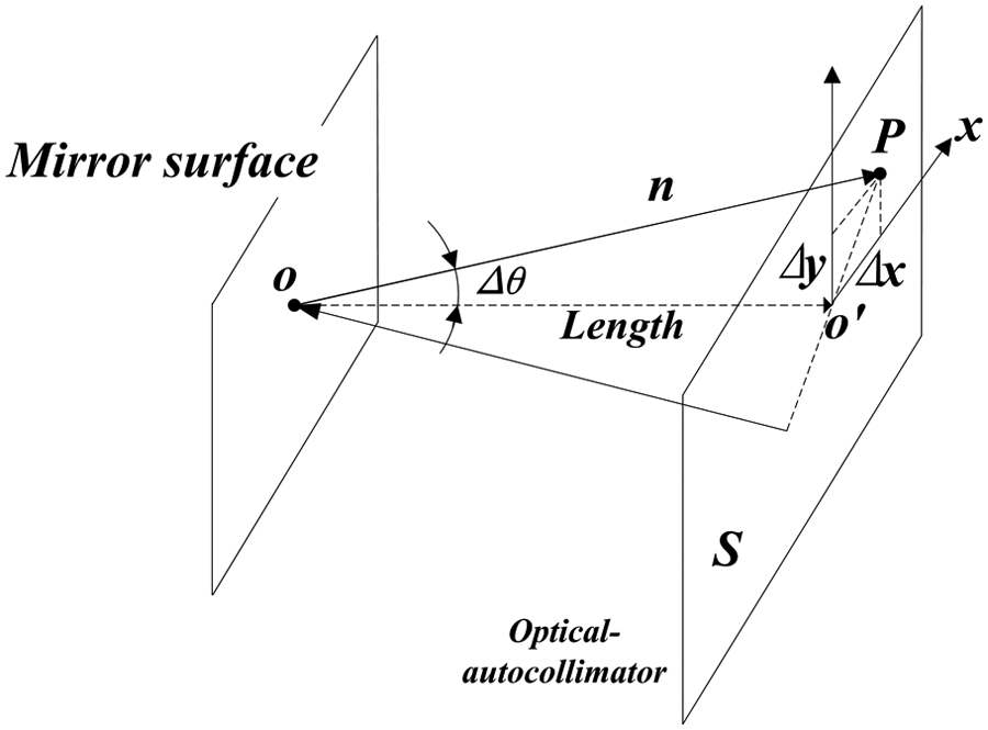
Measuring the misalignment error (Δθ) of mirror surface.
Misalignment error of transport mirror surface.

So, the simulated assembly station provides us an integrated system to measure the performance of transport mirror’s alignment precisely.
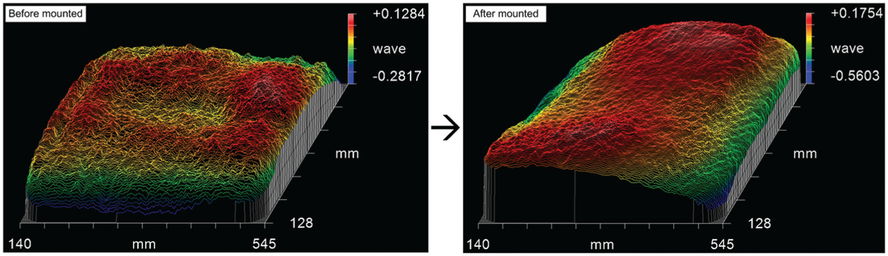
Another problem needs attention is the distortion of mounted mirror surface. Methods that integrated opto-mechanical and finite element analysis have been widely used in this kind of problems.14,15 Based on the mechanic model mentioned above, simulation and calculation problems of the mirror surface deformation can be solved by using ANSYS workbench (R15) and MathWorks MATLAB (R2011). Detailed results are shown in Figure 9; the pressure on upper edge is 2000 N and mirror is placed horizontally. We also can get the gravity-induced distortion under three most frequently used orientations: 0°, 45°, and 90°, as shown in Figure 10. The maximum of gravity-induced distortion can be 0.1 μm when placed horizontally. Considering the gravity-induced deformation and mount-induced deformation obey the superposition principle, we have the peak-to-valley (PV) of mount-induced deformations (400 mm aperture optical window) 0.19 μm at 160 N, 0.15 μm at 130 N, and 0.11 μm at 100 N, respectively. According to SG-III system’s specifications, the deformation (PV) of mounted mirror surface should be within λ/3 = 211 nm. So ideally, single fasten preload cannot be more than 160 N. Considering the real case of transport mirror shown in Figure 6 where it is measured by a Φ600 mm near-infrared interferometer, combined impact of mounting loads, gravity, and polished surface error will make the surface aberration much more than λ/3. Actually, field tests show that surface aberration (PV) of mounted mirror is nearly 465 nm, as shown in Figure 11. This means even 160 N/each fasten is higher. Less will be better. However, real tightening loads also cannot be less because the mirrors in high-power laser system should be aligned precisely and remain stable with that alignment under external ambient vibration input. Therefore, large-aperture transport mirrors are usually designed to be extremely stable in the vibration and thermal environment so that all laser beams can hit the target (∼250 μm focal spot) with a precision of better than 30 μm (RMS) from numerous directions almost at the same time.

Surface deformation of mounted mirror: (a) preload = 160 N/each fasten, (b) preload = 130 N/each fasten, and(c) preload = 100 N/each fasten.

Gravity-induced deformation: (a) horizontal placement, (b) 45° placement, and (c) vertical placement.
Surface measurement with near-infrared interferometer.
So, a crucial problem is to find out the balance between conflicting goals, higher stability, and less distortion. That means we need to reduce the tightening loads without much impact on system stability. A possible method is to increase the coefficient of friction between mirror and fastens. So, an interlayer among the mirror and fastens (as shown in Figure 12) is proposed to use. Two types of low-stiffness materials, polytetrafluoroethylene (PTFE) and specially treated copper alloy, are used to test. The coefficients of friction are measured in field experiments and results show that the coefficients of friction between PTFE/aluminum alloy and PTFE/K9 glass are 0.05–0.1, the coefficient of friction between copper and aluminum alloy is 0.4–0.5, and the coefficient of friction between copper and K9 glass is 0.5–0.7. It is evident that the specially treated copper alloy is more reliable to use as interlayer between fastens and mirror. Two prototypes of mirror units using PTFE and specially treated copper alloy as interlayers are made and measured in the following assembly and misalignment tests.

The interlayer for mirror tightening.
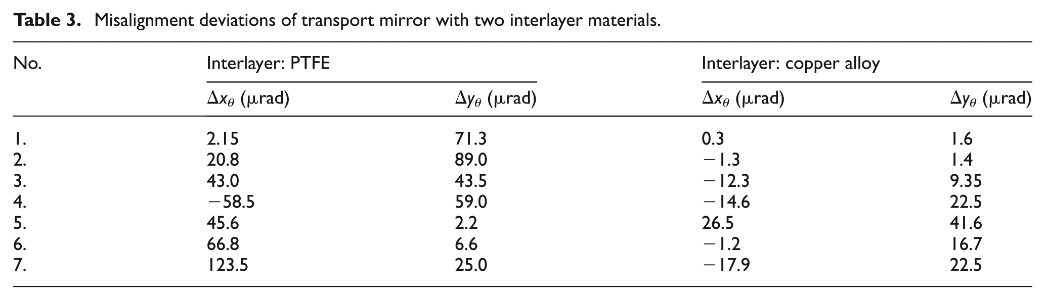
Focus of field tests is on the stability performance of mirrors under ambient vibrations. Generally speaking, installed mirrors in the target area building will be subjected to low-level ambient vibrations (the peak of power spectral density (PSD) less than 1 × 10⁻¹⁰g2/Hz) from external sources, and much more vibration and shock also exist during transport and installation. In field tests shown in Figure 13, accelerometers were used to record data of vibration and shock on the transport way. The data can create a time history of acceleration and turned into an acceleration PSD for further vibration analysis. And displacement sensors are also used to detect the motions between the mirror unit and big frame where the mirror unit is installed by three ball-shaped joints. Motions are very possible to occur at the joints during transport. Both of numerical simulation and field measurements have been done to verify our design improvement. First, with ANSYS analysis of static structural, modal, and random vibration, the numerical results reveal that with the interlayers in mirror design, 110 N of per-fastener preload is enough for mirror tightening whose specifications require the angular deviation of mirror surface below 60 μrad. Second, after repeated transport tests, the mirror units are placed back to the simulated assembly station (as shown in Figure 7) to inspect the tip-tilt error of optical surface. The measured results tabulated in Table 3 represent the capacity of mirror unit to remain stable under ambient vibrations. From Table 3, we know, for the mirror unit with PTFE interlayer: RMS(θ) ≈ 26 μrad, and for specially treated copper alloy interlayer: RMS(θ) ≈ 17 μrad. The results indicate two significant achievements of new design for mirror mounting. On one hand, with the new design of simulated assembly station, the misalignment error of mirror surface can be measured and adjusted very precisely. So, it provides us a method and platform to reduce the misalignment error to the required level. And meanwhile, experimental data also show a robust performance of repositioning accuracy using interlayer of specially treated copper alloy. It is same with our expectations. So, with proper parameters, we can control the misalignment errors of transport mirror within the required 60 μrad, and furthermore, with the 110 N per-fastener preload for mirror tightening, the mount-induced surface distortion also has a noticeable improvement (surface PV less than 0.2 μm). All of them indicate a significant progress to meet the stringent specifications of laser beam.
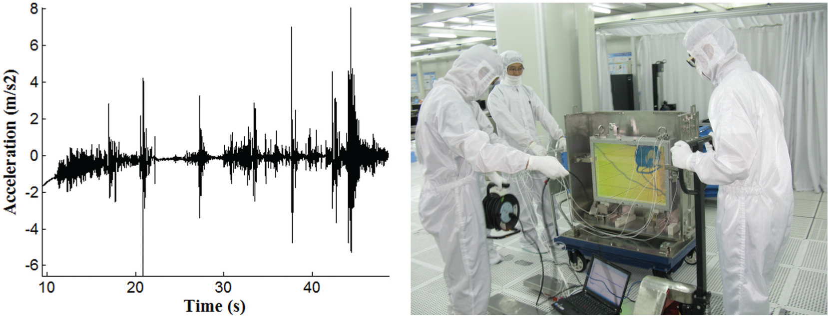
Measuring the vibrations and shocks of transport mirror unit.
Misalignment deviations of transport mirror with two interlayer materials.
Conclusion
The misalignment and profile errors of large-aperture transport mirror have very crucial impacts on the performance of ICF laser beam. To control the errors in required specifications, we have a detailed investigation on the error accumulation process of mirror with theoretical modeling and numerical analysis. By a new design of adding interlayer between mirror and fastens, higher coefficient of friction can make the mirror more stable in the ICF environment, while the surface deformation is also controllable. And a simulated assembly station for transport mirror is proposed to provide an efficient method to measure the misalignment of mirror surface precisely and reduce it by online adjustments. Experimental studies show an obvious improvement in the performance of laser transport mirror and validate our proposed methodology to control the misalignment to stringent specifications, including mount-induced surface deformation error smaller than 0.22 μm and misalignment error within 60 μrad. Furthermore, this study also provides a more general philosophy combining the parametric opto-mechanical methods and field studies to predict and evaluate the performance of ICF large precise optics in some very extreme and special conditions.
Footnotes
Acknowledgements
The authors gratefully acknowledge the support and contributions of our colleagues in the Research Center of Laser Fusion, China Academy of Engineering Physics.
Academic Editor: Duc T Pham
Declaration of conflicting interests
The authors declare that there is no conflict of interest.
Funding
This research is also supported in part by National Natural Science Foundation of China (grant no. 51205221).