
Abstract
The energy loss coefficient, relating directly to the energy dissipation ratio, is an important index of this energy dissipater. In this article, this coefficient and its affecting parameters were analyzed by theoretical considerations, and their relationships were obtained by numerical simulations. It could be concluded that the energy loss coefficient of sharp-edged orifice plate and its backflow region length were mainly dominated by the contraction ratio of the orifice plate. Sharp-edged orifice plate’s energy loss coefficient and its backflow region length all increase slightly with the increase in its thickness. When Reynolds number is in the range of 9.00×10⁴–10.3×10⁶, Reynolds number has little impacts on energy loss coefficient and backflow region length. Two empirical expressions, relating to backflow region length and energy loss coefficient, respectively, were presented.
Keywords
Introduction
The orifice plate, as a kind of energy dissipaters with sudden reduction and sudden enlargement forms, has been used in large-scale hydropower projects successfully.1–3 As early as 1960s, a plug dissipater, similar to orifice plate in energy dissipation mechanism, was used in the flood discharge tunnel of the Mica dam in Canada; the flow velocity of the flood discharge tunnel was decreased from 52 to 35 m/s at the head of 175 m.4,5 In the Xiaolangdi hydropower project in China, three orifice plates in the flood discharge tunnel obtained the energy dissipation ratio of 44% and controlled effectively the flow velocity through the gate less than 35 m/s under the condition of the head of 145 m.6–8 Orifice plate has a wide application prospect in practical engineering.9–11
The flow through sharp-edged orifice plate is shown in Figure 1. There exist the vortex regions of ring form before and after the sharp-edged orifice plate due to the sudden reduction and sudden enlargement of the orifice plate, and those vortices are the original regions of the energy dissipation, especially the backflow region after sharp-edged orifice plate is the main key source of energy dissipation.12–14 Many researches were conducted on the energy dissipaters with sudden reduction and sudden enlargement forms.14–17 The interesting areas have been focused on orifice plate’s incipient cavitation number, embodying its cavitation risk, and its energy loss coefficient, relating to its energy loss ratio.17–19 Previous researches20–24 show that the energy loss coefficient and incipient cavitation number were closely related to orifice plate’s contraction ratio (β), defined as the ratio of the orifice diameter (d) of the energy dissipater to the diameter (D) of flood discharge tunnel. Qu et al.21,22 regarded that energy loss coefficient and incipient cavitation number increase with the decrease in contraction ratio. The orifice plate’s other geometric parameters also have slight impact on its incipient cavitation number. 24 Cai and Zhang 24 deemed that sloping-approach orifice plate is effective in improving the orifice plate cavitation performance, compared with the sharp-edged and square-edged orifice plates. However, sloping-approach orifice plate is inferior to the other two in energy dissipation ratio.

Flow through sharp-edged orifice plate.
As stated above, the researches conducted in the past focused mainly on the trend relationship between contraction ratio and energy loss coefficient or incipient cavitation number.25–28 As a matter of fact, the length of backflow region Lb (as shown in Figure 1) after orifice plate is an important parameter; not only it is closely related to orifice plate’s energy dissipation efficiency but also it is a valuable reference parameter when designing the distance between two orifice plates in multi-stage orifice plates.29–32 The purposes of this work, therefore, are to investigate the effects of the geometric parameters, that is, the contraction ratio and the sharp-edged orifice plate thickness, and the hydraulic parameters, that is, Reynolds number on the energy loss coefficient and backflow region length when the top angle φ is 60°, and to present empirical expression of the energy loss coefficient and the backflow region length to relating parameters, by means of numerical simulations.
Numerical simulations
Numerical simulation model
The commercial package FLUENT RNG k–ε model was selected to calculate the hydraulic parameters of the flow through the orifice plate, due to its suitability for simulating the flow inside large change boundary forms as well as its high precision and calculation stability. For the steady and incompressible flows, the governing model equations include continuity, momentum, and the k–ε closure.15–17 The control volume method and staggered grid are employed. The basic equations are integrated over each control volume to obtain the discrimination equations. The pressure implicit with splitting of operator (PISO) method is used to solve the velocity and pressure field. The main difference between PISO and the well-known SMPLE method is the second adjustment used in PISO. The block-off method is adopted to treat the control volumes occupied by the orifice plate so that the variables in these control volumes keep equal to 0 throughout the whole computation.
The calculation boundary conditions are treated as follows: in the inflow boundary, the turbulent kinetic energy kin and the turbulent dissipation rate εin can be defined, respectively, as
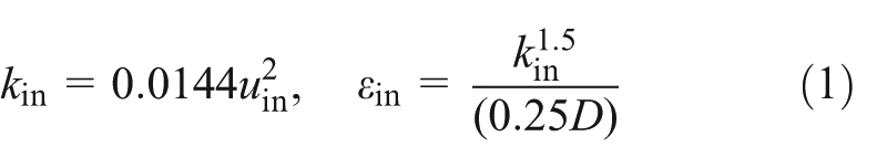
where uin is the average velocity in the inflow boundary. In the outflow boundary, the flow is considered as developed fully. The wall boundary is controlled by the wall functions. The symmetric boundary condition is adopted, that is, the radial velocity on symmetry axis is 0.
Given an orifice plate discharge tunnel has axial symmetry characteristics, three-dimensional numerical simulations of the orifice plate discharge tunnel flow can be simplified as two-dimensional ones.
Numerical simulation methods and phases
The energy loss coefficient of sharp-edged orifice plate can be defined as follows 15

where Δp is the pressure difference between the section before 0.5D orifice plate, in which flows are undisturbed, and the section after 7.0D orifice plate, where flows already recover; 15 ρ is the flow’s density; u is the flow’s average velocity in discharge tunnel. There are many parameters that affect the energy loss coefficient ξ and the backflow region length Lb (shown as in Figure 1) of sharp-edged orifice plate, and the relevant parameters of dimensional analysis may include the following: the density of water ρ (kg/m3), the dynamic viscosity of water μ (N s/m2), the tunnel diameter D (m), the orifice plate diameter d, the orifice plate thickness T (m) (as shown in Figure 1), the average flow velocity in tunnel u (m/s), and the pressure difference Δp (Pa). The top angle φ also has effects on energy loss coefficient ξ and the backflow region length Lb, but in order to consider structure safety, 60° top angle is adopted in general in practical engineering, so the case of 60° top angle is only investigated in this article. Because each of the above parameters is a function of the initial independent parameters, the expression of the above parameters can be obtained

This relationship could be rewritten in terms of dimensionless parameters

That is

where Re is the Reynolds number Re = uD/(μ/ρ); a is the orifice plate dimensionless thickness, a = T/D; β is the orifice plate contraction ratio, β = d/D; lb is the dimensionless backflow region length, lb = Lb/D. Equation (9) implies that the energy loss coefficient ξ and the dimensionless backflow region length lb are the function of β, α, and Re. The study procedure was outlined considering variable parameters in the energy loss coefficient and dimensionless backflow length variations in equation (5) in order to find out the effects of each parameter independently on them (i.e. ξ and lb).
According to the above analysis, two kinds of calculation phases were simulated and their phases are as follows: Phase No. 1, to calculate the energy loss coefficient ξ and the dimensionless backflow region length lb at the range of Reynolds number Re = 9.00×10⁴–2.76×10⁶ when β = 0.50 and α = 0.25, in order to analyze the effects of Re on ξ and lb; Phase No. 2, to calculate the energy loss coefficient ξ and the dimensionless backflow region length lb at the different β and α when Re = 1.80×10⁵, to discuss the variations in the energy loss coefficient ξ and the dimensionless backflow region length lb with β and α and to establish the relationship expression of them.
The calculation diameter (D) of the tunnel is 0.21 m. The range of the numerical simulations was selected at 6.0D before the sharp-edged orifice plate at the beginning and at 6.0D after the sharp-edged orifice plate at the end. The energy loss coefficient ξ is calculated by equation (9). The method to determine backflow region length is as follows: taking a section along tunnel direction, which is very close to the tunnel’s wall; viewing the flow’s horizontal velocity at this section; regarding the distance between orifice plate front and the point, where flow’s horizontal velocity is 0, as the backflow region length.
Numerical simulation results
The results of Phase No. 1 and Phase No. 2 are shown in Tables 1 and 2, respectively.
Variations in lb and ξ with Re (β = 0.50, α = 0.25).

Variations in ξ and lb with β and α (Re = 1.8×10⁵).

Discussions
Effects of Reynolds number
Table 1 presents the numerical simulation results of the dimensionless backflow region length after the sharp-edged orifice plate lb and Reynolds number Re and of the energy loss coefficient of the sharp-edged orifice plate ξ and Re when the contraction ratio β = 0.50 and the ratio of the dimensionless thickness α = 0.25. It could be seen that the energy loss coefficient ξ and the dimensionless backflow region length lb increase with the increase in Reynolds number Re when Reynolds number Re is less than 105 and are constants approximately when Reynolds number Re is in the range of 9.00×10⁴–10.3×10⁶. And they changed from 3.18 to 3.20 and from 31.97 to 32.06, respectively, with regard to the changes in Reynolds number Re from 9.00×10⁴ to 10.3×10⁶. Therefore, it could be concluded that the effects of Reynolds number Re could be neglected on either the energy loss coefficient ξ or the dimensionless backflow region length lb when Re is from 9.00×10⁴ to 10.3×10⁶, that is to say, lb and ξ are only the functions of the geometric parameters of the sharp-edged orifice plate, that is, β and α, when Re is in the range of 9.00×10⁴–10.3×10⁶. This conclusion agrees with the experiment. 15
Effects of thickness and contraction ratio
Table 2 presents the numerical simulation results of the dimensionless backflow region length after the sharp-edged orifice plate lb and of the energy loss coefficient of the sharp-edged orifice plate ξ when the contraction ratio β varies from 0.40 to 0.80 and dimensionless thickness α varies from 0.05 to 0.25. It can be learned that the energy loss coefficient ξ and the dimensionless backflow region length lb increase with the decrease in the contraction ratio β, but dimensionless thickness α has little impact on both the energy loss coefficient ξ and the dimensionless backflow region length lb, that is, when α is 0.10, the energy loss coefficient ξ increases from 1.68 to 90.18, and the dimensionless backflow region length lb increases from 1.41 to 3.56 with regard to the changes in the contraction ratio β from 0.80 to 0.40; when β is 0.50, although the dimensionless thickness α changes from 0.05 to 0.25, the energy loss coefficient ξ, which is approximately 32.51, and the dimensionless backflow region length lb, which is approximately 3.23, are almost constant. From the above analysis, Reynolds number Re and the dimensionless thickness α hardly affect both the dimensionless backflow region length lb and the energy loss coefficient ξ in the simulation scope; their impacts on them could be neglected, and then equation (5) can be expressed as

Figure 2 is drawn using the data in Table 2 when dimensionless thickness α (a = T/D) is 0.10 and Reynolds number Re is 1.8×10⁵, which embodies the relationship between the contraction ratio β and the dimensionless backflow region length lb. If neglecting the impacts of Reynolds number Re and the dimensionless thickness α on the dimensionless backflow region length lb, the empirical expression of the dimensionless backflow region length lb, by means of fitting the curve in Figure 2, could be obtained
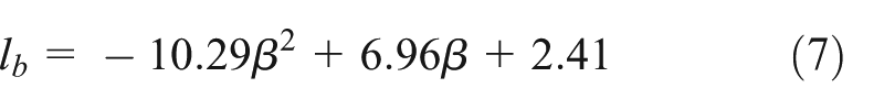

Relationship between β and lb.
This expression is valid for β = 0.4–0.8, α = 0.05–0.25, φ = 60° and Re = 9.00×10⁴–10.3×10⁶.
Similarly, Figure 3 is drawn using the data in Table 2 when dimensionless thickness α (a = T/D) is 0.10 and Reynolds number Re is 1.8×10⁵, which embodies the relationship between the contraction ratio β and the energy loss coefficient ξ. The empirical expression of the energy loss coefficient ξ if neglecting the impacts of Reynolds number Re and the dimensionless thickness α on it, by means of fitting the curve in Figure 3, could be obtained
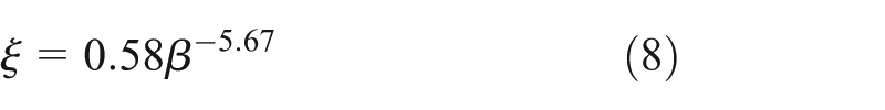

Relationship between β and ξ.
The above expression is valid for β = 0.4–0.8, α = 0.05–0.25, φ = 60° and Re = 9.00×10⁴–10.3×10⁶.
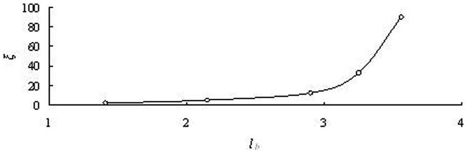
Figure 4 introduces the turbulence dissipation rate when Reynolds number Re is 1.8×10⁵, dimensionless thickness α (a = T/D) is 0.10, and contraction ratio β is 0.70. Figure 4 demonstrates that the backflow region after sharp-edged orifice plate due to the sudden reduction and sudden enlargement of the orifice plate is the main original region of the energy dissipation. Figure 5 shows the effects of the dimensionless backflow region length lb on the energy loss coefficient ξ, which was drawn by means of the data of Table 2. The energy loss coefficient ξ is, obviously, not bigger than 1.69 when the dimensionless backflow region length lb is less then 1.42 for dimensionless thickness α (a = T/D) being 0.10, while it increases rapidly when the dimensionless backflow region length lb is bigger than 1.69 for this dimensionless thickness α (a = T/D). It should be noted that the appearance of those results is also related to the dimensionless backflow region height hb. The height increases with the decrease in the contraction ratio β on the basis of hb = (1 − β)/2. Since the water volume of the backflow region after the orifice plate has cubic relation of characteristic parameter D, the combination of the backflow region length and height makes this water volume change greatly.
Turbulence dissipation rate (Re = 1.8×10⁵, a = 0.10, β = 0.70).

Relationship between lb and ξ.
Verification
In order to verify the rationality of equation (8), the comparison results between model experiment data measured by Zhang and Cai 33 and the data calculated using equation (8) are shown in Figure 6. From Figure 6, it can be seen that the results calculated using equation (8) are approximately equal to those obtained by the experiment, and the relative errors of equation (8) are all less than 10%.

Comparison between experiment data and calculated data.
Conclusion
For a sharp-edged orifice plate energy dissipater, its energy loss coefficient ξ and its dimensionless backflow region length lb after it are all the function of the contraction ratio β, the dimensionless thickness α, and the Reynolds number Re of the flow on the basis of equation (5). And the effects of Re and α are weak and could be neglected on the ξ and lb when Re is in the range of 9.00×10⁴–10.3×10⁶.
The contraction ratio β, which brings about the effects on the energy loss coefficient ξ through the magnitude and the length of the backflow region, is the key factor that dominates the energy loss coefficient ξ. The smaller is the contraction ratio β, the bigger is the energy loss coefficient ξ. The relationship between ξ and β could be expressed as equation (8). Compared with the numerical simulation results and the model experimental results, the relative errors of equation (8) are all less than 10%.
Footnotes
Appendix 1
Academic Editor: Chun-Liang Yeh
Declaration of conflicting interests
The author(s) declared no potential conflicts of interest with respect to the research, authorship, and/or publication of this article.
Funding
This article was funded by CRSRI Open Research Program (Program SN:CKWV2015216/KY)