
Abstract
A three-dimensional solid–fluid conjugated model is used to investigate and optimize the performances of two-, three-, and four-layered microchannel heat sinks. In the optimization process, constraints of fixed total pumping power and fixed total channel height are adopted, and the thermal resistance and bottom wall temperature uniformity are taken as the objective functions. The flow configuration, channel height, and pumping power in each layer are optimized. The results show that more uniform temperature distribution and lower thermal resistance occur at flow configuration (0, 1) for the two-layered microchannel heat sink, (0, 1, 1) for the three-layered microchannel heat sink, and (0, 1, 1, 1) for the four-layered microchannel heat sink. The channel height and pumping power in the bottom layer are dominant over those in the other layers. The optimal design requires a smaller bottom channel height and a higher pumping power than the average value in each layer. The multilayered microchannel heat sink with more layer numbers can achieve a more uniform bottom wall temperature and can also lead to a reduction in the thermal resistance.
Introduction
With the advances in microelectronic mechanical system (MEMS) technology, the sizes of microelectronic devices become more and more compact, and their power becomes higher and higher. This results in tremendous increases in the power densities and associated heat fluxes generated in these devices. Thus, effective methods for heat removal become indispensable for the thermal management of MEMS. Microchannel heat sink (MCHS) is one of the most important cooling methods of micro devices due to their advantageous heat transfer performance such as compact size, smaller volume per heat load, lower coolant requirements, and lower operational cost, as compared with conventional heat sink. 1 However, there still exist many disadvantages including high pumping power requirement and poor uniformity of temperature distribution at the cooling surface. Recently, Xie and colleagues,2–6 Hajmohammadi et al.,7–12 and Wang and colleagues13–18 conducted many relevant works to improve the cooling performance of the MCHS. For example, Xie and colleagues2–6 studied the wavy MCHS and proposed some new MCHS structures with multistage bifurcations or with constructional vertical Y-shaped bifurcation plates. Hajmohammadi et al.7–12 optimized the structure of the heat sink and adopted power-law fluid as the coolant. In addition, the flow stability and the viscous dissipation effect in microchannels have been investigated using the semi-analytical method and gradient energy method in Hajmohammadi et al.,8,12 and these methods can also be used to study the flow stability in the MCHS.
To improve the cooling uniformity of the MCHS, Vafai and Zhu 19 for the first time proposed the design of two-layered MCHS. In the new structure, coolant flows reversely in the top and bottom channels for temperature compensation between the two channels, which leads to a lower pressure drop and a more uniform temperature distribution as compared with one-layered MCHS. Subsequently, many researchers carried out optimization studies on the two-layered MCHS,20–26 and the optimized parameters include the solid materials of heat sink, coolant, flow direction, channel shape and size, velocity ratio between two channels, and so on. Based on the various designs of the two-layered MCHS, researchers further constructed multilayered MCHS. Wei and Joshi 27 adopted a three-dimension thermal resistance model with the box optimization algorithm to optimize the geometry parameters of multilayered MCHS. The effect of layer number on the heat sink performance was investigated in their work. It was found that the one-layered MCHS achieves the best performance with the pumping power of 0.01 W. Lei et al. 28 conducted an experimental study on the performance of cooper multilayered MCHS, and their results indicated that the thermal resistance of heat sink decreases with the increase in layer number, but the decrease degree becomes smaller. Afterward, Wei and Joshi 29 and Lei et al. 30 performed further studies on the influence of layer number on the performance of multilayered MCHS under various conditions.
It is worth noting that the multilayered MCHS in Wei and Joshi27,29 and Lei et al.28,30 is stacked by many single-layered MCHS with the same size; thus, the total height of the heat sink is not a fixed amount when the layer number varies. However, under real circumstances, only a very limited cooling space is available for assembling the heat sink. Moreover, the cooling load in each layer of the multilayered MCHS is different, so that different coolant flow rates or pumping power for each layer should be adopted. Unfortunately, the pumping power or coolant flow rate in each layer was assumed to be the same in Wei and Joshi27,29 and Lei et al.28,30
In this article, a three-dimensional solid–fluid conjugated model is developed to investigate the flow and heat transfer characteristics in the multilayered MCHS at a constant total pumping power of 0.05 W and a constant total channel height of 700 μm. The effects of flow configuration, channel height, and pumping power in each layer on the heat sink performance are analyzed, and the corresponding optimal values for these parameters are obtained.
Geometry and material properties for multilayered MCHS
The MCHS is made of silicon, and water is used as a coolant. The material property parameters are k s = 148 W m−1 K−1, k l = 0.613 W m−1 K−1, μ l = 0.000855 kg m−1 s−1, ρ l = 997 kg m−3, and c pl = 4179 J kg−1 K−1, where k is the thermal conductivity, μ is the viscosity, ρ is the density, and c p is the specific heat. The subscripts s and l denote solid rib and liquid coolant, respectively. The heat sink has a dimension of Lx × Lz × Ly = 10 × 10 × 0.9 mm3. The optimal geometric parameters for the one-layered MCHS have been obtained in our previous work. 13 For the purpose of comparison, the present multilayered MCHSs adopt the same parameters, such as channel number of N = 73, total channel height of H c = 700 μm, channel width of W c = 85 μm, and rib width of W r = 26 μm. Only one element is taken as the computational domain due to the symmetry of the heat sink, as shown in Figure 1.

Schematics of MCHSs: (a) one-layered MCHS, (b) two-layered MCHS, (c) three-layered MCHS, and (d) four-layered MCHS.
Thermal resistance and maximum bottom wall temperature difference are two important indicators to evaluate the cooling performance of the heat sink. The thermal resistance is defined as

where T max and T min = T in are the highest and lowest temperatures observed in the heat sink, and A = LxLz is the base area of the heat sink. The maximum bottom wall temperature difference is defined as

where T b,max = T max and T b,min are the maximum and minimum temperatures on the bottom wall.
Numerical model
The three-dimensional heat sink model adopts the following assumptions: (1) incompressible and laminar flow; (2) constant material properties of solid rib and coolant; (3) neglected gravity, viscous dissipation, and contact thermal resistance; and (4) no heat losses between the heat sink and ambient except the bottom wall of the heat sink. Because water is used as the coolant and its inlet Reynolds number is always lower than 500 for all simulation cases, the assumption of incompressible and laminar flow is reasonable. Our previous study 13 showed that constant material properties only lead to about 4% deviation of the thermal resistance compared with temperature-dependent properties. In addition, previous studies13,19,20 also indicated that the gravity and viscous dissipation can be safely ignored in microchannels. Although the contact thermal resistance between the heat sink and cooled surface deteriorates the cooling performance of the heat sink, its effect can be minimized using the heat-conducting adhesive with high thermal conductivity. The governing equations are descried briefly as follows:
Continuity equation for the coolant

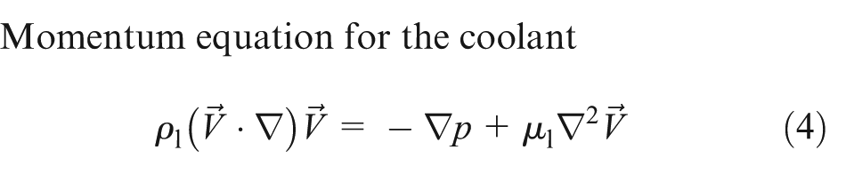
Momentum equation for the coolant
Energy equation for the coolant

Energy equation for the solid rib

where
The boundary conditions adopted are as follows: the coolant inlet temperature in each layer remains a constant value of T in = 293K; the outlet pressure in each layer is assumed to be 1.01325 × 10⁵ Pa; no-slip condition is specified to all channel walls; the coupled boundary conditions are adopted on the fluid–solid interface, that is, the temperature and heat flux are continuous on these interfaces; and adiabatic boundary condition is applied to the outside walls and symmetric surfaces. In addition, the simulations are performed at constant bottom wall heat flux of q w = 100 W m−2 and a constant total pumping power of Ω = 0.05 W.
The model uses nonuniform distributed grid. The present code is tested for grid independence by calculating the fluid temperature along the flow channel centerline. It is found from Figure 2 that a grid size of 40 × 45 × 40 for the two-layered heat sink ensures a grid-independent solution. For the other heat sinks discussed in this work, the grid independences are also examined in preliminary test runs.

Grid independence examination for the two-layered heat sink.
The experimental data of the two-layered MCHS reported in Wei et al.’s 22 study are used to validate the present model. The geometric structure and operating conditions of the heat sink are assumed to be the same with those in Wei et al. 22 Figure 3 shows the predicted and measured bottom wall temperatures for four coolant flow rates. The deviations between the predicted and measured results are less than 1K. Thus, the present model can be used accurately to predict the multilayered MCHS performance.

Model validation.
Results and discussion
Effect of flow configuration
Unlike the one-layered MCHS, the multilayered MCHS has multiple inlets and outlets. Previous studies21–23 have shown that the flow configuration in each layer affects the heat dissipation and temperature uniformity of the two-layered MCHS significantly. It can be expected that the flow configuration also affects the performance of the three- and four-layered MCHSs. In the present simulations, number 0 stands for the positive x-direction, while number 1 denotes the negative x-direction. Thus, when the flow configuration is taken as (0, 1, 0) for the three-layered MCHS, it means that the coolant flows along the positive x-direction in the bottom and top layers, while the coolant flows along the negative x-direction in the middle layer. It should be noted that the three-layered MCHS with flow configuration (0, 1, 0) or (1, 0, 1) has the identical performance due to the symmetry. Consequently, only flow configurations (0, 1) and (1, 1) for the two-layered MCHS; (0, 0, 0), (0, 1, 0), (0, 0, 1), and (0, 1, 1) for the three-layered MCHS; and (0, 0, 0, 0), (0, 1, 0, 0), (0, 0, 1, 0), (0, 0, 0, 1), (0, 1, 1, 0), (0, 1, 0, 1), (0, 0, 1, 1), and (0, 1, 1, 1) for the four-layered MCHS are investigated here. It is restated that a constant total pumping power of Ω = 0.05 W and a constant total channel height of H c = 700 μm are used in the present simulations. In this section, the pumping power and channel height in each layer are assumed to be the same, that is, Ω n1 = Ω n2 = ... = Ω nn = Ω/n and Hn 1 = Hn 2 = ... = Hnn = H c/n, where n denotes the layer number of the multilayered MCHS.
The thermal resistances and bottom wall temperature differences at various flow configurations for the one-layered and multilayered MCHSs are listed in Table 1. It can be seen that the flow configuration has a great influence on the multilayered MCHS performance. Taking the four-layered MCHS for example, when the flow configuration is changed from (0, 0, 0, 0) to (0, 1, 1, 1), the thermal resistance is reduced by 7.79%, and the bottom wall temperature difference is decreased by 45.4%. Among all the flow configurations, the thermal resistance and bottom wall temperature difference are the highest if the flow direction of the coolant in each layer is taken as the same, that is, (0, 0) for the two-layered MCHS, (0, 0, 0) for the three-layered MCHS, and (0, 0, 0, 0) for the four-layered MCHS. It is worth noting that the performances for flow configurations (0, 0), (0, 0, 0), and (0, 0, 0, 0) are even worse than those for the one-layered MCHS, indicating that only simple dividing of a one-layered MCHS into a multilayered MCHS cannot improve the heat sink performance.
Thermal resistances and bottom wall temperature differences at various flow configurations for the one-layered and multilayered MCHSs.

MCHS: microchannel heat sink.
Number 0 in the column of flow configuration denotes the positive x-direction, while 1 denotes the negative x-direction.
The best flow configuration is (0, 1) for the two-layered MCHS, (0, 1, 1) for the three-layered MCHS, and (0, 1, 1, 1) for the four-layered MCHS, which can reduce thermal resistance of the heat sink and improve the temperature uniformity on the bottom wall significantly (Table 1). Levac et al. 21 and Xie et al. 23 presented that for the two-layered MCHS with the same geometry and pumping power in each layer, the parallel flow is the best flow configuration to improve the cooling performance at low flow velocity, while the counter flow is the best one at high flow velocity, and it can always achieve a better temperature uniformity at both the low and the high flow velocities. Moreover, Levac et al. 21 pointed out that a critical Re for transition from the parallel flow to the counter flow is 100. In the present two-layered MCHS, the channel height and pumping power in the top and bottom layers are the same, the corresponding Re is 135.67 higher than the critical value reported by Levac et al.; thus, the optimal flow configuration should be (0, 1), which agrees well with the present simulation.
Figure 4 shows the temperature contours of the three-layered MCHS in the x–y middle cross section for various flow configurations. For flow configuration (0, 0, 0), the bottom wall temperature gradually increases along the flow path, and the highest temperature appears at the channel outlet with x = Lx ; hence, the temperature uniformity is the worst for this flow configuration. When the flow direction of the coolant for the middle layer and/or top layer is changed, the coolant in these layers will inevitably cool the bottom layer in the outlet region of the bottom layer due to lower coolant inlet temperature, which is referred to as the cooling effect. Conversely, a heating effect will be observed in the inlet region of the bottom layer because the coolant outlet temperature in the middle layer and/or top layer is higher than the coolant inlet temperature in the bottom layer. Thus, more uniform temperature distribution and lower thermal resistance occur for flow configurations (0, 1, 0), (0, 0, 1), and (0, 1, 1), and the best flow configuration for the three-layered MCHS is (0, 1, 1). Similarly, as long as the flow direction in the second, third, and/or fourth layer is changed for the four-layered MCHS, the performance can be improved, and the best performance will occur for flow configuration (0, 1, 1, 1).

Temperature contours of the three-layered MCHS in the x–y middle cross section (not to scale).
Figure 4 also indicates that the flow configuration affects the distribution of heat dissipation in each layer for the three-layered MCHS significantly. For all flow configurations (0, 0, 0), (0, 1, 0), (0, 0, 1), and (0, 1, 1), the outlet temperatures in the bottom layer are all higher than those in the middle and top layers, which means that the bottom layer dissipates most of the heat. The outlet temperature in the bottom layer is the highest for flow configuration (0, 0, 0) and then followed by (0, 1, 0), (0, 0, 1), and (0, 1, 1). For flow configuration (0, 1, 1), the outlet temperature is 301.81K for the bottom layer, 299.55K for the middle layer, and 298.84K for the top layer. The corresponding heat dissipations (=ρc p u in(T out − T in)) are 0.59, 0.43, and 0.39 W, respectively. As compared with the other three flow configurations, the heat dissipation in each layer is the most uniform for flow configuration (0, 1, 1). Table 1 shows that the thermal resistance has the same dependence on the flow configuration as the outlet temperature in the bottom layer. It can be concluded from the above results that when the geometry and pumping power in each layer are the same for a multilayered MCHS, the optimal cooling performance can be achieved by such a flow configuration which offers a more uniform heat dissipation in each layer.
Effect of channel height
This section discusses the effect of channel height in each layer on the multilayered MCHS performance. The flow configuration is assumed to be the optimal one obtained in section “Effect of flow configuration,” and the pumping power in each layer is equally distributed. The channel heights are investigated in the following order. Taking the three-layered MCHS for example, the bottom channel height H 31 first varies from 100 to 500 μm, while the middle and top channel heights remain as the same value of H 32 = H 33 = (700 − H 31)/2; once the optimal H 31 is obtained, the middle channel height starts to vary from 100 to 400 μm with the optimal (H 31)opt and H 32 = 700 − (H 31)opt − H 32.
Figures 5–7 show the dependence of thermal resistance on channel heights for the two-, three-, and four-layered MCHSs, respectively. For all simulation cases, the thermal resistance first decreases and then increases with the increase in channel height, indicating that each channel in the multilayered MCHS has an optimal height. The optimal channel heights for the multilayered MCHSs are listed in Table 2.
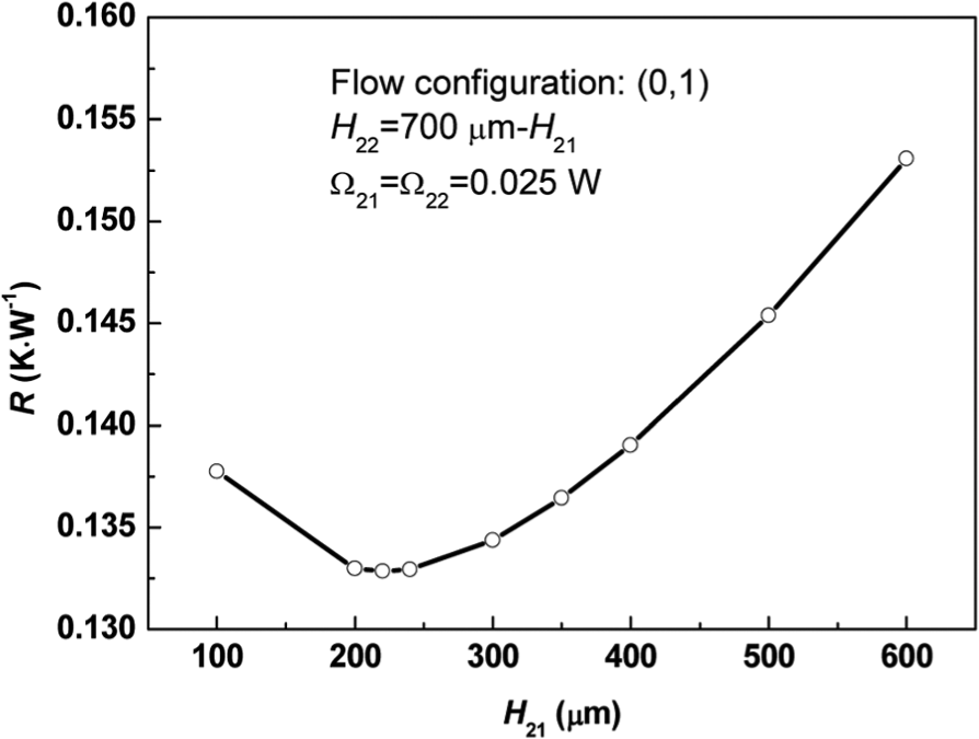
Effect of channel height on thermal resistance of the two-layered MCHS.

Effect of channel height on thermal resistance of the three-layered MCHS.

Effect of channel height on thermal resistance of the four-layered MCHS.
Optimal parameters for various multilayered MCHSs.

MCHS: microchannel heat sink.
Figure 8 shows the centerline temperature distribution on the bottom wall at various H 31 for the three-layered MCHS. It is restated that the pumping power in each layer remains the same in the present simulations. As a result, when the bottom channel height increases, the flow rate in the bottom layer increases, and hence, more heat will be dissipated by the bottom layer. For a very small channel height of H 31 = 100 μm, the middle and top layers dissipate much more heat than the bottom layer; increasing H 31 enhances the heat dissipation by the bottom layer and hence leads to a more uniform heat dissipation in each layer. Conversely, for a very large channel height of H 31 = 500 μm, more heat is dissipated by the bottom layer; thus, H 31 needs to be reduced to achieve a more uniform heat dissipation in each layer. Consequently, there certainly exists an optimal H 31, which can make sure that each layer dissipates almost the same heat. For the present simulation, the optimal H 31 is found to be 170 μm. As mentioned in section “Effect of flow configuration,” the uniform heat dissipation in each layer of the multilayered MCHS can lead to a low thermal resistance and a more uniform temperature distribution on the bottom wall. Thus, when H 31 = 170 μm, the heat sink has the lowest thermal resistance of 0.1351 W K−1 (Figure 6) and the most uniform bottom wall temperature distribution of ΔT b = 5.532K (Figure 8).

Temperature distributions on the bottom wall at various H 31.
A comparison of Figures 5–7 shows that the bottom channel height has more significant effect on the heat sink performance than the other channel heights. For example, the thermal resistance corresponding to the optimal H 31 = 170 μm is 0.1351 W K−1, which is reduced by 13.06% as compared with the maximum thermal resistance of 0.1554 W K−1 (H 31 = 500 μm). However, with the optimal H 31 = 170 μm, the thermal resistance corresponding to the optimal H 32 = 230 μm is 0.1350 W K−1, which is reduced by only 2.10% as compared with the maximum thermal resistance of 0.1379 W K−1 (H 32 = 100 μm). Moreover, Figures 5–7 and Table 2 show that the optimal bottom channel height is H 21 = 220 μm for the two-layered MCHS, H 31 = 170 μm for the three-layered MCHS, and H 41 = 160 μm for the four-layered MCHS, which is always smaller than the average channel height.
Effect of pumping power
This section analyzes the effect of pumping power in each layer on the multilayered MCHS performance. During the simulations, the optimal flow configurations in section “Effect of flow configuration” and the optimal channel heights in section “Effect of channel height” are adopted.
The pumping power for each layer is optimized in the same order as the channel height. Figures 9–11 show the dependence of thermal resistance on pumping power for the two-, three-, and four-layered MCHSs, respectively. For all simulation cases, as the pumping power increases, the thermal resistance always first reduces and then increases; thus, an optimal pumping power for each layer can be obtained (Table 2). The optimal pumping power in the bottom layer are Ω21 = 0.026 W for the two-layered MCHS, Ω31 = 0.022 W for the three-layered MCHS, and Ω41 = 0.02 W for the four-layered MCHS, which is always larger than the average pumping power; thus, the optimal design for the multilayered MCHS requires a higher pumping power in the bottom layer. In addition, Figures 9–11 also demonstrate that the pumping power in the bottom layer is dominant over the pumping powers in the other layers. For example, the thermal resistance for the optimal Ω41 = 0.02 W is 0.1361 W K−1, which is reduced by 7.36% as compared with the maximum thermal resistance of 0.1469 W K−1 (Ω41 = 0.005 W). However, when optimal Ω41 = 0.02 W is adopted, the thermal resistance for the optimal Ω42 = 0.013 W is 0.1356 W K−1, which is reduced by 3.00% compared with the maximum thermal resistance of 0.1398 W K−1 (Ω42 = 0.022 W). Similarly, when optimal Ω41 = 0.02 W and optimal Ω42 = 0.013 W are adopted, the thermal resistance for the optimal Ω43 = 0.009 W is reduced by only 1.56%.

Effect of pumping power on thermal resistance of the two-layered MCHS.
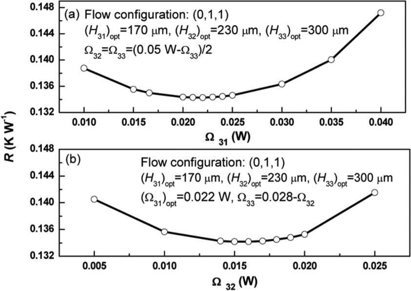
Effect of pumping power on thermal resistance of the three-layered MCHS.

Effect of pumping power on thermal resistance of the four-layered MCHS.
Figure 12 shows the heat flux distributions on the channel wall for the three-layered MCHS at three different Ω41 = 0.01, 0.022, and 0.04 W, which correspond to the three cases in Figure 10(a). Only the negative heat flux is shown in Figure 12. The negative heat flux means that the coolant temperature is lower than the rib temperature, so that the heat will be transferred from the coolant to the rib. Consequently, the negative heat flux has an unfavorable effect on the cooling performance of heat sink. As shown in Figure 12, the negative heat flux mainly occurs in the region of channel outlet. When Ω41 increases, the area of the negative heat flux is reduced for the bottom layer, while it is enlarged for the middle and top layers. As a result, there exists an optimal Ω41, which can balance the distribution of negative heat flux in the three layers and hence achieve the optimal heat sink performance.
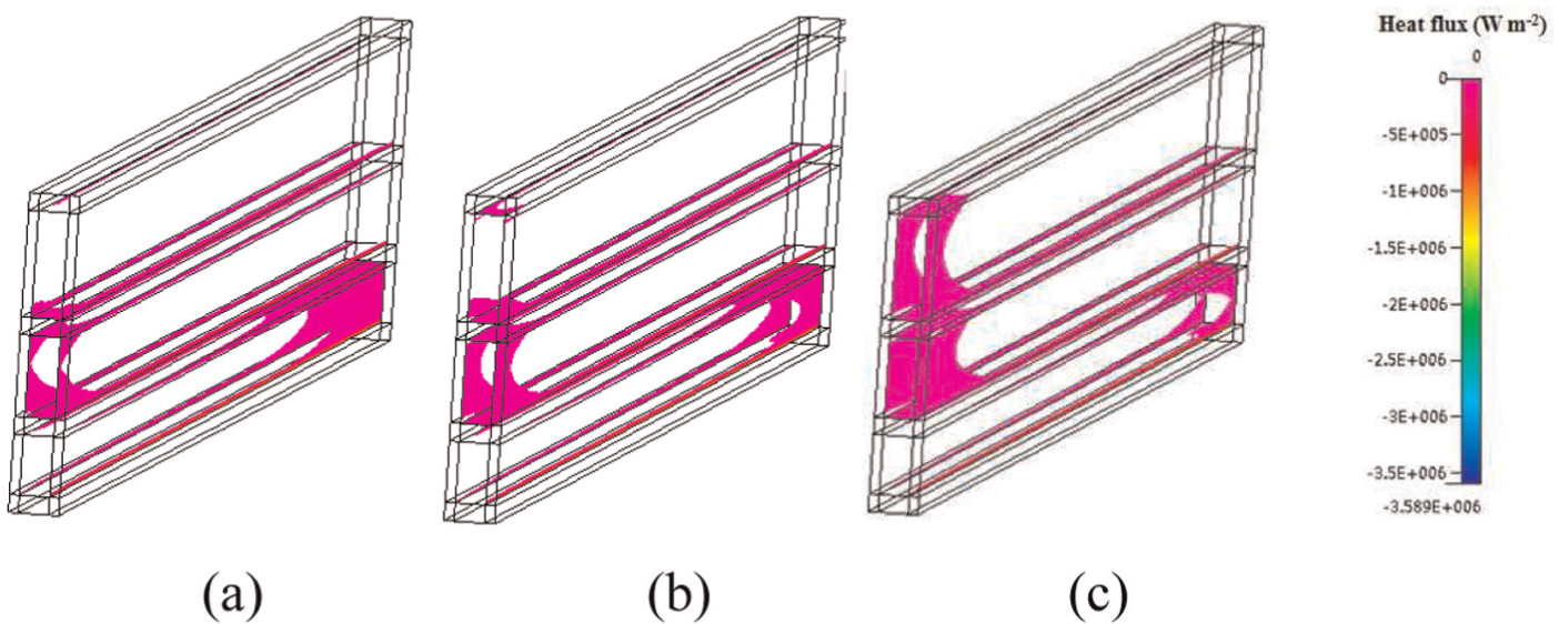
Areas of negative interfacial heat flux for various Ω31: (a) 0.01, (b) 0.022, and (c) 0.04 W.
Comparison of the optimal performance between one-layered and multilayered MCHSs
Table 2 shows the optimal parameters, the corresponding thermal resistance, and the bottom wall temperature difference for the two-, three-, and four-layered MCHSs, respectively. The thermal resistance and bottom wall temperature difference of the multilayered MCHSs are all lower than those of the one-layered MCHS. Among the multilayered MCHSs, the two-layered MCHS has the lowest thermal resistance of RT = 0.1328 W K−1; however, its temperature uniformity is the worst with bottom wall temperature difference of ΔT b = 6.21K. On the contrary, the four-layered MCHS can achieve the best temperature uniformity with ΔT b = 5.53K, but its thermal resistance is the highest (RT = 0.1356 W K−1).
Conclusion
In this work, a three-dimensional solid–fluid conjugate model is used to analyze the flow and heat transfer characteristics of the multilayered MCHSs at a constant total pumping power and a constant total channel height. The model is validated well by comparing the predicted bottom wall temperature with the experimental data. The flow configuration, channel height, and pumping power in each layer are optimized. The main conclusions are as follows:
The flow configuration has significant effect on the multilayered MCHS performance. Among all the flow configurations, the thermal resistance and bottom wall temperature difference are the highest if the flow direction of the coolant in each layer is taken to be the same, and they are even worse than those for the one-layered MCHS. The most uniform temperature distribution and the lowest thermal resistance occur at flow configuration (0, 1) for the two-layered MCHS, (0, 1, 1) for the three-layered MCHS, and (0, 1, 1, 1) for the four-layered MCHS.
For the multilayered MCHS, there exists an optimal channel height for each layer. However, the bottom channel height has more significant effect than the other channel heights, and the optimal bottom channel is always smaller than the average channel height.
Similarly, when the total pumping is fixed, each layer has an optimal pumping power to achieve the optimal heat sink performance. The pumping power in the bottom layer is dominant over the pumping powers in the other layers, and the optimal design requires a higher pumping power in the bottom layer than the average pumping power.
As the layer number increases, the multilayered MCHS can achieve a more uniform bottom wall temperature and can also lead to a reduction in the thermal resistance.
Footnotes
Academic Editor: Mohammad Reza Salimpour
Declaration of conflicting interests
The authors declare that there is no conflict of interest.
Funding
This study was supported by the National Natural Science Foundation of China (no. 51176010), the 111 Project (no. B12034), Program for New Century Excellent Talents in University (no. NCET-11-0635), and the Fundamental Research Funds for the Central Universities (no. 13ZX13).