
Abstract
Surface water source heat pump system is an energy-efficient heat pump system. Surface water heat exchanger is an important part of heat pump system that can affect the performance of the system. In order to enhance the performance of the system, the overall heat transfer coefficient (U value) of the water exchanger using a 32A square copper coiled high-density polyethylene tube was researched. Comparative experiments were conducted between the performance of the coiled high-density polyethylene tube and the 32A smooth high-density polyethylene tube. At the same time, the coefficient of performance of the heat pump was investigated. According to the result, the U value of the coiled tube was 18% higher than that of the smooth tube in natural convection and 19% higher in forced convection. The coefficient of performance of the heat pump with the coiled tube is higher than that with the smooth tube. The economic evaluation of the coiled tube was also investigated.
Keywords
Introduction
Nowadays, serious environmental problems cause people to pay more attention to energy saving and high efficiency equipment.1–5 Compared to the conventional air condition equipment, ground source heat pump (GSHP) is more efficient for heating or cooling commercial and institutional buildings and residential ones. Many researchers are focusing on this research area.
Esen and Inalli6,7 have researched the performance of horizontal and vertical GSHP systems. In the horizontal GSHP system, the coefficient of performance (COP) of the system at 1 m was 2.66 and the COP at 2 m was 2.81. In the vertical GSHP system, when the depths of borehole were 30, 60 and 90 m, respectively, the COPs of the system were 3.37, 3.85 and 4.33. In order to compare the performance between an air-source heat pump (ASHP) system and a reversible GSHP system, De Swardt and Meyer 8 conducted experiments and simulations for space heating and cooling. The use of municipality water reticulation system as a heat source or sink resulted in an annual improvement of 14% in the COP. Especially, the low ambient air temperature GSHP system has 20% efficiency improvement over the ASHP system. Urchueguia et al. 9 showed an experiment between a ground coupled heat pump system and a conventional air-to-water heat pump system, focusing on the energy performance of heating and cooling modes. The results obtained were that the geothermal system saved a 43%±17% of the energy consumed by the conventional one in heating mode and a 37%±18% in cooling mode.
Surface water source heat pump (SWSHP) is a type of GSHP which extracts heat from a lake or a river. As an important part of the SWSHP system, surface water heat exchanger (SWHE) can affect the COP of the total heat pump system. At present, the high-density polyethylene (HDPE) tube is used widely as the heat exchanger tube. However, it has low thermal conductivity (0.4 W/m K). In order to increase the overall heat transfer coefficient (U value), Jung et al. 10 came up with a grooved HDPE tube used as the heat exchanger. In the research, a fin-effect and cross-sectional area loss-effect with a square grooved HDPE tube for increasing the U value of SWHE were proposed. Diversified ideas about increasing the performance of SWHE are needed, because not only the shape of the tube but also the material of the tube affects the U value. When the heat pump system uses a metallic tube with high thermal conductivity as the SWHE, the length of the tube can be reduced and the pumping head will be well utilized. However, the corrosion affects the metallic tube and brings out the problem of sustainability.
In this study, in order to enhance the U value, the HDPE tube wound with rectangular copper wire was proposed. It can not only improve the U value but also prevent corrosion. In addition, it can increase the COP of the SWSHP and reduce the life cycle cost. Then, a comparative experiment between the coiled HDPE tube and the smooth one was conducted.
The study aims to use the new type of the SWHE tube to improve the performance of the SWSHP system. The economic evaluation of the coiled tube was analysed in order to investigate whether it can save the energy consumption and reduce the environment problem. In addition, in this study, the results of the experiments were compared with the results of study of Jung et al. 10
Theoretical heat transmission in tube
U value of the heat exchanger was analysed in this research. There were two ways to calculate the U value, and the two values were called experimental U value and calculated U value, respectively.
Experimental U value
Equations (1)–(6) show the experimental U value calculation process. 11 At first, the mean temperature difference (MTD) between inlet and outlet water in the tube was calculated and used to verify the heat transfer rate. Then, the U value was calculated by calculating heat transfer rate of the heat exchanger and the logarithmic mean temperature difference (LMTD) between water in the tube and water outside the tube


Calculated U value
In general, when water temperature gradient inside and outside of the tube is not significant, the heat transfer produced by thermal radiation can be ignored. Instead, it is enough to consider only the thermal convection and thermal conduction.
In the calculated U value calculation process, heat transfer was divided into three parts: (1) heat convection between water in the tube and inner wall of the tube, (2) heat convection between water outside the tube and outer wall of the tube and (3) conduction of the tube. The thermal resistances of the three heat transfer processes were explained by the Reynolds number (Re), Prandtl number (Pr), Nusselt number (Nu), Raleigh number (Ra), and Grashof number (Gr), which are calculated using equations (7)–(18). Re is defined in equation (7). When Re < 2300, the flow is laminar, and from Re ≥ 10,000, it is perceived to be turbulent. In the tube, Nu is calculated by equation (8) in laminar and by equation (9) in turbulent flow. Outside of the tube, external Nu can be calculated using equation (11) in forced convection and equation (12) in natural convection. The sum of the three resistance values was used as the total thermal resistance. This sum was used in the calculation of the U value (equations (19)–(21)11,12)


Friction factor and fouling factor
The friction factor can be calculated according to equation (22). Correlation between Re and the friction factor was calculated using equations (23) and (24) 13


Fouling factor can affect the U value of real stare SWHE in long-term operation. Thus, Rreal should be calculated at real state tube where the fouling factors (Rfi+Rfo) are considered. According to equation (25), the Rreal was calculated 13

Experimental work and uncertainty analysis
Sample preparation
There were two SWHE tube samples prepared in this study. Sample A was made by 32A smooth HDPE tube, with thickness of 5 mm and length of 24.54 m. Sample B was made using the square copper coiled HDPE 32A tube.
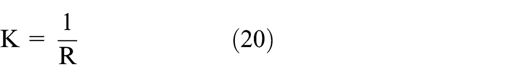
In order to conduct comparative experiment, the HDPE tube with 24.54 m long and 32 A, 5 mm thick and thermal conductivity of 0.4 W/m K was grooved. The groove in the tube was 2.5 mm width and 1.0 mm depth with pitch distance of 7.0 mm. The grooved tube was wrapped with a square copper wire with width of 2.5 mm and height of 3.5 mm. The thermal conductivity of the copper is 400 W/m K, 1000 times the conductivity of the HDPE. After processing, the increase in the surface area was 78.5%, and there was no reduction in volume. Figure 1 shows sample B and the detail of two sample tubes.
Detail of square copper coiled tube.
Preparation of the experiment
Figure 2 shows the experiment system. In the experiment system, there were two double water tanks, 1RT heat pump, 1RT refrigerator and circulating pump with pumping head of about 49.033 kPa and maximum flow of 60 L/min, and the water tanks, heat pump and SWHE tubes were connected by a 25 A tube line system.

Schematic diagram of experimental system.
In double water tanks, the internal water tanks (0.8 × 1.2 × 1.5 m), filled with chilling water, were used for cooling the heat exchanger tube, and the external water tanks were used to maintain the internal water temperature through circulating chilling water. The temperature of chilling water in the external water tanks was maintained by two chilling systems. One system was the evaporator of the heat pump connected to the external water tanks by 25 A copper tube and the other one was the refrigerator, also connected to the external water tanks.
The warm water was maintained by a condenser. The condenser of the heat pump was connected to the heat exchanger. For the forced convection, there was one water pump in each internal tank, and the water in external tanks was circulated continuously during the experiment.
Uncertainty analysis
Electronic flow meter was used to measure the flow rate and the temperature was measured by a 28-channel data logger with K-type thermocouples. The power consumption of the heat pump compressor was measured by a watt-hour meter. The pressure of the inlet and outlet warm water was measured by pressure gauges with range of 0–0.01 MPa.
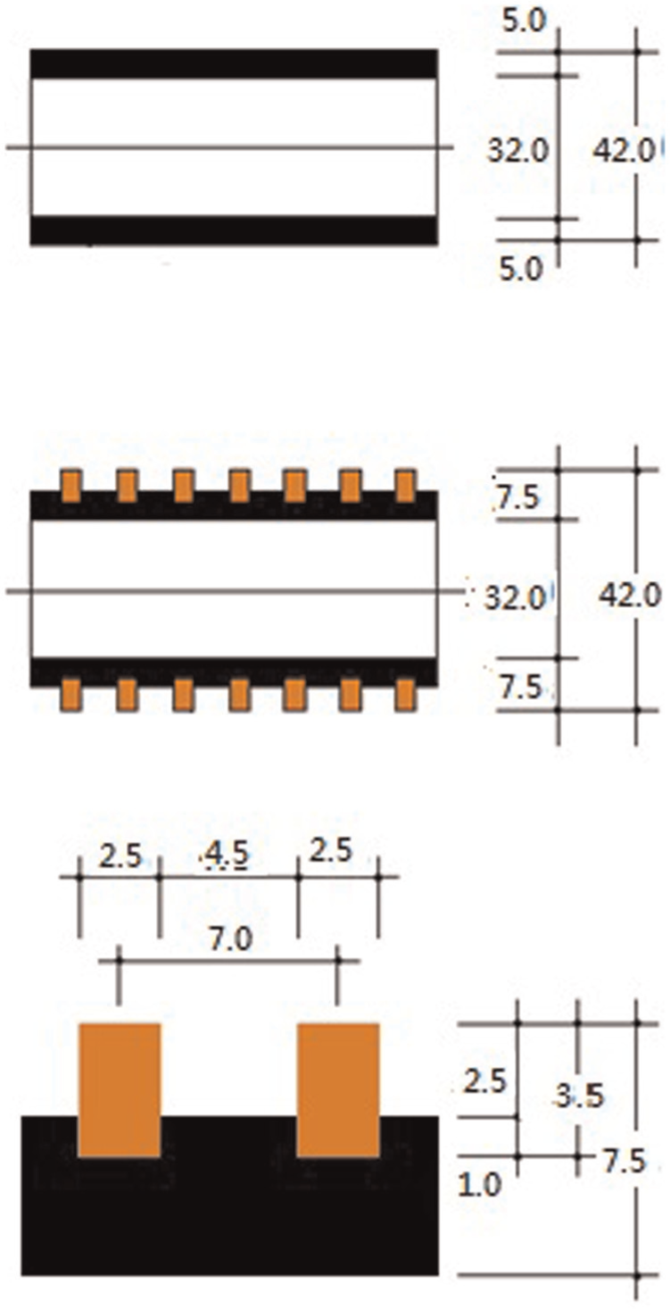
The uncertainty error of overall heat transfer coefficient is estimated from the measured data and the accuracy of the instruments used in the experiments. The uncertainties in the measured quantities for this study were estimated to be ±0.1 °C for the temperature measured by K-type thermocouples and ±2% for the flow measured by electronic flow meter. Uncertainty analysis has been in the engineering literature since Kline and McClintock’s 14 study, which has been widely cited. In this study, following the uncertainty propagation analysis, 15 the uncertainties for the deducted experimental results for U value were estimated as follows: 7.50%−10.13% for the U value in cases of a smooth tube and 7.28%−9.45% in cases of a coiled tube (Table 1). These errors are considered to be inconsequential to the results of the experiment. Nevertheless, as shown in the previous chapter, this experiment system is a tank-and-tube exchange system. In this study, only the uncertainty of the tube side was considered relevant and the data required for the uncertainty analysis for the tank side were not collected.
Overall heat transfer coefficient calculation uncertainty.
SD: standard deviation.
Testing
The experiments were conducted from 11 January to 28 April 2014 in the Architectural Environmental Laboratory at Pukyong National University, Yongdang-dong, Busan, Korea.
In order to investigate the performance of heat transfer process, the U value of the smooth tube (32A HDPE tube) was compared to the coiled tube (32A square copper coiled tube), and the COPs of the SWSHP of the different samples were investigated.
In the study, there were four different cases according to the water condition in internal tanks. They were (1) smooth tube in natural convection, (2) smooth tube in forced convection, (3) coiled tube in natural convection and (4) coiled tube in forced convection. During forced convection, the velocity of water in internal water tanks was set at 0.1 m/s using a water pump as an agitator.
In this study, only the cooling mode was used. Before any experimental measurement, the temperature of chilling water into the compressor was set at 12 °C±1 °C. When the temperature of the cooling water in inlet part of sample tubes reached a certain value, the experimental measurement started. The velocity of cooling water was set at 0.6, 0.7 and 0.8 m/s in order to match the velocity of the cooling water of around 0.7 m/s flowing in the SWHE in the practical project. The velocity of chilling water was kept at 1. m/s. Before the experiments, the temperature of water in internal tank was maintained at 20 °C. The indoor temperature was kept at 25 °C±1 °C, and the indoor relative humidity was kept at 35%±5%.
The temperature of warm water at the inlet and outlet of the tube was measured every 1 s. The temperatures of internal water tank at lower, middle and higher portion were also measured every 1 s. In order to calculate the COP of the heat pump, the inlet and outlet temperatures of chilling water were measured at the same time. The experiment was done for 30 min at each velocity of warm water. About 10 min of thermal equilibrium at the measuring temperature was provided before obtaining the meaningful datasets. At the beginning and end of the test, the flow rates of the warm water and chilling water were recorded to obtain the total flow rate in 30 min. The amount of effective flow was calculated using the amount of water at the inlet and outlet of the tube, doubling these values, and converted them into flowing rate per hour. The pressure of inlet and outlet of the heat exchanger and the compressor power consumption of the heat pump were measured in the beginning and end of the test.
Results and discussion
U value of smooth tube
According to equations (7)–(21), the calculated U value of the smooth tube was obtained. For the warm water with velocity of 0.7 m/s, the internal thermal resistance Rhi of the smooth tube due to the natural convection was 0.00291 K m/W. The external resistance Rho of the smooth tube was 0.01266 K m/W. The thermal resistance of the tube Rc was 0.108254 K m/W. The sum of these three resistances was the total thermal resistance R with the value of 0.123824 K m/W. For the warm water with velocity of 0.7 m/s, internal thermal resistance Rhi of the smooth tube at forced convection was 0.00291 K m/W. External resistance Rho of the smooth tube was 0.00689 K m/W. Thermal resistance of the tube Rc was 0.108254 K m/W. The sum of these three resistances was the total thermal resistance R with the value of 0.118054 K m/W. As a result, the total thermal resistance in natural convection was higher than in forced convection. This procedure was repeated as the velocity of the warm water changed from 0.6 to 0.8 m/s.
Using equations (1)–(6), the experimental U value was also calculated. Table 2 shows the calculated and experimental U values under each experimental condition. Comparing the two values, the experimental U value was 4%−7% lower than the calculated value in natural convection and 1%−4% lower in forced convection. The small difference can be regarded as an experimental error.
LMTD, heat transfer, U value of smooth tube and coiled tube under each condition.

LMTD: logarithmic mean temperature difference.
U value of coiled tube
The U value of the coiled tube was calculated according to equations (1)–(7). During the calculation procedure, the LMTD, the heat transfer rate and the surface of the tube were calculated.
The U value of the coiled tube ranged from 64.0 to 68.4 W/m2 K with the velocity of warm water varying from 0.6 to 0.8 m/s in natural convection. In forced convection, the value ranged from 72.8 to 76.8 W/m2 K. The U value of the coiled tube in forced convection was higher than in natural convection. The ratio of increase was 8%−10%.
Comparison between coiled and smooth tube
In order to understand the improvement of the performance of the coiled tube, the U values of the two tubes were compared. As a result, the average U value of the coiled tube was 18% higher than the smooth tube in natural convection and 19% higher in forced convection. In the study on a grooved HDPE tube by Jung et al., 10 the U value of the grooved tube was 21.5% higher than the smooth tube in natural convection, and 23.5% higher than the smooth tube in forced convection. The coiled tube has shown high average U value, similar to the grooved tube, even though there was no cross-sectional area loss with the coiled tube. The average U value of the coiled tube was slightly lower than that of the grooved tube with high depth fin. Therefore, the comparison confirms the effects of the outer fin, the inner corrugation and fin type (material, size) of copper coiled tube. Figures 3 and 4 show the relationship between U value and Re, and the U value increased with the increase in Re.

U value against Re in natural convection.

U value against Re in forced convection.
Friction factor and fouling factor of coiled tube
The friction factor was analysed in a previous study on heat transfer performance of a grooved HDPE tube. The convective heat transfer of the inner surface and outer surface of the smooth tube was verified using Nu. Experimental errors of resistances of convections and conduction in the tubes were calculated using the difference between calculated U value and experimental U value. Thus, in this study, the friction factor was analysed in the same way.
In the calculation of experimental friction factors of the smooth tube, the equivalent length of fittings was applied as follows: the quantity of elbow was 45, the quantity of branch was 1, length of connection tube was 1.95 m and the length of linear test tube was 24.54 m. Consequently, the applied total length of the tube was calculated as 119.19 m. The experiment results of the friction factors of the smooth tube were calculated by equation (22). The results were verified by using equations (23) and (24). Standard deviations between calculated and experimental friction factors of the inner surface of the tube were 0.00031 in natural convection and 0.000033 in forced convection, respectively.
The average friction factor of the coiled tube was 33% higher than the smooth tube in natural convection and 44% higher than the smooth tube in forced convection. The average friction factor of the coiled tube was higher than that of the grooved tube in natural and forced convection, but the difference of average friction factors between the coiled tube and grooved tube was insignificant. The difference in the friction factors can be assumed to be caused by the slight corrugation of the coiled tube, due to the deformation caused by the grooving and coiling process of the tube. On the other hand, as shown above, the average U value of the grooved tube was higher than that of the coiled tube. The comparisons of the friction factor and U value confirm that the fin-effect of the grooved tube is higher than that of the copper coiled tube.
According to equation (25), the Rreal can be calculated. Fouling factor in the tube and heat source or sink, such as a river, were each 0.00001 K m2/W, respectively. In the study, fouling resistance Rf = (Rfi/Ai)+(Rfo/Ao) is 0.00175 K m/W, 1.4% of total resistance R = 0.12328 K m/W of a clean tube.
COP of SWSHP

The COP of the SWSHP was calculated using equation (26). The power consumption was measured during the experimental period. As a result, the power consumption reduced when the velocity of warm water increased. When the velocity of warm water was increased from 0.6 to 0.8 m/s, the power consumption of the heat pump with the smooth tube was 1170.73–1130.30 W in natural convection and 1192.71–1162.54 W in forced convection. When the velocity of warm water was increased from 0.6 to 0.8 m/s, the power consumption of the heat pump with the coiled tube was 1158.80–1139.84 W in natural convection and 1150.77–1131.48 W in forced convection. The increase in the U value of the heat exchanger can lower the power consumption.
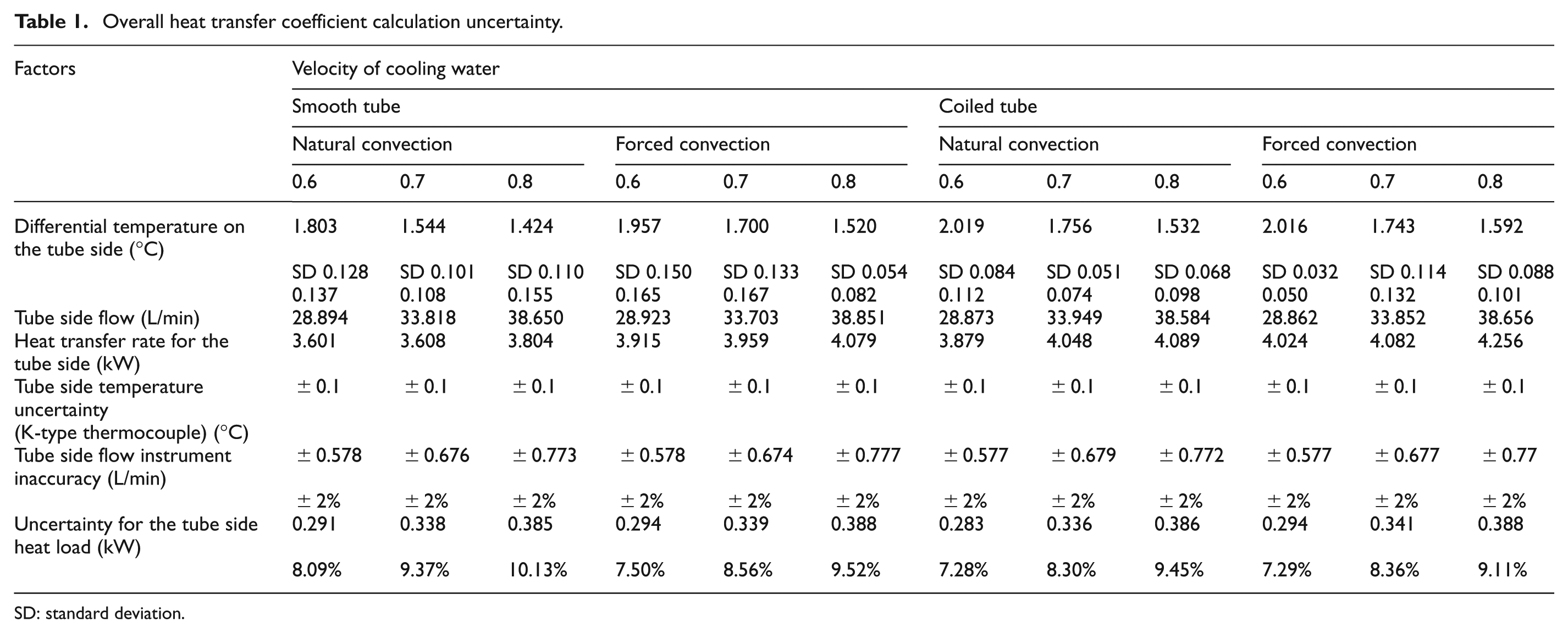
In the natural convection, the average temperature of supplied warm water was 40 °C in smooth tube and 39.6 °C in coiled tube. The COPs of the smooth tube were 1.80 at 0.6 m/s, 1.91 at 0.7 m/s and 1.83 at 0.8 m/s, and for the coiled tube were 2.50 at 0.6 m/s, 2.65 at 0.7 m/s and 2.63 at 0.8 m/s. Thus, compared with the smooth tube, the COP of heat pump with the coiled tube average increased to 40.5%.
In forced convection, the average temperature of supplied cooling water was 38.8 °C in the smooth tube and 38.4 °C in the coiled tube. When the velocity of cooling water increased from 0.6 to 0.8 m/s, the COPs of the smooth tube were 2.17, 2.19 and 2.12, respectively, and the COPs of the coiled tube were 2.83, 2.99 and 3.04. The average increment rate was about 36.8%. Figures 5 and 6 show the results of the COP.
COP of SWSHP in natural convection.
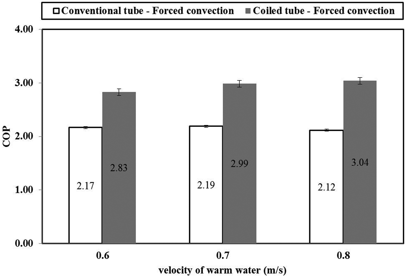
COP of SWSHP in forced convection.
In the research by Jung et al., 10 the COP of the grooved tube was 19.9% higher than the COP of the smooth tube in natural convection and 17.0% higher than that of the smooth tube in forced convection.
When comparing the U values of the grooved tube and coiled tube, the increment rate of the grooved tube was higher than that of the coiled tube. However, the COP of the coiled tube was higher than the COP of the grooved tube.
The reason is that electricity consumption of WSHP with the coiled tube is lower than the consumption of WSHP with the grooved tube even though the coiled tube has higher resistance than the grooved one in the same condition.
Economic evaluation of coiled tube
Table 3 shows cost of the coiled tube in SWHE. Cost saving of the material in SWHE with the coiled tube was calculated for economic evaluation. In determination of length with 32A HDPE tube for 1 RT refrigerator system, the length of the smooth and coiled tubes was each found to be 25.58 m per RT. The unit price of the smooth tube was US$1.47 per meter, and the unit price of the coiled tube was US$6.72 per meter in the Korean market. The price of copper wire per metre was about US$ 0.39, and 1 m HDPE tube needed about 10.63 m of square copper wire to make the coiled tube. The total copper price was around US$4.20. The manufacturing cost of the coiled tube was US$1.25. The material costs of the smooth and grooved tubes were calculated to be US$37.6 and US$171.90 per RT, respectively. Therefore, the material cost of the grooved tube was 357% higher than the cost of the smooth tube in SWSHP system.
Cost of coiled tube.

COP: coefficient of performance.
In the calculation of annual power cost saving of circulation pump and compressor in the coiled tube system, the method of simple estimation was used. The assumed factors were applied on running power consumption. In forced convection, the COP of the smooth tube was about 2.19 and the coiled tube was about 2.99 (LMTD, 20 °C; the fluid velocity, 0.7 m/s). The unit pressure drop of the smooth tube was 0.024 MPa and the unit pressure drop of the coiled tube was 0.034 MPa. And the annual running time was 1460 h, and the average load factor was 0.65. The unit price of electricity power for residential buildings in Korean market was US$ 0.72 kW−1 h−1.
As a result, the power consumption of circulation pump with the coiled tube was 10% higher than with the smooth tube. However, power of compressor with the coiled tube was 27% lower than with the smooth tube. Using the smooth tube, the annual power consumption was 1612.39 kW h/RT, and using the coiled tube it was 1214.07 kW h/RT. The annual running power cost with the smooth tube was US$1160.92 per RT, and for the coiled tube it was US$874.79 per RT. Therefore, the annual electricity power consumption with the coiled tube is 25% lower than the smooth tube in this research. In this case, the payback period is about 0.47 years.
Compared with the coiled tube, the making of the grooved tube 10 costs less money, because after grooving the tube, the coiled tube was wounded with the expensive copper wire. However, the strength of the coiled tube is higher than that of the grooved tube, and the payback period is short. In addition, the COP of WSHP with the coiled tube is over two times of WSHP with the grooved tube. Therefore, the coiled tube can be used in actual project.
Conclusion
In the experiment, the U value and COP were calculated to explain the performance of the SWSHP. The velocity of warm water varied from 0.6 to 0.8 m/s in the experiment. According to the results, the U value of the coiled tube was higher than the U value of the smooth tube in natural and forced convection condition, and the rate of increase was about 18% and 19%, respectively.
The increase in U value improved the heat transfer rate. At the same time, it also reduced the power consumption of the heat pump. As a result of COP calculation, the COP of SWSHP with the coiled tube was 41% higher than the COP of SWSHP with the smooth tube in natural convection and 37% higher in forced convection. The improvement of the U value of the SWHE can enhance the COP of the SWSHP distinctly. Consequently, it was found that HDPE tube wounded with square copper wire will definitely contribute to the energy saving in heat pump system.
According to the calculation of economic evaluation, the cost of material and manufacturing was about US$171 per RT. It was 357% higher than the cost of the smooth tube. In addition, the cost of electricity used by the smooth tube was US$1160.92 and US$874.13 with the coiled tube. The saving rate was about 25%. Therefore, when using the coiled tube as the SWHE, the invested capital is paid back in 0.47 years.
Footnotes
Appendix 1
Academic Editor: Cheng-Xian Lin
Declaration of conflicting interests
The authors declare that there is no conflict of interest.
Funding
This work was supported by Basic Science Research Program through the National Research Foundation of Korea (NRF), funded by the Ministry of Education, Science and Technology (2013R1A1A2009592).