
Abstract
Mandible defects and its deformities are serious complications and its precise reconstruction is one of the most challenging tasks in oral maxillofacial surgery. The commercially available standard mandible implants are manually bended before surgery to custom fit the patient’s jaw. A slight mismatch in the plate and bone alignment may result in the implant failure. However, with the integration of computer-aided design, rapid prototyping, and advanced imaging systems (computed tomography or magnetic resonance imaging), it is possible to produce a customized mandible implant that can precisely fit the patient’s jaw. The aim of this article is to compare a new design of customized mandible implant (sinewave plate) and compare it with the commonly used straight implant design. The finite element–simulated results reveal that the commonly used straight reconstruction plates are more prone to loosening of the screws due to its higher strain concentration on the screw hole when compared to newly designed sinewave reconstruction plate. Moreover, the straight plate is more sensitive to the chewing load variations and develops almost 20% increase in the stresses when compared to sinewave plate. The study reveals that the sinewave reconstruction plate can significantly enhance the stability and safety of the mandible implant.
Keywords
Introduction
In the maxillofacial region, mandible defects are caused by various reasons such as tumor, osteomylitis, trauma, and congenital defects such as hemifacial, microsomia, and Pierre Robin sequence. 1 Mandible plays an important function in the support of dental and para-dental processes such as mastication, articulation, deglutition, and respiration. Segmental mandibular resections without reconstruction will lead the mandible to deviate to the resected side, which leads to functional loss and a major cosmetic deficiency. Each year, thousands of people undergo mandible reconstruction surgery using titanium (Ti)-based implants which is one of the most suitable biocompatible materials.2–5
From the past one decade, the majority of commercial mandible implants have been processed using casting, forging, machining, and powder metallurgy techniques.6,7 The main problems with the commercially available titanium implant (mandible) plates are their standard size and style. As each patient’s physique and bone structure are different from others, the commercially available titanium implant plates are either bigger or smaller making it difficult to surgically implant the mandible in the resected region. The implant needs manual bending or machining before and during surgery using trial-and-error methods to custom fit the patient’s jaw, and surgeons need to spend a considerable amount of time to fit the plate to the contours of the patient’s bone. Moreover, the conventional manufacturing processes used for the implants put extra constraints on mandible design and this is one of the reasons that most of the existing mandible designs are restricted to straight plate. The integration of computer-aided design (CAD), rapid prototyping (RP), and advanced imaging systems (computed tomography (CT) or magnetic resonance imaging (MRI)) allows for the development of patient-specific (customized) physical implants of any complex structure for use in a surgery.8–10 Using RP technology (e.g. electron beam melting (EBM)), a customized mandible implant can be produced according to the topology constructed from the patients’ CT/MRI scan. The pre-operative RP-produced customized implants can drastically decrease mandible implant failure and reduce the number of revisions, thus reducing the psychological stress and pain of the patients and reducing the surgical time and medical cost. 11
This study presents a comparative study of two structurally different customized designs of mandible by using finite element (FE) method. FE analysis plays an important role in the designing of the implant reconstruction plate12–14 and is widely employed in biomechanical studies to simulate the mechanical behavior of the mandible implant.15,16 One of the customized design is the equivalence of the commonly used straight plate design and the other is the newly developed customized sinewave pattern design. The sinewave pattern was chosen based upon the fact that it might act as a better scaffold for overlying soft tissue than the straight plate and also provide increased surface area for osseointegration of the bone graft to the plate. The assessment of the two designs is achieved by focusing on the performance parameters such as stress, strain, and load sensitivity. The main aim of this study is to suggest an improved customized design compared to the commonly used customized straight design using FE method.
Methodology
Figure 1 shows the major steps in the methodology involved in the design and analysis of customized mandibular implants and are explained in the following subsections.

Major steps involved in the analysis of customized mandible implants.
Mandible model framework preparation
A 40-year-old patient with jaw tumor is subjected to a CT scan at a private hospital. The obtained CT scan images known as digital imaging and communications in medicine (DICOM) files are stacked together in order, with a certain threshold thickness value using medical modeling software “MIMICS.” These files are in the form of two-dimensional (2D) images, piled one above the other to form a full facial three-dimensional (3D) model. Segmentation tools such as thresholding and region growing techniques are used to calculate and develop the 3D model. Using the edit mask tool, the region of interest, mandible part (purple), is separated from the full face 3D model (gray) as shown in Figure 2(a). The mandible obtained from the whole CT scan is not smooth and accurate as illustrated in Figure 2(b). The mandible model is remeshed to increase the quality of the surface as presented in Figure 2(c). The tumor on the left side of the mandible is removed by cutting operation using two datum planes as shown in Figure 2(d). In order to obtain the CAD file (STL (STereoLithography)) of the cancellous bone, few pixels are eroded from the mandible, and region growing techniques are applied to separate the cortical and cancellous bone as shown in Figure 2(f). This is done in order to be able to assign distinct material properties to cortical and cancellous bone while performing FE analysis in later stages.

Steps involved in extracting the mandible (Cortical and Cancellous bone). (a) Seperating the mandible from the full face 3D model, (b) obtained mandible after segmentation, (c) remeshed and smooth mandible, (d) tumor region is removed using datum planes, (e) obtained cortical bone after tumor resection, and (f) extracted cancellous bone from the mandible.
Customized design implant
The tumor is located on the left side of the body region of the mandible whereas right mandible side is intact and healthy bone as shown in Figure 2(c). The mandible implant design was done using materialize software “3-matic.” Two extreme points are created, and a midplane is used to divide the mandible into two regions (left (L) and right (R)) from the center as presented in Figure 3(b) and (c). A cutting plane is used to cut the left tumor side of the mandible, and a mirror image of healthy right mandible is duplicated on the left side as shown in Figure 3(d) and 3(e). To overcome the gaps and discontinuous surfaces, generated between two halves due to partitioning by midplane, merging and wrapping operation are performed to obtain the final mirrored mandible model for the implant design as shown in Figure 3(f).
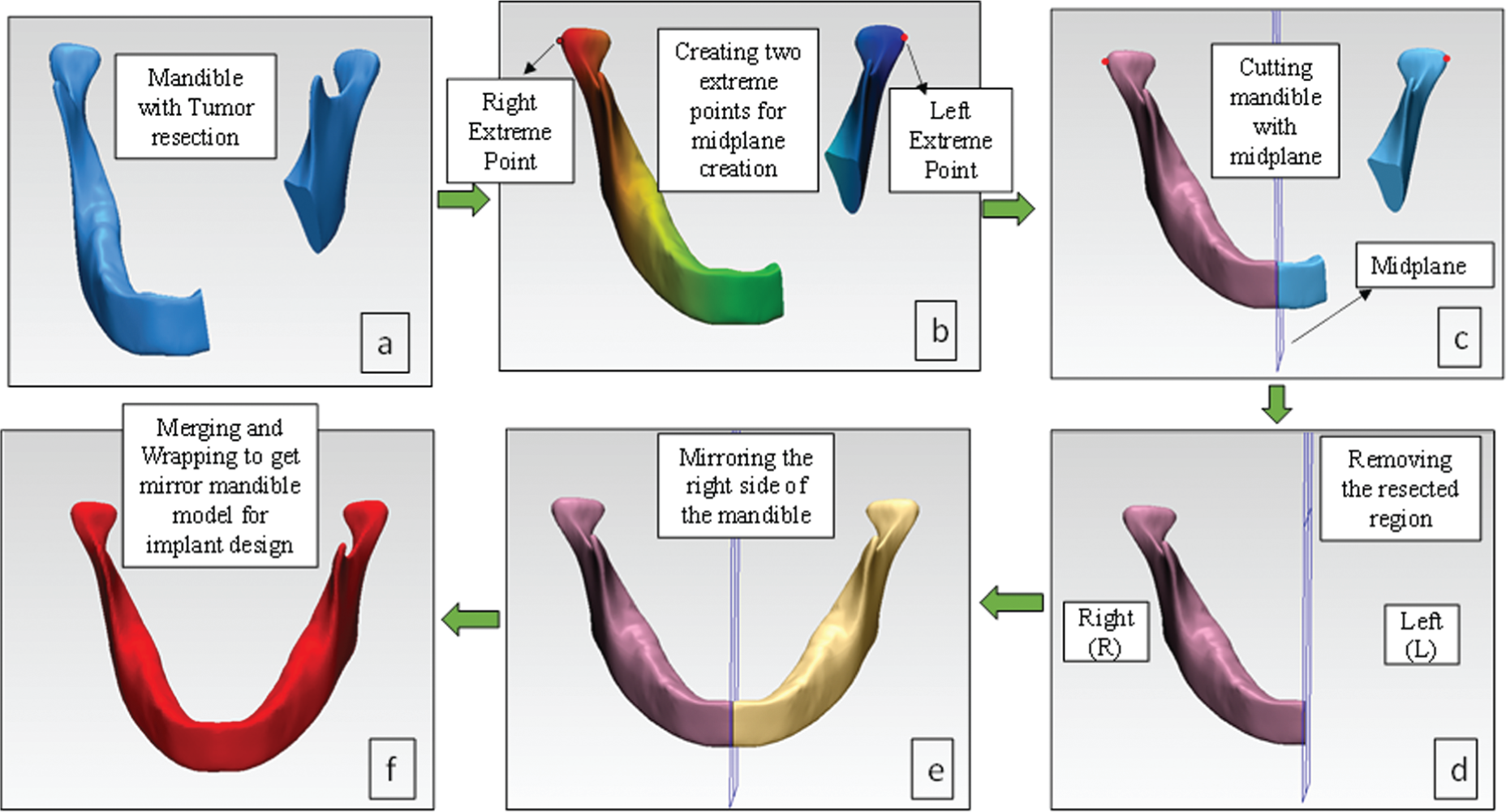
Steps involved in the design of the mandible model to be utilized for implant generation using 3-Matic. (a) Tumor resected mandible part, (b) midplane creation using right and left extreme points, (c) cutting mandible with midplane, (d) resecting the tumor region, (e) mirroring the right side of the mandible, and (f) merging and wrapping operation.
The customized straight plate implant is designed from the mirror mandible model by trimming the left mandible region for the implant design using 3-matic software as presented in Figure 4(b). The outer layer of the trimmed bone is separated, creating a new curve with attach, attract, and split surface options in 3-matic as illustrated in Figure 4(c). An external offset of thickness 2 mm parameter is given to get the thick implant model as shown in Figure 4(d). The final customized straight reconstruction plate is designed from the thick 2 mm model as presented in Figure 4(e).

Customized implant design process: (a) mandible model (from Figure 3(f)), (b) trimmed left mandible region incorporating the tumor region (Figure 2(b)), (c) extracted outer bone layer from trimmed region, (d) offset 2-mm-thick plate model, and (e) customized straight reconstruction plate.
Similarly, the customized sinewave pattern implant is designed following the same procedure as presented in Figure 4. Both plates are made of 2-mm-thick with 2.5-mm-diameter holes for screws. The customized designed reconstruction plate fits perfectly onto the tumor resected region as it is made from the mirror image of the bone itself, unlike the traditional mandible plates where manual bending and machining operations are required for implant fitting.
The main difference between the two design plates is the geometry; both are customized reconstruction plates, one with sinewave pattern plate and the other straight plate. Both plates extend from the mandible symphesis region and connect to the angular region, replacing the tumor on the mandible body region as shown in Figures 5 and 6(a), respectively

Customized sinewave reconstruction plate with six screws, assembly generated in 3-matic.

(a) Mandible framework assembly with straight reconstruction plate; (b) interface of reconstruction plate, screws, and bones; and (c) close-up view of the cortical and cancellous bone, straight plate, and screw.
Mandible model assembly
The mandible design assembly consists of reconstruction plate attached to the mandible framework comprising cortical and cancellous bone with screws. The detailed assembled diagram of sinewave reconstruction plate with three condyle and three chin screws along with mandible framework is illustrated in Figure 5 and straight plate in Figure 6(a).
The screw hole slots in reconstruction plates are tapered such that the screw heads completely sunk inside the plate holes as shown in Figure 6(b) and (c), which helps in enhancing the patient comfort during implant service. The screws used to fix the reconstruction plate are bicortical screws and are engaged in both the outer and inner cortices of the mandible to provide maximum stability and rigid fixation.
FE analysis
To perform the FE analysis of the mandible framework, ANSYS Workbench 14 was used to evaluate the biomechanical response of both the design implants. In order to be closer to the real conditions, 3D FE modeling approach is used in this study. The FE modeling procedure is discussed below.
Materials
In relation to the material properties, the cortical and cancellous bone is taken as homogeneous and isotropic with different properties, whereas some studies used the same material properties for both the bones,16,17 which is not appropriate. This is due to the fact that both the bones are significantly different in strength. The elastic properties of cortical and cancellous bone were determined as per the literature. 18 The material selected for the reconstruction plates is Ti–6Al–4V ELI based upon its high specific strength, biocompatibility, and corrosion resistance. The material properties employed in the FE model are listed in Table 1.
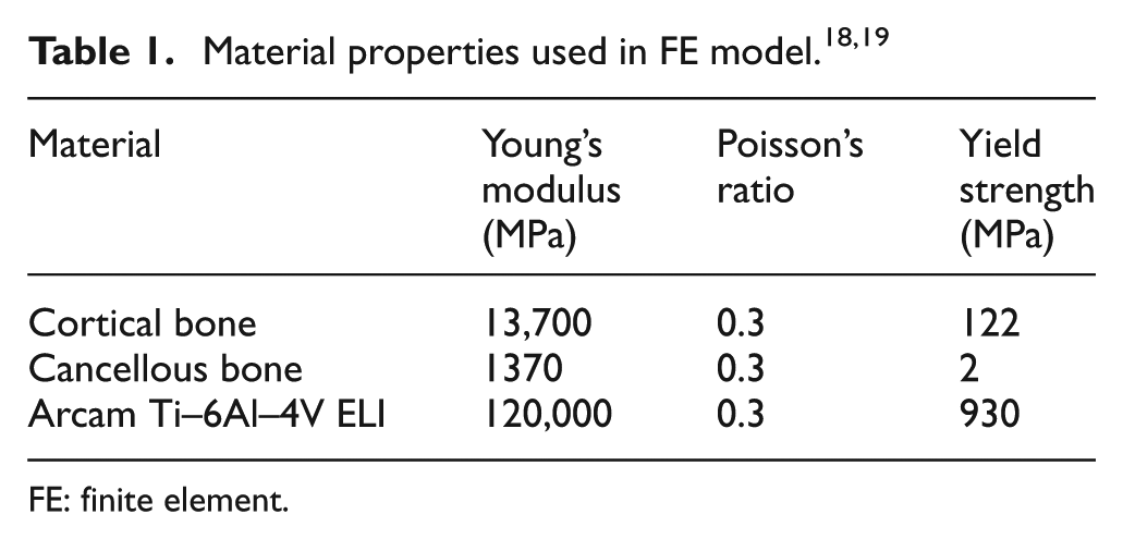
FE: finite element.
Meshing
The mandibular model with reconstruction plate designs is retrieved in ANSYS as an IGES file generated from materialize 3-matic software. Keeping in view of the complexity of the mandibular framework, the 10-node 3D tetrahedral elements were employed. 20 Before selecting a mesh size for the model, a mesh sensitivity study was carried out to reassure that the employed mesh element size is neither time-consuming nor leading to any discretization errors. Convergence study is conducted on five mesh sizes to obtain an estimate of the variation in the von Mises stresses and deformations if any. During meshing, the triangle surface mesher was employed with program-controlled patch conforming method, that is, the mesh size was automatically transitioned in the regions where the geometry dimensions are less than the selected mesh size (screw threads, etc.). 21 Figure 7 shows the results of the mesh convergence study for maximum von Mises stresses and deformations generated in the left condyle region of the sinewave reconstruction plate for five different element sizes. It can be seen from Figure 7 that the von Mises stresses and deformations are almost similar for the range of the five mesh sizes. In the remaining study, the presented results are based on the mesh size 0.4 mm.
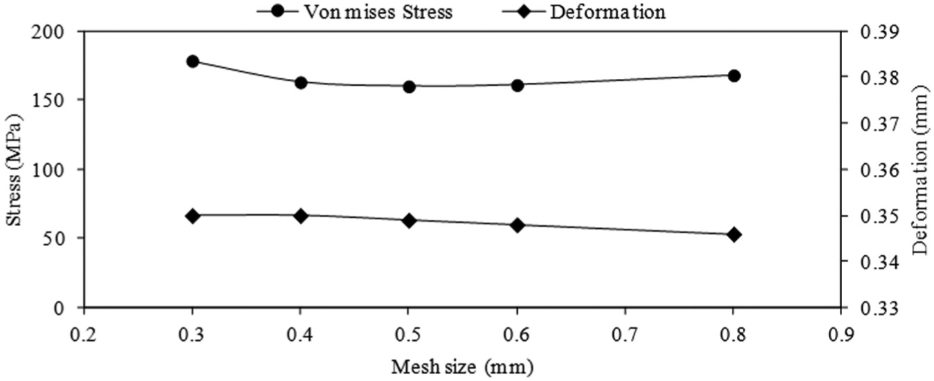
Mesh convergence study on von Mises stress and deformation for five mesh size elements.
In order to generate a good quality mesh, the continuous complex geometry of the mandible framework is first divided into various small free-form patches using 3-matic software. These patches are defined in such a way that the mandible framework is divided into various muscular regions (masseter, temporalis, etc.) which later helps us in defining the load and boundary conditions effectively on a particular location as shown in Figure 8.

Typical loading and boundary conditions on straight reconstruction plate.
Loading and contact boundary conditions
Three main muscular forces masseter, medial pterygoid, and temporalis are used to describe the load on the mandible during chewing operation. The interface between all the materials is defined by using the “bonded” contact type in ANSYS. 22 The magnitudes of muscular forces along various directions are presented in Table 2 and are derived from the literature. 23
Magnitude and direction of muscular forces in Newton. 23

Figure 8 shows the mastication process where the three muscles act during occlusion (chewing). Displacement of both the condyles is fixed and the displacement of the molar region is restricted in the upper region subjected to the chewing force on the mandible. Molar movement is restrained to simulate the biting conditions where the molars undergo near-zero displacement with biting force acting axially. This restraint acts only perpendicular to the occlusal plane (Z-direction) and allowing the freedom of displacement in the horizontal plane (X- and Y-directions) as shown in Figure 8. Same boundary conditions are applied on the sinewave reconstruction model.
Results and discussions
The simulations are oriented to assess the impact of loading based on three muscular forces on the mandible frameworks with two different reconstruction plates. The results are presented in the form of stress and strain distributions, higher values considered as more critical. The von Mises stress distributions on mandible framework with sinewave and straight reconstruction plates are shown in Figure 9(a) and 9(b). The results indicate that the maximum von Mises stress in both the reconstruction plates is predicted toward the condyle region which satisfies the maxillofacial conditions that during chewing the loads are transferred from teeth toward the condyle region. The mandible framework with straight reconstruction plate induces higher maximum stress of 267.21 MPa on the second condyle screw which is almost 40% higher when compared to the maximum stress (168.79 MPa) developed in the framework of sinewave reconstruction as presented in Figure 9(c) and 9(d). This is attributed to the fact that the sinewave reconstruction plate provides increased surface area (2299 mm2) over the same length when compared to the area of the straight reconstruction plate (2143 mm2). Moreover, due to increased surface area, the sinewave reconstruction plate will provide better osseointegration of the bone graft. The maximum stresses developed on both the reconstruction plates and screws are significantly lower when compared to the yield strength (800 MPa) of the Ti–6Al–4V ELI. A comparative summary of stimulated results of stress and strain distributions on both plates is presented in Table 3.
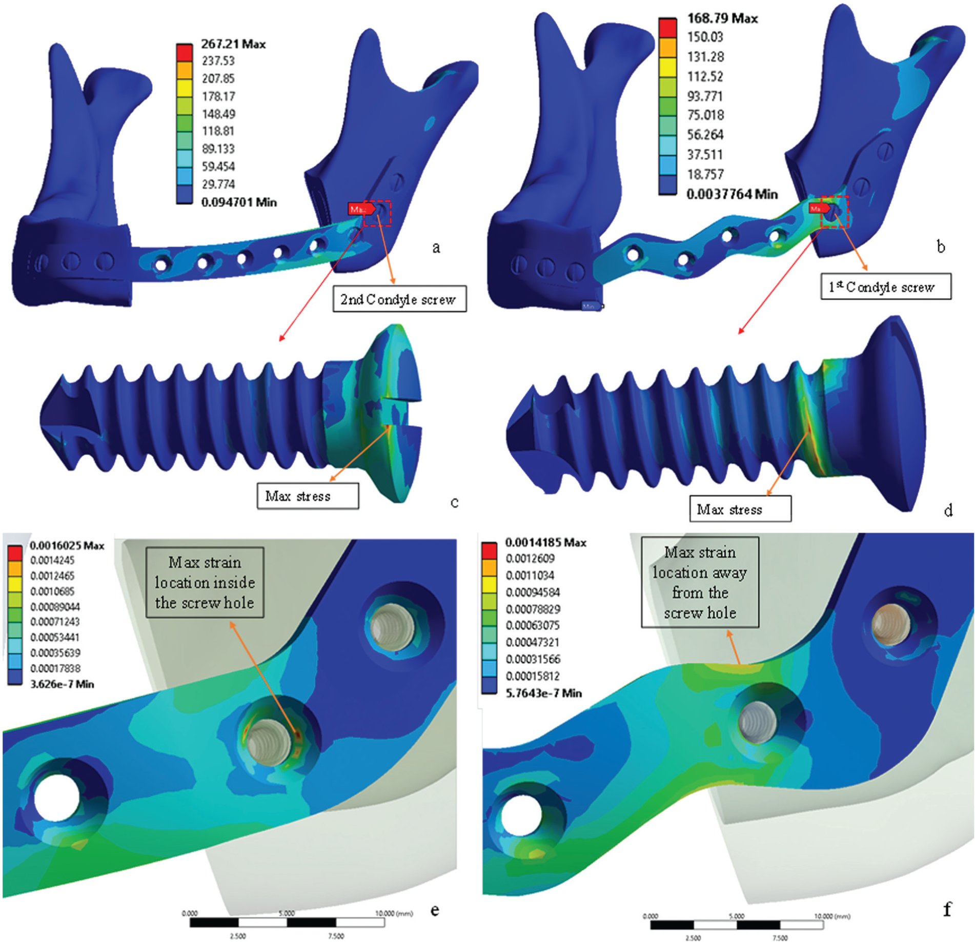
(a) Straight plate with maximum stress acting on second condyle screw, (b) sinewave plate with maximum stress acting on first condyle screw, (c) second condyle screw of straight plate with maximum stress, (d) first condyle screw of the sinewave plate with maximum stress, (e) enlarge view of sinewave plate with maximum strain inside the screw hole, and (f) enlarge view of straight plate with maximum strain away from the screw hole.
Summary of maximum (max) values of stresses and strains in straight and sinewave reconstruction plates.

The other parameter to evaluate the design of both the reconstruction plates is their flexibility, that is, the capability of each plate to absorb the chewing load. The mandible framework is considered to be more stable when the condyle screws and the bone interface remain intact as long as possible. This means the reconstruction plate design which induces lower strains in the screws is considered more flexible. As seen in Figure 9(e), the maximum strain (0.0016) developed inside the first condyle screw hole in the straight plate when compared to the sinewave plate (0.0014). Moreover, the location of the maximum strain in the sinewave plate (Figure 9(f)) is away from the condyle screw holes. This implies that the relatively less load will be transferred; resulting in lower strains developed in the condyle screws in case of sinewave plate, thus providing better flexibility. These results indicate that the chances of loosening of the condyle screws are lower in the sinewave plate due to lower maximum strain developed when compared to straight plate.
Load sensitivity analysis
Each person’s physique and bone structure are different from others which means the chewing load can vary in both magnitude and direction. Food with its distinct structural and mechanical properties elicits different recruitment patterns of muscular forces during chewing.24–27 However, no experimental data could be found in the literature regarding the mandible muscular forces and its magnitude variations in specific direction. Based on these reasons, a load sensitive analysis is performed on both the reconstruction plate designs by varying the loading conditions from the default (literature-based) values 20 up to maximum of 30%. The goal of the load sensitivity analysis is to find which of the two designs are less sensitive to the variations in chewing loads. A stepwise 10% increase in muscle loading conditions in “Y” and “Z” directions is considered, whereas the masticatory forces on the “X” direction are considered fixed as the jaw is intact in that direction. Figure 10 shows the default loading condition for the temporalis region with the angle (θ) showing the total load variation for the temporalis muscles. The loads for the other two muscles (masseter and medial pterygoid) are subjected to similar load variations. Table 4 shows the values of loads for various muscles after 10%, 20%, and 30% variations and corresponding stresses generated in both the plates. The responses of both the plates corresponding to load variations are assessed by calculating the increase in stresses as compared to the stresses developed during the default loading conditions which are expressed as the following equation


Variation in load for temporalis during load sensitive analysis, θ = total range of load variation.
Default load and its variation for various muscles and corresponding changes in stresses.

Figure 11 shows the comparison of percentage increase in the stresses in sinewave and straight reconstruction plates on applying the load variations. The analysis reveals that the straight reconstruction plate is more sensitive to load variations. A 10% increase in muscular forces results in 15%−20% higher increase in percentage stress in straight plate when compared to sinewave plate. This is attributed to the facts of increased surface area of the sinewave reconstruction plate and its better flexibility compared to the straight reconstruction plate.

Comparison of percentage increase in stress for straight and sinewave reconstruction plates.
Conclusion
In this article, a relatively new approach of customized designed implants is implemented for the comparative design study of two reconstruction plates; first, the straight plate designs commonly used and second, the newly proposed sinewave design. The biomechanical behavior of the two mandible reconstruction plate designs is examined on the basis of stability through computation of stresses, strains, and load sensitivity analysis by using FE method.
The most common failure of mandible reconstruction is either the failure of the reconstruction plate (related to stress) or the loosening of the screws (related to strains). The maximum stress induced in the mandible framework with sinewave reconstruction plate (168.79 MPa) is significantly less when compared to straight plate mandible framework (267.21 MPa). However, the stresses in both the plates are within the failure limits of the implant material (Ti–6Al–4V ELI). Furthermore, it is observed that the maximum stresses developed alone are not sufficient to evaluate the design of the reconstruction plates. The load transferring capability (flexibility) of the plates needs to be accessed as well by observing the strain developed for both plate designs. The FE analysis results reveal that the commonly used straight reconstruction plates are more susceptible to loosening of the screws due to higher strains concentrated on the screw hole (14% higher) under same loading conditions when compared to newly designed sinewave reconstruction plate.
The load sensitive analysis results indicate that the straight reconstruction plate is more sensitive to the load variations. A 10% increase in muscular forces elicits approximately 15%−20% stress increase in straight plate as compared to the sinewave plate. These results enhance the understanding of the reconstruction plates in the mandible when considering the design and it can be suggested that sinewave reconstruction plate can significantly improve the stability and safety of the mandible implant. In the future, we aim to evaluate the designs further under dynamic conditions incorporating a more detailed model.
Footnotes
Academic Editor: Farzad Ebrahimi
Declaration of conflicting interests
The authors declare that there is no conflict of interest.
Funding
This project was funded by The National Plan for Science, Technology and Innovation (MARRIFAH), King Abdul-Aziz City for Science and Technology, Kingdom of Saudi Arabia, Award Number (12-INF2685-02).