
Abstract
The impeller of hydraulic turbine is a kind of centripetal impeller. The slip phenomenon within centripetal impeller is different with centrifugal impeller. In this study, the velocity distribution and the flow form of fluid within centripetal impeller are analyzed, the slip factor within centripetal impeller is calculated, and the basic energy equation of hydraulic turbine is deduced when the slip within centripetal impeller is considered. The results of theoretical calculation, the results of experiment, and the results of computational fluid dynamics calculation are compared. The formula of slip factor within centripetal impeller is obtained, and the relative error between the results of theoretical calculation using the formula and experimental data is less than 5%. The effect factors of slip factor have entrance diameter of centripetal impeller, blade numbers, entrance and outlet blade angles, rotating speed of centripetal impeller, and flow rate.
Introduction
It has slip phenomenon in some working machines, for example, pump, fan, and compressor. At present, scholars adopt the method of experiment, theory, and numerical calculation to research slip phenomenon in the working machine, and they put forward a lot of calculation formulas of slip factor about them.1,2 Literature
3
finds that experimental values and theoretical values of the slip factor of centrifugal pump are very close at the design condition, but their difference is bigger at the off-design condition. Therefore, literature
3
also puts forward a calculation formula of slip factor for the centrifugal pump which is fit for the off-design condition. Because the calculation results of slip factor for centrifugal pump are different in different conditions, some scholars also put forward relevant calculation formulas.4–6 In order to further improve the computational precision of slip factor, some scholars amend these formulas.7–10 In addition to the calculation formulas of slip factor which are fit for single-phase fluid, it also has the calculation formula of slip factor which is fit for two-phase flow.
11
It also has slip phenomenon in some prime motors, for example, hydraulic turbine and steam turbine. Their slip values are different for the working machine. The outlet blade angle must be carefully calculated in the working machine; however, in the prime motor, scholars do not accurately calculate outlet blade angle, but only amend it about
In this study, to begin with, we analyzed the flow mechanism of fluid within centripetal impeller and then deduced the calculation formula of slip factor within centripetal impeller of hydraulic turbine when the blade numbers are finite and also deduced the basic energy equation of hydraulic turbine according to the flow mechanism of fluid within centripetal impeller when we considered slip within centripetal impeller; finally, we verified the accuracy of these formulas by the method of experiment and numerical calculations.
Relative velocity within the centripetal impeller under the finite blade numbers
It has a relative axial eddy motion in the centripetal impeller when the blade numbers are finite,13,14 its rotating angular velocity is equal to the rotating angular velocity of impeller, and its direction is opposite to the rotating angular velocity of impeller. It seems like a closed container that is full of liquid, the liquid keeps its original state because of the effect of liquid inertia when the container rotates, and then it causes a relative rotating motion of liquid in the container. 15
In addition to having a relative axial eddy motion in the centripetal impeller, there is a uniform relative flow when the blade numbers are finite. Because the relative velocity is evenly distributed from the pressure surface of blade to the suction surface of blade in the centripetal impeller when the impeller is static. Therefore, the relative motion is the sum of radial uniform flow and relative axial eddy motion in the centripetal impeller of hydraulic turbine.
When centrifugal pump as turbine, there are eddy appears on the pressure surface of blade at the design condition.16–19 This is because there is axial eddy in the centripetal impeller, and when centrifugal pump reversal occurs, positive curvature blade strengthens the velocity gradient of vertical direction of channel. This leads to the emergence of eddy. So the relative velocity within the centripetal impeller gradually decreases from the suction surface of blade to the pressure surface of blade (Figure 1). Because the relative velocity is different on both sides of the blade, there are pressure differences on both sides of the blade; it comes into being the torque on the impeller shaft, and the torque makes impeller rotating.

Distribution of relative velocity in centripetal impeller: (a) infinite blade numbers and (b) finite blade numbers.
Slip factor within centripetal impeller under the finite blade numbers
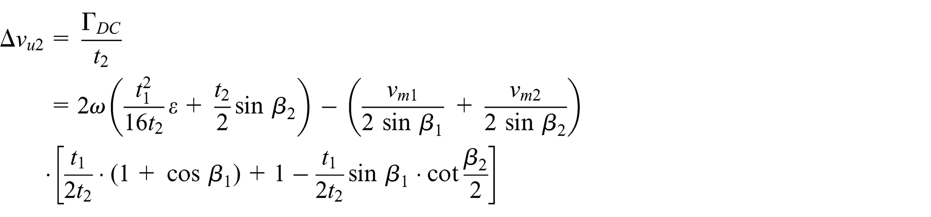
Because of the effect of relative eddy motion, the relative velocity deviates from the tangent direction of blade in the centripetal impeller outlet. The change in velocity triangle is shown (Figure 2). This deviation is due to the effect of fluidic inertia; it makes the flow angle

Velocity triangle of centripetal impeller outlet.
Following velocity triangle, the projection of

Axial eddy.
In order to calculate

where
The intensity of axial eddy is evenly distributed, so velocity circulation

In order to calculate

Approximate figure: (a) approximate triangle and (b) approximate quadrilateral.
We do
In curvilinear triangle

Namely,
Visible, the triangle

In quadrilateral

Therefore, the area of triangle

In the right-angled trapezoid


Because
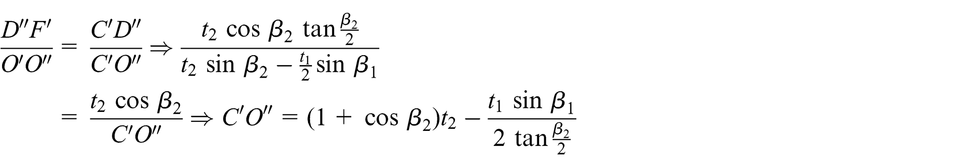
Therefore,

Rearranging the equation

Therefore, the area of quadrilateral
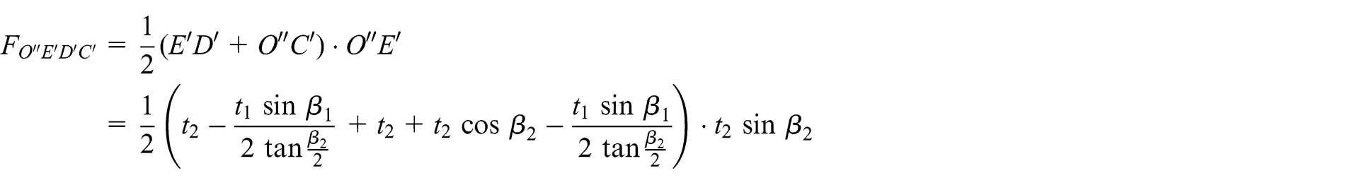
Rearranging the equation
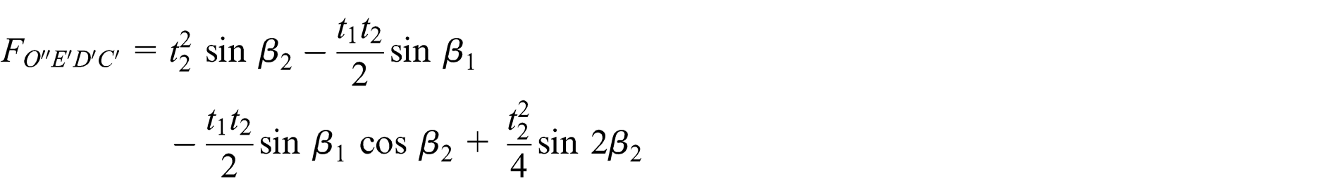
The area of triangle

Rearranging the equation

Therefore,, the area of quadrilateral

Rearranging the equation

Therefore
Rearranging the equation

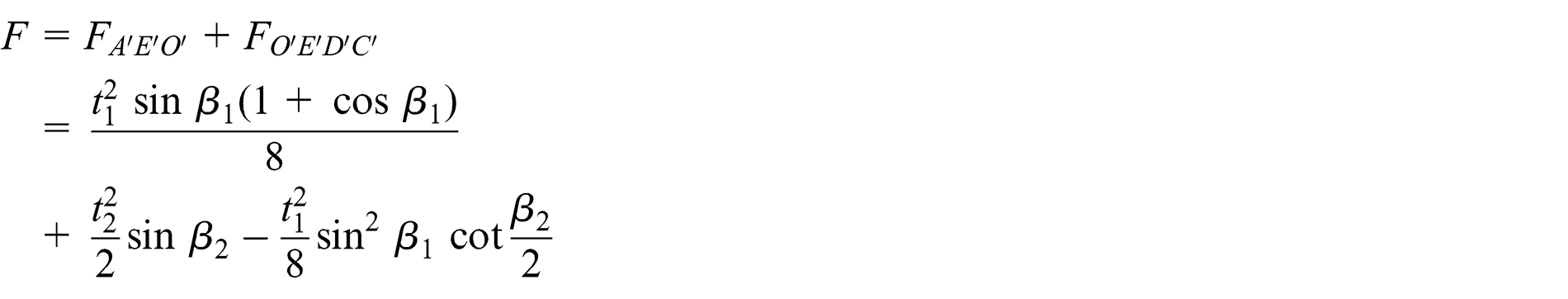
Assuming that

then

Substituting equation (3) into equation (2)


Because the deviation of relative velocity
The average value

And

Therefore, the circulation

From entrance and outlet velocity triangle

Therefore

Namely

So the deviation of circumferential velocity component within centripetal impeller under the finite blade numbers
And

Assuming that slip factor within centripetal impeller is
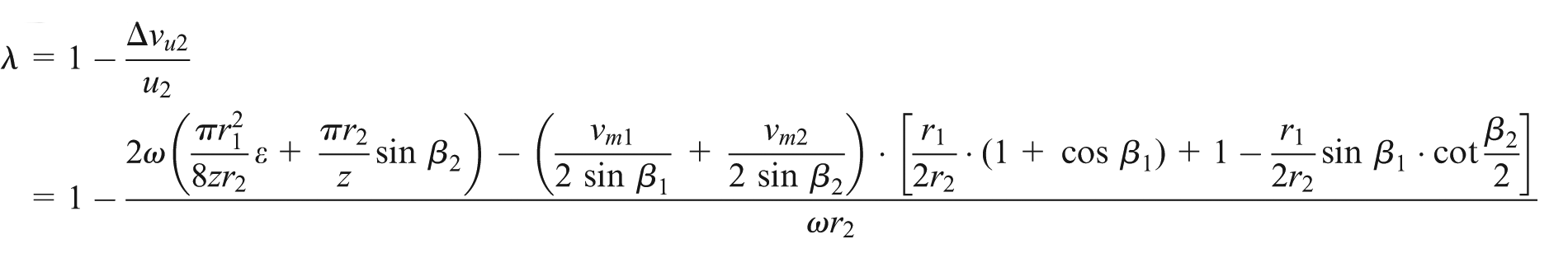
Rearranging the equation

where
Basic energy equation of hydraulic turbine under the finite blade numbers
Following entrance velocity triangle (Figure 5)


Entrance velocity triangle of centripetal impeller.
From outlet velocity triangle
Therefore, slip factor within centripetal impeller

Therefore

Following the basic energy equation, namely, Euler equation
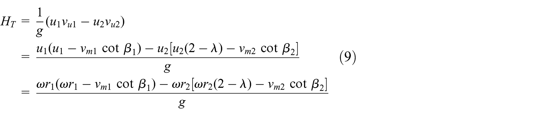
The above equation is theoretical head of hydraulic turbine under the finite blade numbers.
So the hydraulic efficiency of hydraulic turbine

where
Then, the total efficiency of hydraulic turbine

where
Experimental verification
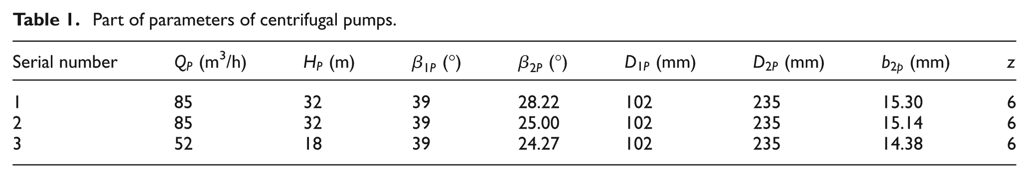
Equation (11) is used to calculate total efficiency of three centrifugal pumps as turbines at the optimum condition. The parameters of these centrifugal pumps are listed in Table 1. The calculation results are compared with the experimental data and numerical calculation results of the literature.20–22 Finally, the results of comparison among theoretical calculation, experimental calculation, and numerical calculation are shown at the optimum condition (Table 2).
Part of parameters of centrifugal pumps.
Comparison among theoretical calculation results, experimental results, and numerical calculation results.

CFD: computational fluid dynamics.
The errors among theoretical calculation results, experimental data, and numerical calculation results are less than 5% at the optimum condition (Table 2). The results of theoretical calculation are bigger than the experimental data. This is because we did not consider mechanical friction loss, the loss is caused by friction between the bearing and mechanical seal, also ignored the leakage loss of balance hole in the theoretical calculation. The results of theoretical calculation are closer than the results of computational fluid dynamics (CFD) calculation of the experimental data. Therefore, formulas (9)–(11) can be used to better predict the performance of hydraulic turbine at the optimum condition.
Effect factors of slip factor of hydraulic turbine
We show from equation (6) that the effect factors of slip factor of hydraulic turbine have entrance and outlet diameters
Effect of flow rate on slip factor of hydraulic turbine
The results of theoretical calculation, experimental measurement, and numerical calculation of model 3 are shown in different flow rates (Table 3).
Calculation results of model 3 in different flow rates.

CFD: computational fluid dynamics.
The error between theoretical calculation and experimental measurement is minimum at the optimum condition. With flow rate deviating from the optimum condition, the error between them gradually increases (Table 3). So equations (9)–(11) cannot be used to accurately calculate the total efficiency of hydraulic turbine at the off-optimum condition. With the increase in flow rate, the slip factor within centripetal impeller is gradually increased, namely, the slip value within centripetal impeller is gradually decreased (Table 3). The main reason is that it generates the eddy on the pressure surface of blade and also generates flow separation on the suction surface of blade when flow rate is less. This leads to the slip value being larger in the centripetal impeller outlet. With the increase in flow rate, the function of restriction of blade gradually strengthens for fluid, and the slip value of centripetal impeller outlet is gradually decreased.
Effect of entrance and outlet diameters of centripetal impeller on slip factor of hydraulic turbine
The change curve of slip factor is shown when the entrance and outlet diameters of centripetal impeller change at the design condition (Figure 6). With the increase in entrance diameter of centripetal impeller, the slip factor of hydraulic turbine is gradually decreased (Figure 6), namely, the slip value within centripetal impeller is gradually increased. The effect of outlet diameter of centripetal impeller on slip factor is less; therefore, the effect of outlet diameter of centripetal impeller on slip factor may be not considered when we research slip within centripetal impeller of hydraulic turbine.

Effect of (a) entrance diameter and (b) outlet diameter on slip factor.
Effect of entrance and outlet blade angles on slip factor of hydraulic turbine
The change curve of slip factor is shown when the entrance and outlet blade angles change at the design condition (Figure 7).

Effect of (a) entrance blade angle and (b) outlet blade angle on slip factor.
With the increase in the entrance blade angle, the slip factor within centripetal impeller first decreases and then increases (Figure 7). So the slip value within centripetal impeller first increases and then decreases. With the increase in the outlet blade angle, the slip factor within centripetal impeller is gradually decreased, namely, the slip value within centripetal impeller is gradually increased. Therefore, in order to reduce the slip value within centripetal impeller, we should take larger or smaller entrance blade angle and smaller outlet blade angle.
Effect of blade numbers on slip factor of hydraulic turbine
The change curve of slip factor is shown when the blade numbers change at the design condition (Figure 8). With the increase in blade numbers, the slip factor within centripetal impeller is gradually increased, and the rate of increase is gradually decreased (Figure 8). Therefore, with the increase in blade numbers, the slip value within centripetal impeller is gradually decreased. The main reason is that function of restriction of blade gradually strengthens for fluid with the increase in blade numbers; it leads to the slip value within centripetal impeller being gradually decreased.

Effect of blade numbers on slip factor.
Effect of entrance width of centripetal impeller on slip factor of hydraulic turbine
The results of comparison between theoretical calculation and CFD calculation are shown under the different entrance widths of centripetal impeller (Table 4). The effects of entrance width on slip factor and head of hydraulic turbine are less (Table 4); therefore, the effect of entrance width of centripetal impeller on slip factor may be not considered when we research slip within centripetal impeller of hydraulic turbine.
Calculation results under the different entrance widths of centripetal impeller.
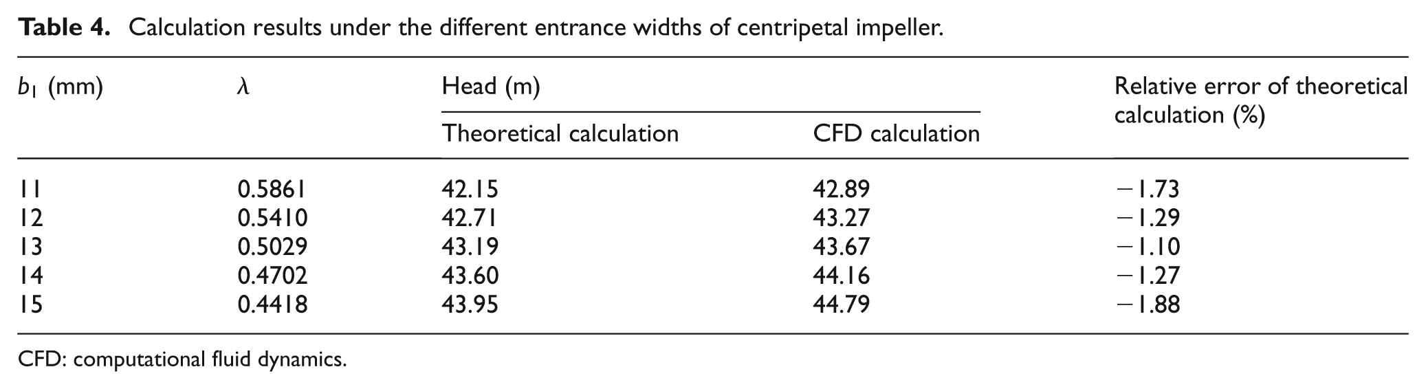
CFD: computational fluid dynamics.
Conclusion
In this article, we obtained the calculation formula of slip factor within centripetal impeller of hydraulic turbine and also obtained the basic energy equation of hydraulic turbine when we considered slip within centripetal impeller under the finite blade numbers. These formulas have higher precision than numerical calculation when we predicted the performance of hydraulic turbine at the optimum condition.
When the blade numbers are finite, the relative motion is the sum of radial uniform flow and axial eddy motion in the centripetal impeller of hydraulic turbine. The rotating angular velocity of the axial eddy is equal to the rotating angular velocity of centripetal impeller and its direction is opposite to the rotating angular velocity of centripetal impeller. The relative velocity within centripetal impeller gradually decreases from the suction surface of blade to the pressure surface of blade.
The effect factors of slip factor of hydraulic turbine have entrance diameter of centripetal impeller, blade numbers, entrance and outlet blade angles, flow rate, and rotating speed of centripetal impeller. With the increase in blade numbers and flow rate, the slip value within centripetal impeller is gradually decreased. With the increase in entrance diameter of centripetal impeller and outlet blade angle, the slip value within centripetal impeller is gradually increased. With the increase in entrance blade angle, the slip value within centripetal impeller first increases and then decreases.
Footnotes
Appendix 1
Academic Editor: Fakher Chaari
Declaration of conflicting interests
The author declares that there is no conflict of interests regarding the publication of this article.
Funding
This work was supported by grants from the Nature Science Foundation of China (51279172) and “the 12th Five-Year Plan” Nature Science and Technology Support Plan Foundation of China (2012BAA08B05).