For an oscillating system, large amplitude indicates strong vibration energy. In this article, modal interaction is used as a useful means to regulate strong nonlinear vibration energy of the flexible arm undergoing rigid motion. A method is put forward to migrate and dissipate vibration energy based on modal interaction. By means of multiple-scale perturbation analysis, it is proven that internal resonance can be successfully established between modes of the flexible arm and the vibration absorber. Through examples and analyses, it is verified that this control method is effective in regulating strong vibration energy and can be used to suppress strong nonlinear vibration of the flexible arm undergoing rigid motion.
Due to larger work space, better energy efficiency, and higher speed, flexible arms are most likely to constitute new generation of robotic manipulators in space exploration. However, the vibration problem remains a large obstacle to overcome. Any disturbances may result in deteriorative tracking accuracy and serious control issues.
To combat this drawback, various methods have been put forward, from enhancing stiffness, increasing damping, optimizing shape, to experimenting new materials.1–4 In recent years, a large number of active control methods are suggested,5–7 and many of them are implemented based on smart materials, like piezoelectric ceramic and shape memory alloy.8,9 Notwithstanding, they perhaps encounter difficulties in diminishing nonlinear vibration with strong energy. On one hand, strong energy may excite large amplitude, and thus, many nonlinear terms become significant and must be taken into account. Therefore, a variety of vibration control strategies making use of a linear model or a linearized model will result in fundamental mistakes. On the other hand, since active control methods suppress vibration with the help of external energy, they are not always effective to suppress strong vibration due to limited energy output of smart material actuators. In the worst case, these actuators will suffer from dangerous overload damages.10
In fact, although nonlinearities bring about analytical difficulty, modal interaction caused by them potentially provides new solutions to regulating nonlinear vibration. Nayfeh11 found that vibration energy of one mode can be transferred via internal resonance to another mode which is commensurable or nearly commensurable with the former. Golnaraghi,12 Tuer et al.,13 and Oueini and Golnaraghi14 used internal resonance to decrease the structural vibration of a flexible cantilever beam. However, the flexible cantilever beam they had researched was assumed as a rigid beam connected by a torsional spring. Obviously, this simplified model is not feasible to the long and thin flexible arm that should be represented by a distributed model. In recent years, the above studies have been extended to control vibration of the distributed flexible beam.15–18 But these studies only dealt with the flexible beam without rigid motion and did not involve the flexible arm undergoing large-scale joint motion. Actually, the latter exhibits much more complex dynamic behaviors.
To the best of our knowledge, there is little research on reducing nonlinear vibration of the flexible arm via internal resonance. Whether internal resonance can be successfully established for the flexible arm with joint motion should be proved and verified. In this study, a vibration absorber is attached to the flexible arm to introduce quadratic nonlinearity into the system, thereby generating desired nonlinear coupling with the controlled mode of the arm. By means of multiple-scale perturbation analysis, it is proven that internal resonance can be established. Different from actively suppressing vibration via external energy, using this method, strong nonlinear vibration energy of the flexible arm can be effectively migrated and dissipated by the vibration absorber.
Mathematical model
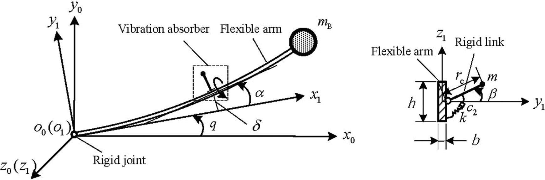
To test the effectiveness of the proposed method, a model consisting of a flexible link, a rigid joint, and a vibration absorber is studied, as shown in Figure 1. denotes the global coordinate system and denotes the moving coordinate system defined on the flexible arm. The flexible link rotates round the rigid joint with rotational angle q in the plane . The flexible link has length l with uniform mass density per unit length ρ. The cross section of the link is rectangle with height h and width b. A payload is attached at the endpoint of the link with mass . Only the deflection δ of the link about y1 axis is considered. The vibration absorber, connected to the flexible arm at , is made up of a weightless rigid link with a mass , a torsional spring with the stiffness , and a damper with the damping . The swing angle of the rigid link is denoted by β. It should be noted that, with a passive configuration, the values of stiffness and damping of the vibration absorber are fixed, whereas in a semi-active form, the values of stiffness and damping can be regulated by adjustable position and velocity feedback.
Mathematical model.
According to the assumed-mode theory, the deflection δ of the flexible link consists of multiple modes. Considering the deformation is mostly contributed by the fundamental mode, only the fundamental mode of the flexible link is investigated. We have
where and are the fundamental modal coordinate and mode shape of the flexible link, respectively. The angle of the tangent of the flexible link at with respect to -axis is denoted by , . The axial displacement resulting from the transverse bending of the link can be written as
where is a dummy variable and .
Using Kane’s method, the flexible dynamic equations about and are derived
where ; rc is the length of the rigid link. ; ; ; ; ; ; ; ; ; ; ; ; ; is the stiffness of the torsional spring; ; and are the damping of the flexible link and the damper, respectively; is the flexural rigidity of the flexible arm; is the moment of inertia of the tip mass of the rigid link.
Perturbation analysis
Equations (3) and (4) must be nondimensionalized to facilitate the scaling required by the perturbation analysis. Here, the nondimensional quantities are defined as , , , and , where . The nondimensional dynamic equations are
where ; ; ; ; ; ; ; ; ; ; ; .
To make the damping and nonlinearities appear in the same perturbation equations, let , , , , and , where ε is a small nondimensional bookkeeping parameter, . Then, equations (5) and (6) can be expressed as
According to the method of multiple scales, φ, ψ, and T are expanded in power series with ε and take the form
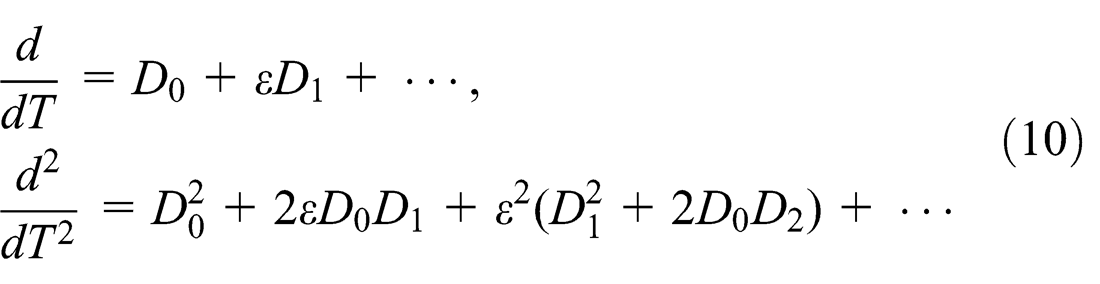
It follows that the derivatives with respect to T become expansions in terms of the partial derivatives with respect to Ti according to
where (i = 0, 1, …).
Substituting equations (9) and (10) into equations (7) and (8), expanding, and equating the coefficients of and to 0, we have
where and are functions of slow time , and denotes the complex conjugate of the preceding term. Substituting equation (14) into equations (12) and (13) leads to
where .
In this study, the absorber is used to control the vibration of the flexible link at the 2:1 internal resonance condition, that is, . To express the nearness of the frequency to twice , a detuning parameter σ is defined as . Then, we have , .
Equating the coefficients of and on both sides of equations (15) and (16) yields
and can be expressed in their polar forms as
where , , , and are the real functions of the slow time ; and are defined as the modal amplitudes.
Substituting equation (19) into equations (17) and (18) and then separating the result into real and imaginary parts, we obtain
Thus, the problem is reduced to the solution of equations (20), (21), and (24).
In order to better understand the energy transfer between the flexible arm and the vibration absorber, the undamped case (i.e. ) is studied first. Equations (20) and (21) can be written as
Multiplying by and by , where , adding the resulting equations, and integrating yield
where is a constant proportional to the initial energy of the system.
From , it is clear that , and thus, and in equation (26) are always bounded. That is to say, the system is conservative and the energy remains constant when the damping is ignored. Therefore, if the modal amplitude is periodic, then the modal amplitude will be periodic and out of phase with . Equation (26) indicates that, in the absence of damping, the energy in the system is continuously exchanged between the fundamental mode of the flexible arm and the vibration mode of the absorber.
In the presence of damping (i.e. and ), for steady-state solutions, , then we have
By inspection, it is determined that the system possesses an infinite number of equilibrium points defined by , , and . The Jacobian matrix is constructed to determine the stability of the fixed points , , and
By evaluating the eigenvalues of the Jacobian matrix, stability is determined. Eigenvalues should not have positive real parts to maintain stability. Obviously, the corresponding eigenvalues are , and and . So the modal amplitudes and are stable. The phase is unstable due to zero eigenvalue. However, unstable phase merely governs the modulation between the modal amplitudes and has no effect on the magnitude of the modes. It cannot influence stability of the mode vibration and thus is of no concern.
Examples and analyses
To verify the above analysis, a one-link flexible arm is used in the following example, as shown in Figure 1. The flexible link is a uniform Euler–Bernoulli beam with the length , the rectangle cross section of height , width , and a tip mass . The link is made of aluminum with elastic modulus 71 GPa and mass density 2710 kg/m3; only the in-plane flexural deformation about the -axis is considered.
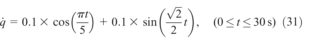
Suppose the joint motion of the arm is
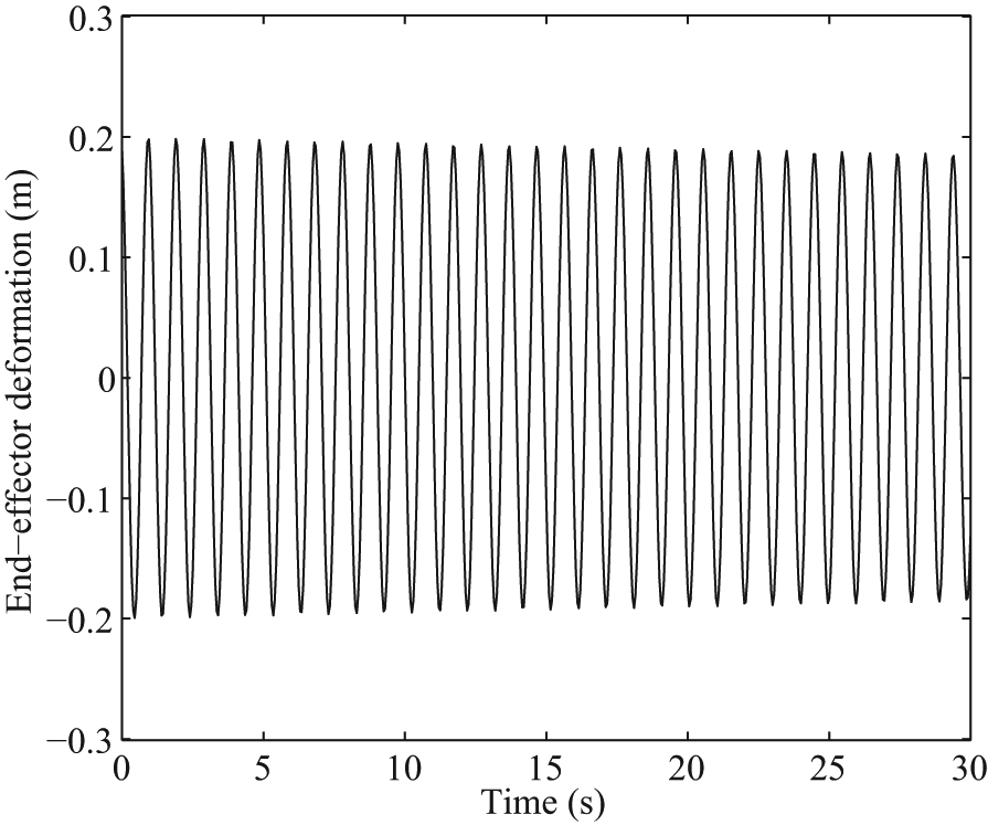
If the flexible arm has no vibration absorber, given the initial large disturbance (large amplitude indicates strong energy), its end-effector deformation is obtained when moving according to equation (31), as shown in Figure 2. Due to the low damping and presence of rigid motion, the end-effector vibration of the flexible arm cannot be decreased by itself. To reduce vibration via internal resonance, a vibration absorber is attached to the flexible link at , with mass and . At the state of 2:1 internal resonance, equations (20)–(24) are integrated numerically in the absence of damping. The relationship between the modal amplitude (solid line) and (dashed line) is shown in Figure 3. It can be seen that the peaks and troughs of the responses are exactly 180° out of phase, indicating there is continuous exchange of the energy between modes of vibration.
Response of the uncontrolled arm.
Undamped modal amplitudes.
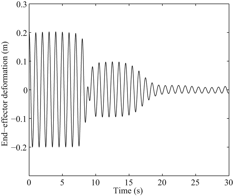
When the damping of the vibration absorber is considered, letting , equations (20)–(24) are integrated numerically at the state of 2:1 internal resonance. The modal amplitudes (solid line) and (dashed line) are illustrated in Figure 4. The coincidence of the peaks of one modal curve with the troughs of the other can be found, demonstrating vibration energy is being transferred between modes. At the same time, the modal amplitudes diminish with time and converge toward the equilibrium value (), verifying that the vibration energy of the flexible arm has been effectively dissipated through modal interaction. The end-effector deformation of the flexible arm is shown in Figure 5. It is decreased remarkably, compared with the uncontrolled case (as shown in Figure 2). The final residual vibration is 0.01 m.
Damped modal amplitudes.
Response of the controlled arm.
In addition, when a vibration absorber is connected to a flexible arm, several parameters are also introduced, including tip mass of the rigid link (), damping of the vibration absorber (), length of the rigid link (), and position of the rigid link (), as shown in Figure 1. These parameters will affect vibration response of the flexible arm. Therefore, it is important to seek optimal values to achieve better results. In this example, the aim is chosen to reduce the vibration response quickly. Therefore, the optimization objective and constraints are
where is the attenuation time when the vibration response is decreased to a certain threshold (e.g. decreasing 90% in this simulation), small means quick reduction; and are the lower and upper permitted tip mass of the rigid link, respectively; and are the lower and upper permitted damping of the vibration absorber, respectively; and are the lower and upper permitted length of the rigid link, respectively; and are the lower and upper permitted position of the rigid link, respectively.
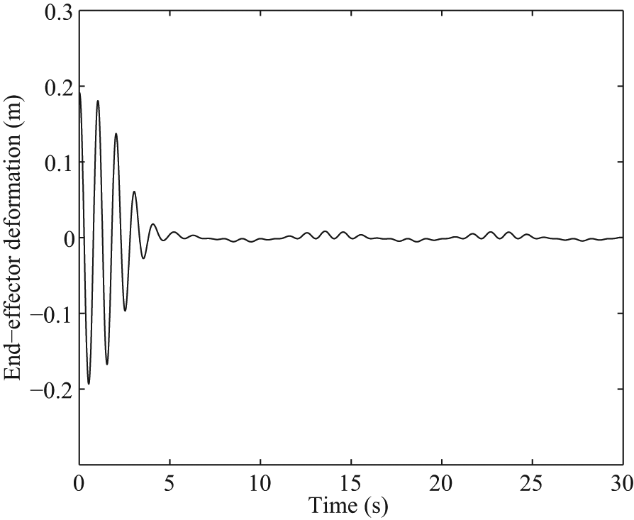
A particle swarm optimization algorithm is designed to obtain the optimal parameters. Several important parameter values are chosen as follows: , , , and . The same parameters as the aforementioned case are used and the corresponding optimization results are obtained, that is, , , , and . In this case, as shown in Figure 6, the end-effector deformation is decreased by 90% within 5 s and the residual vibration is about 0.008 m. Compared with the no optimization case (as shown in Figure 5), the attenuation time is decreased remarkably. It is verified that this control method can reduce nonlinear vibration of the flexible arm more quickly with optimality parameters. Of course, other optimization objectives and constraints can also be chosen.
Optimal response of the controlled arm.
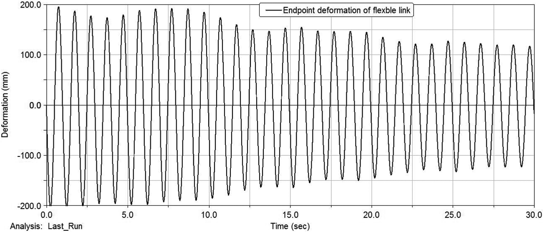
Furthermore, to validate the proposed method, several virtual prototype experiments are conducted using ANSYS software and ADAMS software. A flexible arm with the same parameters as the aforementioned example is used in these simulations, as shown in Figure 7. When the arm is not equipped with a vibration absorber, the corresponding endpoint vibration is shown in Figure 8, where the endpoint deformation decreases slowly.
Simulation model in ADAMS.
Endpoint vibration without a vibration absorber.
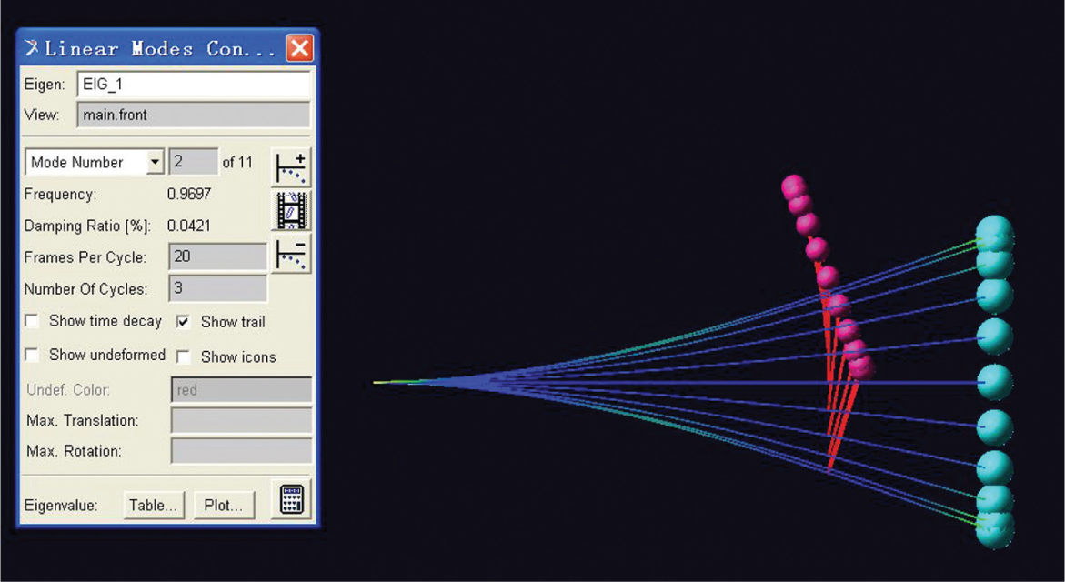
In order to verify internal resonance, the proposed vibration absorber without the damping is attached to the flexible arm. In this case, the first mode is the vibration mode of the absorber, the frequency of which is 0.4814 Hz (Figure 9), and the second mode is the fundamental mode of the flexible arm, the frequency of which is 0.9697 Hz (Figure 10). The frequency ratio between them is . At the state of 2:1 internal resonance, the relationship between the endpoint deformation of the flexible arm and the displacement of the absorber is shown in Figure 11. As can be seen, the endpoint deformation amplitude gradually decreases and gradually increases and then repeats itself; so does the displacement amplitude of the absorber. In addition, when the endpoint deformation amplitude of the arm is decreasing, the displacement amplitude of the absorber is increasing at the same time, indicating the vibration energy is being transferred from the flexible link to the vibration absorber, and vice versa. This “beat” phenomenon can verify the existence of internal resonance.
Vibration mode of the absorber.
Fundamental mode of the flexible arm.
“Beat” phenomenon.
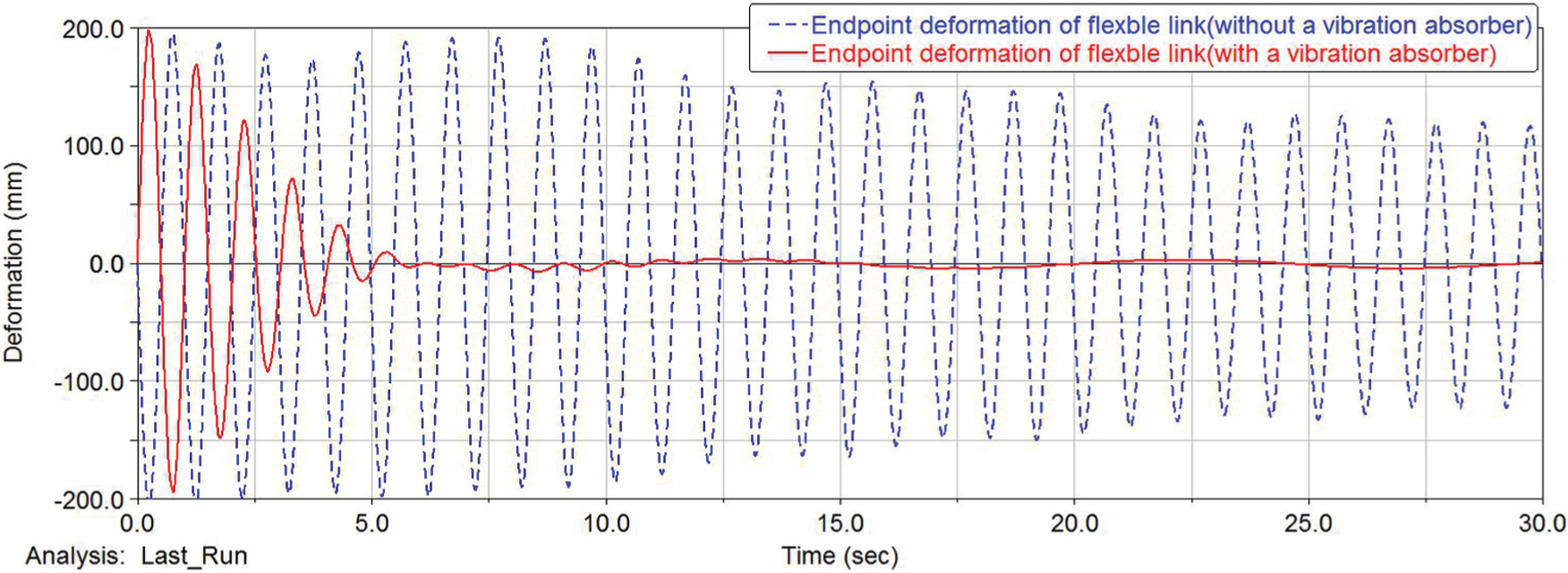
In the presence of the damping of the vibration absorber, the endpoint deformation of the flexible link at the state of internal resonance is shown in Figure 12. For the convenience of comparison, the endpoint deformation without the vibration absorber (as shown in Figure 8) is also listed in Figure 12. It can be seen that the endpoint deformation of the flexible link has been effectively reduced based on internal resonance.
Comparison of the endpoint deformation
Through the above examples, it is verified that this control method based on modal interaction is effective in regulating strong nonlinear vibration energy of the flexible arm undergoing rigid motion.
Conclusion
In this article, modal interaction is used as a useful means to regulate strong nonlinear vibration energy of the flexible arm undergoing rigid motion. A method is put forward to transfer and dissipate vibration energy based on internal resonance. By means of multiple-scale perturbation analysis, it is proven that internal resonance can be successfully established between modes of the flexible arm and the vibration absorber. Through examples and analyses, the effectiveness of this control method is verified. Although a single link model is used for decreasing computational complexity, this method can be extended to a multilink model.
Footnotes
Academic Editor: Yong Chen
Declaration of conflicting interests
The authors declare that there is no conflict of interest.
Funding
This study was supported by the Equipment Pre-Research Foundation of GEH PLA China (No. 9140A340 30315KG18002) and the Major State Basic Research Development Program of China (973 Program) (No. 2013CB733000).
References
1.
CuiLLXiaoZQ. Optimum structure design of flexible manipulators based on GA. In: Proceedings of the IEEE international conference on intelligent transportation systems, Shanghai, China, 12–15 October 2003, pp.1622–1626. New York: IEEE.
2.
DixitUSKumarRDwivedySK. Shape optimization of flexible robot manipulators. J Mech Des Trans ASME2006; 128: 559–565.
3.
GhazaviAGordaninejaddFChalhoubNG. Dynamic analysis of a composite-material flexible robot arm. Comput Struct1993; 49: 315–327.
4.
GordaninejaddFChalhoubNGGhazaviA. Nonlinear deformation of a shear-deformable laminated composite-material flexible robot arm. J Mech Des1992; 114: 96–102.
5.
DwivedySKEberhardP. Dynamic analysis of flexible manipulators, a literature review. Mech Mach Theor2006; 41: 749–777.
6.
BenosmanMLe VeyG. Control of flexible manipulators: a survey. Robotica2004; 22: 533–545.
7.
YunYLiY. Modeling and control analysis of a 3-PUPU dual compliant parallel manipulator for micro positioning and active vibration isolation. J Dyn Syst Trans ASME2012; 134: 021001-1–021001-9.
8.
DadfarniaMJaliliNXianB. A Lyapunov-based piezoelectric controller for flexible cartesian robot manipulators. J Dyn Syst Trans ASME2004; 126: 347–358.
9.
DhanalakshmiKAvinashAUmapathyM. Experimental study on vibration control of shape memory alloy actuated flexible beam. Int J Smart Sens Intell Syst2010; 3: 156–175.
10.
ChenLHansenCH. Nonlinear control of a parametrically excited system subject to actuator saturation. IEEE Decis Contr P2003; 4: 3846–3851.
11.
NayfehAH. Nonlinear interactions. New York: Wiley Interscience, 2000.
12.
GolnaraghiMF. Regulation of flexible structures via nonlinear coupling. Dynam Contr1991; 1: 405–428.
13.
TuerKLGolnaraghiMFWangD. Development of a generalised active vibration suppression strategy for a cantilever beam using internal resonance. Nonlinear Dynam1994; 5: 131–151.
14.
OueiniSSGolnaraghiMF. Experimental implementation of the internal resonance control strategy. J Sound Vib1996; 191: 377–396.
15.
Frank PaiPRommelBSchulzMJ. Non-linear vibration absorbers using higher order internal resonances. J Sound Vib2000; 234: 799–817.
16.
AshourONNayfehAH. Adaptive control of flexible structures using a nonlinear vibration absorber. Nonlinear Dynam2002; 28: 309–322.
17.
YamanMSenS. Determining the effect of detuning parameters on the absorption region for a coupled nonlinear system of varying orientation. J Sound Vib2007; 300: 330–344.
18.
HuiCKLeeYYNgCF. Use of internally resonant energy transfer from the symmetrical to anti-symmetrical modes of a curved beam isolator for enhancing the isolation performance and reducing the source mass translation vibration: theory and experiment. Mech Syst Signal Process2011; 25: 1248–1259.