
Abstract
An average passenger car engine effectively uses about one-third of the fuel combustion energy, while the two-thirds are wasted through exhaust gases and engine cooling. It is of great interest to automotive industry to recover some of this wasted energy, thus increasing the engine efficiency and lowering fuel consumption and contamination. Waste heat recovery for internal combustion engine exhaust gases using Brayton cycle machine was investigated. The principle problems of application of such a system in a passenger car were considered: compressor and expander machine selection, machine size for packaging under the hood, efficiency of the cycle, and improvement of engine efficiency. Important parameters of machines design have been determined and analyzed. An average 2-L turbocharged gasoline engine’s New European Driving Cycle points were taken as inlet points for waste heat recovery system. It is theoretically estimated that the recuperated power of 1515 W can be achieved along with 5.7% improvement in engine efficiency, at the point where engine power is 26550 W.
Introduction
In recent years, car manufactures have been put to a big challenge to further reduce the CO2 emission from vehicles. Along with hybridization, improving efficiency and lowering fuel consumption from vehicles equipped with internal combustion engine (ICE) is the main way to achieve it. Since the early beginnings of ICE, constructors have been aware that a big portion of energy is wasted by throwing high enthalpy exhaust gases to atmosphere. Around 35% of energy produced by fuel combustion is wasted through exhaust gases. This is the case when engine works with good efficiency, at low load efficiency it is even worse, and more energy gets lost with exhaust gases.
There are various technologies for exhaust gases waste heat recovery (WHR). 1 Probably, the most investigated technology is the Rankine cycle. Various studies and experimental installations have been done for both light- and heavy-duty engines. Bredel et al. 2 describe several Voith systems for locomotive, stationary, and marine application. However, for passenger cars, there is no system on the market, but various manufacturers like BMW3,4 and Renault 5 are investigating it. Typically, the maximum increase in the engine efficiency with this system is around 6%. A big challenge for Rankine cycle application is packaging of expander and heat exchangers (HEs) that need to be big to achieve good efficiency. The other cycle that showed potential, but is much less investigated, is a Brayton cycle with air. A Toyota patent 6 proposes the accumulator to store the compressed gas when the heat receiving capacity of gas is small or exhaust gas temperature is low. Song et al. 7 investigate the application of Brayton cycle on a heavy-duty diesel engine using one compressor to feed both the engine and Brayton cycle. The maximum fuel consumption improvement they obtained was 4.6% al low engine speed and full load.
This study focused on the application of Brayton cycle WHR for passenger cars and gasoline engine because of higher exhaust gas temperature. Thermodynamic analysis of the ideal Brayton cycle for selected engine points has been done to estimate the theoretical maximum of the system performance. Mass flows obtained from thermodynamical analysis and limitations of machine size have been used as input factors for selection of compressor and expander. Parameters that affect the recuperated power have been determined and their influence was analyzed. For a concrete engine, working conditions from New European Driving Cycle (NEDC) homologation cycle have been selected as a reference engine point and the recuperated power and improvement of engine efficiency were analyzed.
Engine energy levels
In order to recuperate some part of energy of the exhaust gas, it is important to know the amount of the energy available. The energy level of the exhaust gas coming from the ICE is determined by the mass flow rate and temperature. The engine used in this study is a gasoline 2-L turbocharged engine. Engine main characteristics are presented in Table 1.
Engine characteristics.

ICE has a wide operative range. Figure 1 shows the NEDC that represents the vehicle speed as a function of time. The points from the NEDC marked with letters A–G have been selected as reference engine points for further analysis.
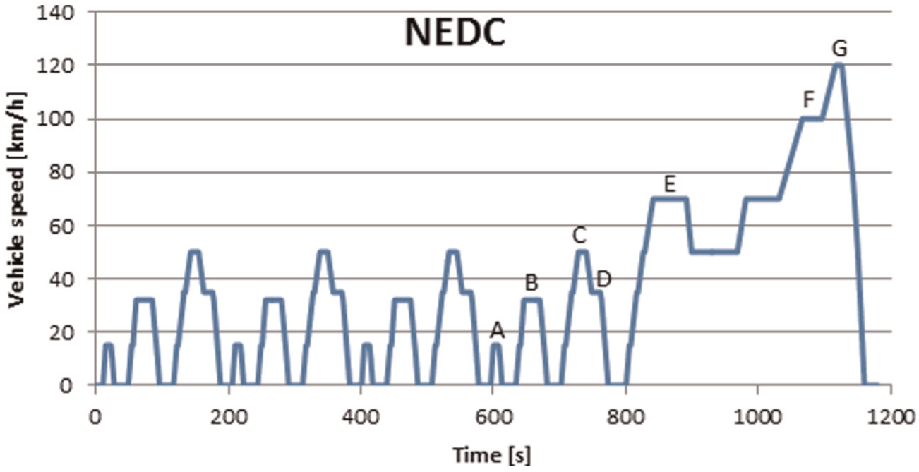
NEDC points.
In Table 2 are given the most important engine values for the selected NEDC points.
NEDC values.

Exhaust gas temperatures from Tables 1 and 2 are the temperatures after the catalyst.
The point G that has the most energy of the exhaust gases was selected for further thermodynamic analysis of the cycle. The possibility of heat recovery from other NEDC points will be analyzed later.
Brayton cycle
Figure 2 represents T-s diagram of the ideal Brayton cycle where the compressor would take the ambient air and compress it isentropically (1–2); then the compressed air would enter the HE where it would receive the heat of the exhaust gas at constant pressure (2–3); the heated compressed air would then be expanded isentropically in the expander machine (3–4); finally, the air would be discharged back to atmosphere and the process would start again.

Brayton cycle T-s diagram.
To simplify the study, it was considered that the exhaust gas is air although in continuation it will be referred to as exhaust gas. The amount of heat that is exchanged in the HE is limited by the temperature difference of two gases. Some authors refer to this temperature difference as pinch point. 8 The selected temperature difference is 10 K.
The temperatures of air and gas in HE depend on mass flows of air and gas. If the mass flow of air is lower than the mass flow of exhaust gas, the pinch point will be between the temperature T3 and the temperature of the gas at the HE inlet Tgas,in. If the mass flow of air is less than the mass flow of the gas, then the pinch point will be between the temperature T2 and exhaust gas temperature at the outlet of HE Tgas,out. This is illustrated in Figure 3.

Pinch point depending on the relation of gases.
By defining the pinch point this way, the amount of heat exchanged will depend on engine point (temperature and mass flow of exhaust gas) and mass flow of air.
Air is considered to be an ideal gas so that enthalpies are functions of temperatures for the corresponding points. Temperature T1 = 288 K is the known temperature at the start of compression. Temperature at the end of compression T2 depends on temperature T1 and pressure ratio p2/p1. The pressure at the start of compression p1 = 1 bar is known while the pressure at the end of compression p2 is a variable. Temperature T3 at the end of heat exchange depends on the pressure at the HE p2 = p3 and the pinch point.
From the definition of pinch point for

For the
Temperature T4 is calculated considering that the pressure p4 = p1 and that the expansion is isentropic from pressure p3.
The cycle is completely defined by defining engine point, pressure at the end of compression p2, and the mass flow of air. As exhaust gas mass flow is fixed for engine point, instead of mass flow of air, the relation of gases can be used
The recuperated power from the cycle is equal to

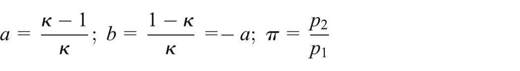
For non-ideal cycle, enthalpies h2 and h4 depend on isentropic efficiency of compressor and expander. For simplicity, it will be assumed that isentropic efficiency of both machines is the same η


where
Substituting equations (3) and (4) in equation (2)

Expressing h3 from equation (1) and replacing it in equation (5), we can obtain

Ideal cycle
Considering air to be an ideal gas, unknown properties were calculated using the National Institute of Standards and Technology (NIST) database. 9 For the engine point G, the recuperated power as a function of pressure p2 and relation of gases is represented in Figure 4.

Recuperated power as a function of pressure p2 and relation of gases.
To analyze the results of the figure, it is useful to fix one parameter and see how changing the other affects the recuperated power.
Mass flow effect
To analyze the effect of air mass flow on recuperated power, pressure p2 was fixed and with it enthalpy h2 is also fixed. For point 3, the definition of pinch point should again be considered.
For set pressure p2, for any
For
The effect of relation of gases could be observed also on T-s diagram. Figure 5 represents three cycles for fixed pressure p2 = 7 bar, fixed engine point G, and variable relation of gases

T-s diagram for fixed pressure p2 and variable relation of gases.
For cycles with
Another way to look at how temperature T3 and temperature of the gas at HE outlet change by varying air mass flow could be by looking at the temperatures of air and gas along the HE. This is represented in Figure 6 where position 0 represents the inlet of air in the HE (outlet of gas) and position 1 the outlet of air in the HE (inlet of gas).

Temperatures of air and gas at heat exchanger inlet and outlet.
For

Pressure ratio effect
To study the effect of pressure ratio p2/p1, the air mass flow should be fixed. Three cycles with same air mass flow and different pressure ratio are presented in Figure 7.

T-s diagram for fixed air mass flow and variable pressure p2.
The optimal pressure ratio that gives the maximum power is the one that will have the biggest area on T-s diagram. More precise way to find the optimal pressure is to analyze it analytically. For

To obtain

For
As it was shown before, for ideal cycle it can be considered that air mass flow should be equal or higher than exhaust gas mass flow. Fixing the

Power as a function of heat exchanger pressure for NEDC points.
The optimal pressure in the HE changes with the engine point. By choosing the optimal pressure, it is possible to recuperate the power for all engine points.
Machine selection
As shown in Figure 8, theoretically it is possible to recuperate power from all the selected engine points. Mechanical, heat transfer, or charge losses that are not included in the previous calculation could waste a lot of the recuperated power and even generate power losses to the engine. That is why it is more reasonable to consider the waste heat recuperation from the points where the engine has a higher exhaust temperature and mass flow and it is possible to recover a higher amount of wasted energy.
To simplify machine selection process, nominal operative point will be the point G when vehicle speed is constant at 120 km/h and exhaust conditions are good for heat recovery. This corresponds to normal highway driving condition. From the thermodynamic analysis for this point for HE pressure of 7 bar that gives the maximum power and
Compression and expansion parameters for point G.

Compressor selection
The recuperated power directly depends on machine isentropic efficiency. For that reason, when different machine designs have been considered, the zones with highest efficiencies were targeted.
Barber–Nichols 10 diagram was used for compressor machine selection. In this diagram, the three potential compressor machines considered are alternating piston, roots compressor, and radial compressor. In order to define the characteristics of these compressor machines, two numbers should be defined: the specific diameter (Ds) and the specific speed (Ns)


where N is the machine speed in r/min.
For alternating piston, the range of speed (N) is set to 1000–6000 r/min which corresponds to engine speed range and the range of diameter (D) from 50 to 200 mm. The maximum diameter was set considering this as the maximum size that could fit in the space available under the hood. Although compressor speed does not have to correspond to engine speed, it is convenient to avoid gearing between engine and compressor. Then knowing the volumetric flow Q1 and enthalpy difference Δh from Table 3, specific speeds Ns and specific diameters Ds can be calculated. Optimal point was chosen so that the compressor speed is the same as engine (2865 r/min) and to obtain the maximum efficiency. The resulting diameter is 120 mm that gives 80% isentropic efficiency.
For roots compressor and radial compressor, the Ns and Ds ranges are selected to form the zone where efficiency is higher than 70%. Optimal points are placed where efficiency is highest 80%.
Speed ranges obtained in Table 4 for both roots and radial compressor are too high. Optimum speed values are beyond what current technology permits. For that reason, the solution that seems more feasible is alternating piston. Also, it is the technology similar to ICEs what makes it more attractive to vehicle manufacturers.
Compressor rotary speeds and diameters.

Expander selection
For the expansion machine selection, similar procedure was applied as for the compressor. Again the same limitations have been applied on all types of machinery. The values obtained are presented in Table 5.
Expander rotary speeds and diameters.
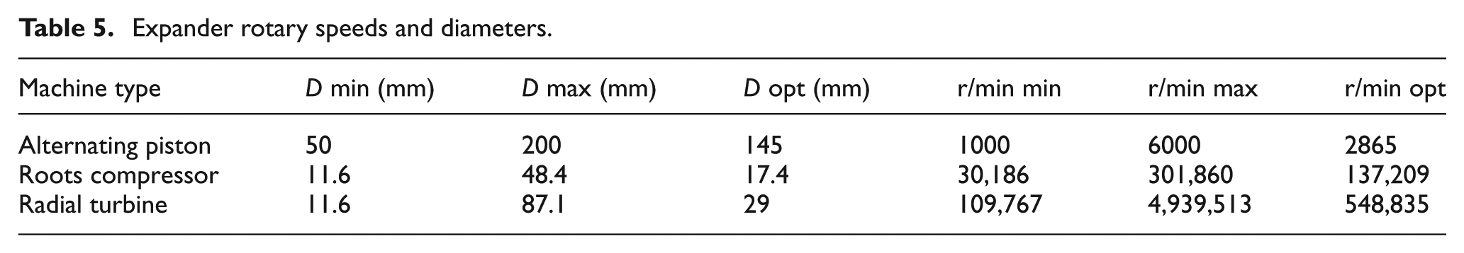
Again the situation is similar; roots and radial turbine have too high rotary speed while reciprocating piston is big but still possible to fit in the engine bay or below the vehicle. Rotary machinery offers smaller dimensions, but rotary speed is too high for the current technology. Alternating piston with isentropic efficiency of 80% is selected for expansion machine.
Non-ideal cycle
The recuperated power drops significantly with the drop in isentropic efficiency. Figure 9 represents the power as a function of pressure p2 and relation of gases for machine with 80% isentropic efficiency. This figure is obtained considering air to be ideal gas and calculating unknown values the same way as for ideal cycle. For the non-ideal cycle with
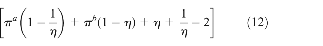
it can be concluded that for any π > 1 and 0 < η < 1, the value of parenthesis will be negative thereby with the rise in air mass flow the power will drop. From equation (9), it is clear that the optimal pressure drops as isentropic efficiency drops. There is an optimal pressure and mass flow that gives the maximum power that is around 3.5 bar and
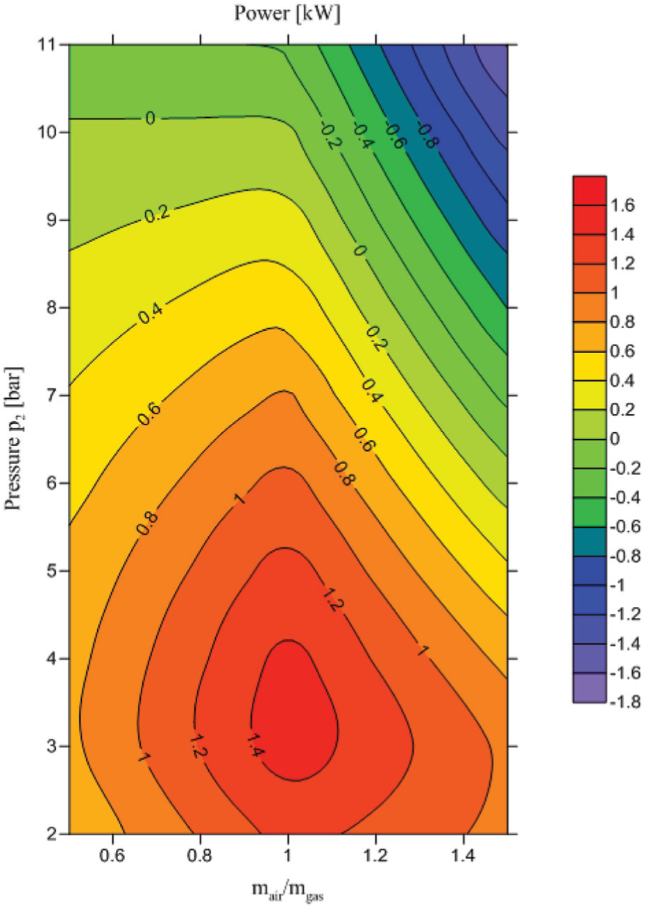
Recuperated power as a function of pressure at heat exchanger and relation of gases.
Like for the ideal cycle, for no-ideal cycle, the recuperated power for all NEDC points was also studied. Mass flow of air is set to be equal to mass flow of gas for each point, and the power as a function of pressure in the HE was analyzed. This is presented in Figure 10.

Power as a function of pressure in the heat exchanger for NEDC points.
For each engine point, the pressure that gives the maximum power was selected (crosses in Figure 10). The optimum pressure is lower than it was for ideal cycle, and out of the optimum pressure the recuperated power drops faster. Also, it can be seen that the maximum recuperated power for non-ideal cycle is less than for ideal, meaning that isentropic efficiency has a lot of influence on cycle efficiency. The exact amount can be seen in Table 6 for all NEDC points.
Recuperated power and engine efficiencies for ideal and non-ideal cycle.

Conclusion
Bottoming Brayton cycle for waste heat recuperation of a passenger automobile exhaust gasses was evaluated. Concrete 2-L turbocharged gasoline engine was used for the analysis and seven stationary points from the NEDC were considered as representative for various engine loads. First, the ideal cycle with isentropic compression and expansion was studied. It was concluded that for a fixed engine operative point, there is an optimal pressure in the HE that gives the maximum recuperated power. Also, for the ideal cycle, it was shown that for mass flow of air higher than mass flow of exhaust gas, the power does not depend on air mass flow. At these optimized points, the mass flow of air in the WHR system should be similar to the exhaust gas mass flow. The mass flow (for a point that gives the maximum power) and maximum geometrical limitations of machine size were inputs for compressor and expander machine selection. Analysis of Barber–Nichols NsDs diagram showed that the reciprocating piston is the most promising solution for concrete engine and selected operating point which was constant speed driving on a highway at 120 km/h. In the second part of the article, machines with realistic isentropic efficiency of 80% were estimated using the Barber–Nichols diagram. Like for the ideal cycle, it was shown that for non-ideal cycle there is also an optimal pressure that gives maximum power, but this pressure is lower than for ideal cycle. For non-ideal cycle, the power drops when mass flow of air is higher than mass flow of exhaust gas resulting that two mass flows should be similar for maximum power. For the concrete engine and selected NEDC points, the recuperated power and engine efficiency improvement were analyzed. For optimal pressure in the HE and mass flow relation, it was shown that power drops significantly with the drop in isentropic efficiency. The maximum recuperated power for non-ideal cycle was 1515 W at the point where reference engine power was 26,550 W. That improves the effective engine efficiency by 5.7% from 33.97% to 35.91%.
Footnotes
Appendix 1
Academic Editor: Jiin Y Jang
Declaration of conflicting interests
The authors declare that there is no conflict of interest.
Funding
This research received no specific grant from any funding agency in the public, commercial, or not-for-profit sectors.