
Abstract
Due to the flexibility of robot joints and links, industrial robots can hardly achieve the accuracy required to perform tasks when a payload is attached at their end-effectors. This article presents a new technique for identifying and compensating compliance errors in industrial robots. Within this technique, a comprehensive error model consisting of both geometric and compliance errors is established, where joint compliance is modeled as a piecewise linear function of joint torque to approximate the nonlinear relation between joint torque and torsional angle. A hybrid least-squares genetic algorithm–based algorithm is then developed to simultaneously identify the geometric parameters, joint compliance values, and the transition joint torques. These identified geometric and non-geometric parameters are then used to compensate geometric and joint compliance errors. Finally, the developed technique is applied to a 6 degree-of-freedom industrial serial robot (Hyundai HA006). Experimental results are presented that demonstrate the effectiveness of the identification and compensation techniques.
Keywords
Introduction
Robot manipulators play an important role in the industrial field. Industrial applications such as assembly, welding, and machining operations require highly accurate robot manipulators. However, present industrial robots have high repeatability but low accuracy. Therefore, robot manipulators need to be calibrated to meet the accuracy demands of industrial applications.
Error sources that affect the robot positioning accuracy can be divided into geometric errors and non-geometric errors. 1 Geometric errors may result from manufacturing imperfections, misalignments, and encoder offsets. Non-geometric errors may come from joint and link compliance, temperature variation, gear transmission error, and backlash in gear transmission. To the best of our knowledge, practical techniques to identify and compensate for all the geometric and non-geometric errors are not yet developed. For example, some research2–6 focused on identifying and compensating geometric errors related to the deviation of geometrical parameters with respect to their nominal values. However, for industrial robot manipulators, compliance errors related to the deflections of joints and links caused by gravity (payload and robot links) or applied forces contribute significantly to robot inaccuracy, in addition to geometric errors. Therefore, compensating compliance errors to further enhance robot positioning accuracy has been an active area of research.
The problem of modeling and identifying compliance errors has been studied in many publications. Some works have considered both joint and link flexibilities.7–9 However, as mentioned in Elatta et al., 1 Becquet, 10 and Gong et al., 11 compliance errors due to joint deflections are much more significant than those due to link deflections. Other research has focused on modeling and identifying joint compliance to compensate compliance errors due to joint deflections11–21 under the assumption that robot links are much stiffer than robot joints. For simplicity, robot joints in these works are mainly modeled as a linear torsional spring; joint deflections are the result of multiplication of constant joint compliance (inverse of joint stiffness) and joint torques. However, the experimental study in Kircanski et al. 22 reveals that the joint torque–torsion relation is nonlinear; joint torque can be expressed by a third-order polynomial function of joint deflections. Not much attention has been paid to identification and compensation of compliance errors related to nonlinear joint compliance. Jang et al. 23 divided the robot workspace into several local regions. In each local region, joint angular errors were modeled as the sum of geometric error and joint deflections, and then calibrated. A radial basis function network was then used to obtain the continuous error function of joint angular errors at any specified joint coordinate space. Similarly, Meggiolaro et al. 24 defined compliance errors (elastic errors) and geometric errors in a unified manner; they are approximated by a polynomial function of robot configurations and applied wrench. As these two methods used nonlinear error models, compliance errors related to nonlinear joint stiffness may be considered. However, these two methods require a large number of measurements in the calibration process, which is time consuming. In addition, the effect of geometric errors and compliance errors on the robot positioning accuracy cannot be individually observed in these two methods.
This article is devoted to identifying and compensating both geometric errors and compliance errors in industrial robots. To achieve this, a comprehensive error model is derived for combining geometric errors and compliance errors. In contrast to previous works, this error model takes into account the nonlinear relation between joint torque and joint deflection presented in Kircanski et al.
22
by modeling joint stiffness as a piecewise linear function of joint torque. For each joint of the robot manipulator, three non-geometric parameters must be identified in addition to geometric parameters: joint stiffness (denoted by
The remainder of this article is organized as follows. Sections “Modeling of kinematic error” and “Modeling of compliance error” describe the modeling of kinematic errors and compliance errors, respectively. Section “The proposed hybrid algorithm for robot calibration” presents the proposed hybrid algorithm for identifying these errors. Section “Experimental setup and measurements” describes the experiment design. Section “Experimental calibration results and validation” presents experimental calibration results for the Hyundai robot HA006. In addition, the calibration results are validated. The final section outlines some conclusions.
Modeling of kinematic error
The Denavit–Hartenberg (D-H) method
25
is used to model the kinematics of the Hyundai robot HA006, which allows one to model the robot joint with four parameters: joint angle (


A sketch of Hyundai robot HA006 and its attached link frames.
Nominal D-H parameters of Hyundai robot HA006.
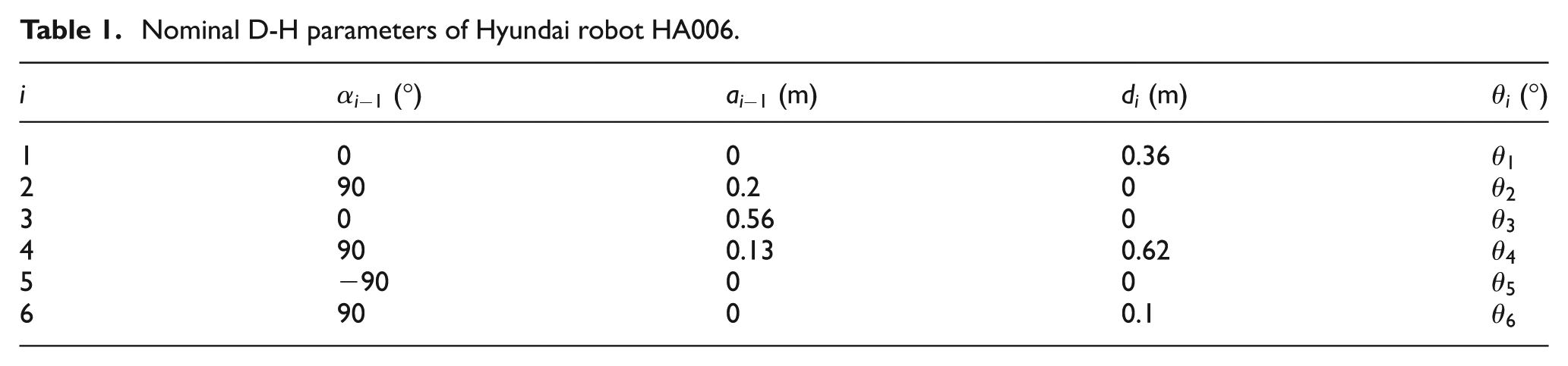
In the case of two consecutive parallel or near parallel joints (see joints 2 and 3 in Figure 1), small errors in the end-effector position cannot be modeled by small errors in the D-H link parameters because equation (1) is singular, so a small rotation of

Generally, the world fixed frame is defined arbitrarily by the user. Thus, the robot base frame

Since

where

where the vector
By successive multiplications of the transformation matrices, the position (

where
The resultant position errors of the end-effector (

where

where
There are 32 kinematic parameters in equation (6); however, some kinematic parameters are dependent on others:
Modeling of compliance error
This section first presents a new nonlinear joint stiffness model that allows us to take into account the nonlinear relation between joint torque and torsion. Based on this joint stiffness model, a mathematical formulation is then derived to describe the related compliance error.
Nonlinear joint stiffness modeling
The experimental study in Kircanski et al. 22 reveals that the behavior of the robot joint is nonlinear; the joint stiffness coefficient can be modeled as a second-order polynomial in joint torsion. Based on this nonlinear joint stiffness model, the torque–torsion relation is defined as 22

where
Simpler joint stiffness models of the robot correlate to easier identification of its stiffness parameters. We model the robot joint as a piecewise linear system to approximate its nonlinear behavior, which allows us to obtain a linear form of the identification equations that can be easily solved using a standard least-squares technique (see section “The proposed hybrid algorithm for robot calibration”). This linearization is conceptually explained in Figure 2. As the torque applied to the joint increases, the joint torsion increases at a diminishing rate. Accordingly, the joint stiffness as a function of applied torque can be approximated as


Conceptual drawing for linearization of the nonlinear torque–torsion relation.
where
Compliance error model
Assuming the robot’s links are much stiffer than its joints, compliance errors are due to the flexibility of robot joints under the link self-gravity and external payload. Effective torque in joint i is due not only to the gravity force related to link

where

where
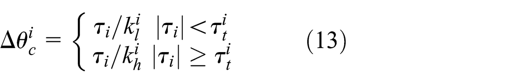
Based on the nonlinear joint stiffness model presented in section “Nonlinear Joint stiffness modeling,” the small joint deflection in joint
The Cartesian position errors of the robot end-effector due to the small joint deflections

where
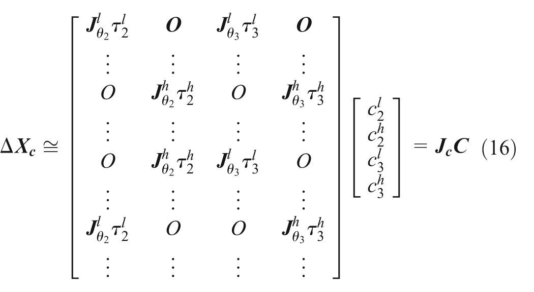
It is the fact that z-axes (the direction of joint rotation) of joints 2 and 3 lie within the gravity force flow and are coplanar with the gravity forces acting on the succeeding joint 4, 5, and 6 which leads to joints 2 and 3 suffering larger torques. Therefore, the compliance errors related to joints 2 and 3 are the most significant. From equations (13) to (14), the compliance errors due to the deflections in joints 2 and 3 can be modeled as

where
where
Similarly, equation (16) can be extended by including the compliance errors related to other joints. For example, if the compliance errors related to
The proposed hybrid algorithm for robot calibration
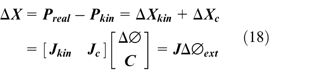
The real position vector (

where
where

where


Flowchart of the hybrid least-squares-GA-based algorithm: (a) GA and (b) iterative least-squares algorithm.
The values of joint angles describing the deflected equilibrium robot pose are given as follows

Thus, the matrices

Simultaneously, joint compliance parameters
Compute
Compute joint deflections
If
The resulting joint equilibrium position is updated as

After compensating for both kinematic errors and compliance errors, the residual position errors of the robot end-effector are given as follows

where

The overall iterative process (Figure 3(b)) terminates when
As mentioned before, the transition joint torques should be estimated. More precise estimation of the transition joint torques leads to better approximation of the nonlinear joint behavior, which results in a good modeling of the compliance errors. Consequently, the robot position accuracy is improved by compensating the compliance errors. Therefore, the performance of the transition torques estimation can be evaluated by the absolute position errors of the calibrated robot. Accordingly, GA is adopted to estimate the transition torques due to its advantages, such as exploring many regions of search space simultaneously, lowering sensitivity to local minima, and not requiring calculation of the derivatives. The flowchart of the basic GA is shown in Figure 3(a).
By combining GA and the least-squares algorithm, the defined kinematic parameters, joint compliance, and transition torques can be identified simultaneously. The principle of the proposed hybrid algorithm is shown in Figure 3 and can be described as follows:
Load data set, which in our case includes the nominal kinematic parameters, the masses of the load and links, the mass centers of links, and the measurement data consisting of the position vectors
Generate initial population pool; the individual is the transition joint torque vector
Compute the fitness value related to each individual based on the iterative least-squares algorithm, as shown in Figure 3(b). The fitness value is the absolute position error of the calibrated robot, that is,
Evaluate the fitness of each individual.
If the stopping criterion is satisfied, then stop. The outputs are the transition joint torque vector yielding the maximum fitness value and the simultaneously identified kinematic parameters and joint compliance values.
Generate new population by applying genetic operators, selection, crossover, and mutation based on the fitness values from step 4.
Repeat steps 3–6 until the stopping criterion is satisfied.
Experimental setup and measurements
As shown in Figure 4, the experimental setup composes of a robot, a laser tracker, and a reflector. The robot manipulator is a 6-dof serial robot (Hyundai HA006 with repeatability ±0.05 mm), and a payload of 6 kg is attached on its end-effector, which is the maximum loading allowed. The laser tracker (Laser Tracker LTD800 with accuracy of ±5 μm/m) and reflector are arbitrarily located near the robot base and attached on the payload, respectively.
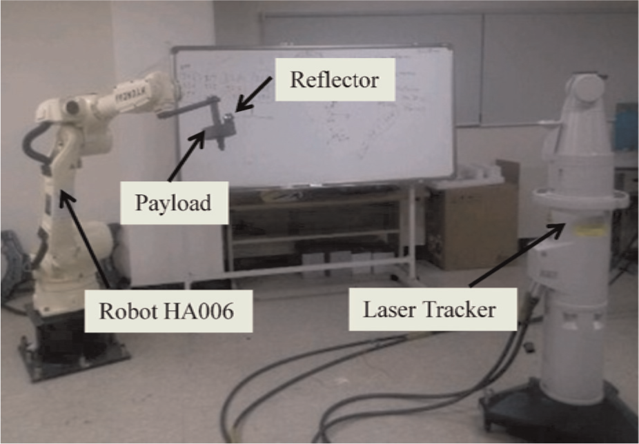
Experimental setup.
The positions of the robot end-effector were measured over 90 robot configurations evenly distributed within the reachable workspace. Due to the limitation of the measurement volume of the laser tracker, the reachable workspace where data acquisition was carried out is a sub-workspace of the entire workspace. As mentioned before, more precise estimation of the transition joint torques leads to better approximation of the nonlinear joint behavior. Thus, the effective torques in each joint computed at the measurement configurations used for calibration should be a diverse group with a large range. The computed torques over 90 measurement configurations in joint 2 are more diverse and have a wider range than those in joint 3 (see Figure 5). Accordingly, the 90 measurement configurations were arranged based on sorting their relevant torques in joint 2 in ascending order. Every other pose within the arranged 90 measurement poses is then selected. The resultant 45 poses (denoted by

Computed torques in joints 2 and 3.
Experimental calibration results and validation
This section presents the calibration results obtained by the proposed hybrid calibration algorithm. In addition, to validate the calibration results, the positions of the end-effector predicted by the calibrated robot over the arbitrary robot configurations (not used in calibration) are compared with the measured positions. Moreover, to show the benefits of compensating the joint compliance errors, the results of both calibration and validation are compared with those obtained by the conventional kinematic calibration.
Experimental calibration results
The measurements related to the pose set

Residual position errors over pose set
Second, in order to show the benefits of the calibration dealing with both kinematic and compliance errors, the conventional kinematic calibration was carried out to identify 27 kinematic parameters, that is, equation (7) is solved by the least-squares approach, with the pseudo-inverse that is similar to equation (19). This operation is applied iteratively until convergence. Figure 6 shows the residual position errors over the pose set
Third, the proposed calibration algorithm was used to calibrate the Hyundai robot HA006. We employed Optimization Tool Box (MATLAB R2008a) as the implementation of GA. As shown in Figure 5, the range of
Identified D-H parameters of Hyundai robot HA006 (–: undefined; x: unselected).

Identified transition joint torques and joint stiffness.


Residual position errors over pose set
Experimental validation
In the robot calibration experiment, the mean of the end-effector position errors over the arbitrary configurations (not used in robot calibration) indicates how accurately the calibrated robot manipulator will perform. Thus, to validate the calibration accuracy obtained by the proposed calibration algorithm, the calibrated robot was used to predict the positions of the end-effector over the pose set

Computed joint deflections over pose set

Residual position errors over pose set
The proposed calibration algorithm allows one to observe the effects of kinematic errors and compliance errors on the robot position accuracy individually. The positions of the end-effector after only compensating kinematic parameters can be computed based on the forward kinematics with the identified kinematic parameters (Table 2) and the joint angles

Residual position errors over pose set
Figure 11 shows robot position accuracy obtained by the conventional kinematic calibration, and the comparison with that obtained by the proposed calibration algorithm. The position accuracy of the robot calibrated by the conventional kinematic calibration is 0.156 mm with standard deviation of 0.078 mm; the maximum position error is 0.421 mm. The effect of compliance errors on robot position accuracy is not as clear in Figure 11 as in Figure 10 because the unmodeled errors (e.g. compliance errors) are propagated to the calibration results, that is, the kinematic parameters identified by the conventional kinematic calibration absorb these errors. Position accuracy of the robot calibrated using the proposed algorithm was improved with a rate of 41.67% compared to that obtained using the conventional kinematic calibration.

Comparison of position accuracy using conventional kinematic calibration and using the proposed calibration algorithm.
Conclusion
This article presents a practical technique for enhancing robot position accuracy by compensating both kinematic errors and compliance errors in industrial serial robots. In contrast to previous works, the robot joint is modeled as a piecewise linear system to approximate its nonlinear behavior. Based on this new joint stiffness model, a compliance error model is established. A hybrid least-squares-GA-based algorithm is then developed that allows one to simultaneously identify the defined geometrical and non-geometrical parameters through a comprehensive error model consisting of kinematic and compliance errors. In addition, to increase identification accuracy, measurement data used in robot calibration are selected properly. Finally, the advantages of the developed techniques are illustrated by experimental study of the Hyundai industrial 6-dof serial robot. The results show that the position accuracy of the robot after compensating for both kinematic and compliance errors is significantly improved at a rate of 98%. This represents an improvement of more than 41% in robot position accuracy obtained by the proposed calibration algorithm compared with the conventional kinematic calibration.
Footnotes
Academic Editor: Yangmin Li
Declaration of conflicting interests
The authors declare that there is no conflict of interests regarding the publication of this article.
Funding
This work was supported by the Ministry of Knowledge Economy both under the Human Resources Development Program for Convergence Robot specialists and under the Robot Industry Core Technology Project.