
Abstract
The hysteresis, stick–slip, and rotational speed-dependent characteristics in a basic dual mass flywheel are obtained from a static and a dynamic experiments. Based on the experimental results, a nonlinear model of the transferred torque in this dual mass flywheel is developed, with the overlying form of nonlinear elastic torque and frictional torque. The nonlinearities of stiffness are investigated, deriving a nonlinear model to describe the rotational speed-dependent stiffness. In addition, Bouc–Wen model is used to model the hysteretic frictional torque. Thus, the nonlinear 2-degree-of-freedom system of this dual mass flywheel is set up. Then, the Levenberg–Marquardt method is adopted for the parameter estimation of the frictional torque. Finally, taking the nonlinear stiffness in this model into account, the parameters of Bouc–Wen model are estimated based on the dynamic test data.
Keywords
Introduction
The reciprocating internal combustion engines are used in almost every automotive vehicle recently. The oscillated gas-pressure torque caused by the periodic combustion processes and the unbalanced inertia torque excites the driveline, which generates the torsional vibrations. Torsional vibrations in automotive vehicle bring a number of comfort problems, namely, “rattle noise.” Torsional vibrations transmitted from engines can be mechanically isolated when a dual mass flywheel (DMF) is fitted between the engine and transmission. 1
A basic DMF consists of two separated flywheels connected by a spring-damping damper, as shown in Figure 1. The long-travel arc springs are compressed or decompressed along the shell, transferring the torque from engine. To reduce wear, lubricating grease is filled in spring channel, generating damping as well. A applicable model of DMF is significant to predict the dynamic behaviors of power train. Walter et al.2–4 and Lei et al. 5 have simplified a DMF as a 2-degree-of-freedom system, which is a linear mass–spring–damper model. Using this model, the torsional vibration characteristics of the power train fitted with the DMF are predicted. However, Schnurr 6 has observed nonlinear dynamical phenomenon as early as 1990. A dynamic test for a super-long-travel DMF was conducted, and frictional hysteresis as well as the rotational speed-dependent characteristic was found. Before long-travel DMF, Albers 7 established a static mechanic model for a long-arc spring with a DMF, considering the friction in 1994, and investigated the hysteresis phenomenon under static condition. In 2009, Schaper et al. 8 also represented the nonlinear characteristics of an arc spring DMF and observed the friction behavior. Although the nonlinear characteristic has been observed, the practicable model for basic DMF has not been achieved yet.

Schematic diagram of basic dual mass flywheel (DMF).
Since the DMF cannot be primitively explained by the linear dynamical model, a nonlinear model that can predict the nonlinear characteristics of DMF needs to be developed. Therefore, this work develops a nonlinear model for a typical arc spring DMF, based on the static and dynamic experiments.
Nonlinear phenomenon
In this section, a static and a dynamic experiments of an arc spring DMF are represented. The torque from engine may take the form as

where
Figure 2 shows the experimental setup for the DMF. The DMF is excited by a converter motor, which is controlled by a specified transducer. The harmonic excitation frequency is equal to the base frequency, that is,

Experimental setup.

Torque–angle curves from static experiment.

Torque–angle curves from dynamic experiment.
Hysteresis phenomenon is observed in both static and dynamic experiments. The area enclosed by a complete loop denotes the energy dissipated. The curves in Figures 3 and 4 show that the areas enclosed change as the rotational speed changes, increasing with the increase in the rotational speed. Figure 3 also shows that the stick–slip phenomenon occurs. The arc springs stick again to the shell until the external torque is large enough to overcome the static friction. What is more, the stiffness increases with the increase in the rotational speed in loading processes. Furthermore, in Figure 4, the leans of the curves become steeper as the rotational speed increases, indicating that the stiffness enlarges with the increase in rotational speed. Thus, it is observed that the torque transferred by the DMF is rotational speed dependent.
Modeling the DMF
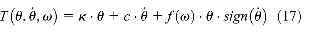
The DMF can be modeled as a 2-degree-of-freedom system, but the stiffness and the damping are no longer linear, according to the observation. The moments of inertia of the primary and secondary flywheels can be demonstrably solved as constant. While the transferred torque from the arc springs needs to be accurately analyzed, due to the observed nonlinear phenomenon. Thus, we can consider that the transferred torque consists of two nonlinear parts from spring torque and the friction, which may be described as

where
Nonlinearity of the stiffness
In this section, the forces acting on the arc spring are observed. The discrete method is used, which means that the whole arc spring is dispersed to spring coils. When using this method, three assumptions listed below should be followed:
Each spring coil is linear, referring to the linear spring design method;
Directions of each coil deformation are consistent, which are circumferential;
The friction force between the spring and spring holder is uniform.
The whole arc spring was dispersed to
In Figure 5,

Free-body diagram of coil i.
The shells in the circumferential spring dual mass flywheel (DMF-CS) guide the circumferential movement of the arc springs and then the friction will act on the contacting surfaces. Lubricating grease is filled in spring channel, reducing wear of the arc springs and generating damping. The lubricating stage determines the status of friction of two contacting surfaces. 9 Only the relative velocity of the contacting surfaces is high enough can they separate totally and hydrodynamic lubrication form, according to the Stribeck lubricating curve. 10 As is non-Newton fluid, the rheology of the lubricating grease characterizes nonlinearity. Under dynamic condition, the relative velocity is the torsional vibration speed. Because the friction damping consumes the energy, the vibration amplitude will be weakened. Therefore, the springs and slide may be difficult to be completely separated, and the hydrodynamic oil film cannot be fully formed. Under static condition, the relative velocity is lower. Therefore, the friction can be taken as dry friction.
Since the direction of the dry friction force is always opposite to the direction of the spring coil movement, the static mechanic model of the spring coil can be derived as follows
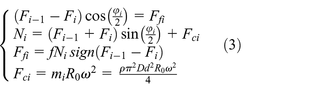
where
According to the first assumption, the elasticity of the spring coil is linear. Assume that the linear stiffness of the spring coil is
According to the linear spring theory,
11
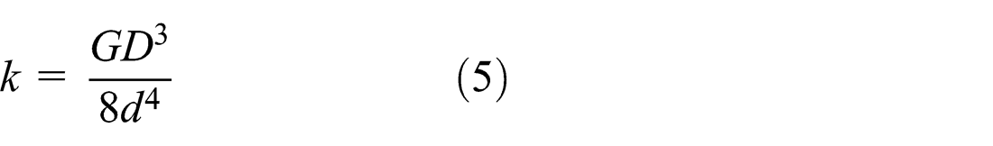
where
Assume that
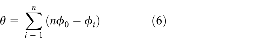
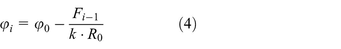
From equations (4) and (6),

The recurrence formula of elastic forces of the spring coils can be derived from equation (3). However, when the external torque is too small to overcome the friction force, the spring coil stays stick. Hence, the static friction should be taken into account. In this case, the static mechanic model of the spring coil is shown as

where

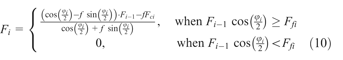
Combining equation (8) with equation (9), under the loading condition, the elastic forces transferred between spring coils can be derived as
In decompression process, the initial status of the arc spring is just the final status of the arc spring under the loading process. Thus, both
where

Therefore, under the decompression process, the elastic forces transferring between the spring coils can be summarized as

where
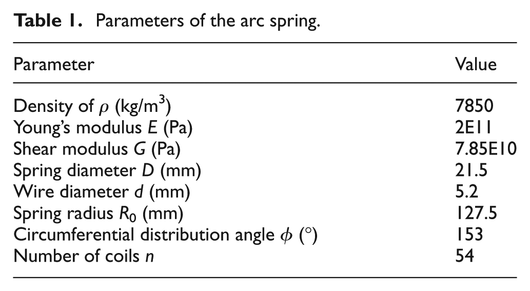
The parameters of the arc spring of this DMF are given in Table 1. Based on the above derivation, the relation of torque, angle, and rotational speed is simulated in Figure 6. The result shows that the transferring torque is approximately linear to the torsional angle but is nonlinear to the rotational speed. Obviously, the rotational speed-dependent torque results from the friction. The friction is taken as coulomb friction in the simulation, which is induced by the normal force. Moreover, the centrifugal force and the redirection force compose the normal force. The transferring torque can be expressed as the form of the combination of the friction torque with the linear elastic torque. For practical condition, the friction torque is regarded as the mixed friction torque consisted of viscous friction torque and coulomb friction torque. Hence, the model of transferred torque in this case can be described as

Parameters of the arc spring.

Relation of torque, torsional angle, and rotational speed under loading process.
where
The variations of the normal force and the redirection force with the torsional angle


Variation of the normal forces.
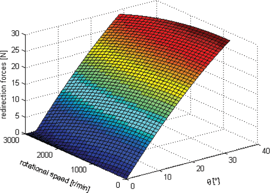
Variation of the redirection forces.
Thus, the coulomb frictional torque

In equation (16),
Consequently, the final mathematical model of the transferred torque at static condition can be rewritten as
The transferred torque series

Assume

where

where
and

Choosing appropriate values of
Estimated parameters at different rotational speeds.

Consider the mean value of parameters

Values of
Three nonlinear functions of


Curve fitting results of
Parameters of each function and the errors of curve fitting.

SSE: sum of squares; RMS: root mean square.
In Table 3, SSE, R2, and RMS represent the sum of squares due to error, the coefficient of determination, and the root mean squared error, respectively. The fitting results show that the third function describes the variation of
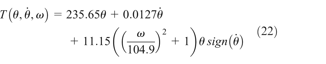
From equation (22), the transferred torque under 900, 1500, and 2100 r/min is plotted in Figure 11, which are compared with the static experimental results shown in section “Nonlinear phenomenon” as well. The results show that the established torque is available to describe the nonlinear transferred torque of the DMF.

Comparisons of torques from experimental results and equation (22): (a) 900, (b) 1500, and (c) 2100 r/min.
Since the amount of viscous damping coefficient is relatively small, the torque from the viscous damping is neglected. Therefore, the nonlinear stiffness of the DMF subjected to a static torque is shown as (Figure 12)

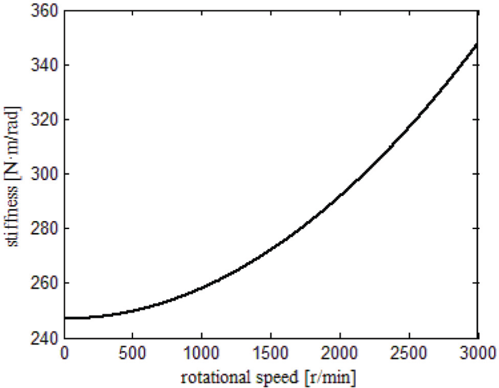
Variation of stiffness.
Nonlinearity of the frictional torque
The most widely used nonlinear hysteresis model is Bouc–Wen model. Bouc
13
first proposed the differential model to describe nonlinear hysteresis in 1967. Then, Wen
14
modified the model in 1976, which is Bouc–Wen model. The model can be used to predict various types of hysteretic behaviors. Adjusting the parameters of this model, we can obtain different shapes of the hysteresis. Here, the Bouc–Wen model has been employed to model the frictional torque. Therefore, the nonlinear 2-degree-of-freedom model can be described in Figure 13, where
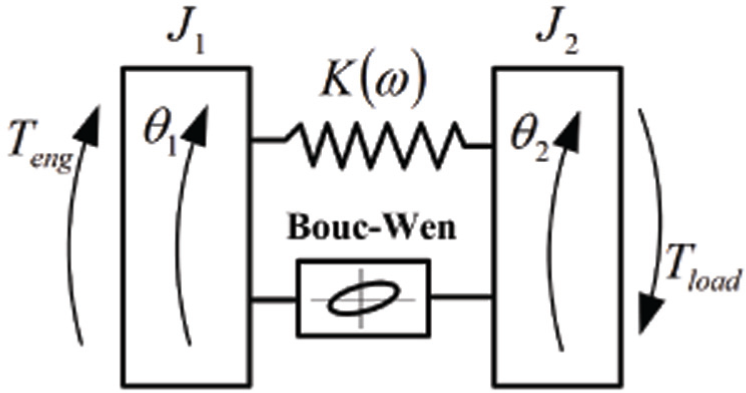
Nonlinear 2 degrees of freedom of the DMF.
The Bouc–Wen model takes the following form

where

where
Levenberg–Marquardt method15–17 is adopted to estimate the parameters. It has been proved that the Levenberg–Marquardt method is more robust and efficient than the widely used Gauss–Newton method. 18 The estimation scheme for the model parameters is divided to two steps:
Step 1. The exponential power n is given by a proper value at first. Moreover, the remaining parameters are estimated by the least square method.
The discrete torsional vibration and torque data can be obtained by the dynamic experiment, which are


Thus,
Step 2. Taking the parameters determined in step 1 as the initial iterative vector, the Levenberg–Marquardt algorithm is implemented. The dynamic experimental data shown in Figure 4 will be used to estimate the model parameters

where M is the number of selected j in step 1.
Estimated parameters.


Hysteretic curves by Bouc–Wen model: (a) 80 N m, 900 r/min; (b) 80 N m, 1500 r/min; (c) 80 N m, 2100 r/min; (d) 120 N m, 900 r/min; (e) 120 N m, 1500 r/min; and (f) 120 N m, 2100 r/min.
Conclusion
It is experimentally verified that the nonlinear hysteretic and rotational speed-dependent phenomenon exists in a long-arc spring DMF. Centrifugal force results in the rotational speed-dependent frictional force and then the nonlinear stiffness of this kind of the DMF. Considering the transferred torque as an overlying form of nonlinear elastic torque and the hysteretic frictional torque, a nonlinear 2-degree-of-freedom torsional vibration system for this DMF is presented in this work. The nonlinearity of stiffness and the hysteretic model of frictional torque are specifically investigated. A stiffness model of rotational speed is derived, according to the static mechanic model and the static experimental data. The Bouc–Wen model is adopted to model the hysteretic frictional torque. Incorporating the elastic torque and using the dynamic experimental data, the model parameters are estimated by Levenberg–Marquardt method. The estimated results show that the presented model can accurately describe the hysteretic characteristics.
Footnotes
Academic Editor: Ioan Pop
Declaration of conflicting interests
The authors declare that there is no conflict of interest.
Funding
This work was supported by National Natural Science Foundation of China under Grant 51405355.