
Abstract
To simplify the design process and improve the motor performance, a rotary ultrasonic motor with rotationally symmetrical structure has been designed, fabricated, and characterized. The stator consists of four connected sandwich-type transducers and eight driving feet. The rotor, a disk, and a disk-shaft are pressed on the two sides of the stator by a nut–spring system. To drive the rotor, two orthogonal longitudinal vibration modes of the stator should be excited. The operating principle of the rotary motor was analyzed by a mathematical model. By using finite element analysis, the feasibility of the operating principle was validated, and the optimal structure dimensions of stator were determined in order to improve the driving teeth motion. The overall dimensions of the prototype stator are 30 mm (width) × 30 mm (width) × 50 mm (length). Driven by alternating current signals with the driving frequency of 50.93 kHz and voltage 300 VP-P, the motor gave a maximal no-load speed of 157.9 r/min and a maximal output torque of 11.76 mN m.
Introduction
Ultrasonic motors (USMs) can be an attractive alternative to electromagnetic motors for their advantages, such as high torque at low speed, light weight, simple structure, large holding force without power supply, and no electromagnetic field induction.1–3 Piezoelectric ceramic is the common material which is used as drive elements. 4 The operation principle of piezoelectric USMs is to convert the electrical energy into mechanical oscillations of the stator based on the converse piezoelectric effect of piezoelectric ceramic and to drive a moveable body by the friction force between the stator and the moveable body. In recent years, USM has been applied in the fields of focusing system of camera, space explorations, ultra-precision measurement, medical equipment, and so on.5–8
USMs can be classified into traveling wave USM and standing wave USM. The well-known SHINSEI USR series is a typical example of bonded-type traveling wave USM, with the merits of simple structure and low cost in manufacture. 5 Then, the major researches of traveling wave USM were devoted to improve the motor performance and the efficiency of the motor. Generally speaking, the sandwich-type USM adopting d33 effect of piezoelectric ceramics can generate higher output power than bonded-type USM adopting d31 effect because the electromechanical coupling efficiency of d33 working mode is higher than d31. 9 Chen et al.10,11 proposed two kinds of thick ring stator with nested lead zirconium titanate (PZT) excitation. Two orthogonal out-of-plane or in-plane bending modes were excited to generate the traveling wave on the surface of the stator. Peng et al. 12 proposed another traveling wave USM with nested PZT, which is similar to the structure of Chen et al.'s motor, and provided an effective method to minimize the motor dimensions. But comparing with the bonded-type motor, the structure of stator with nested PZT is too complicated and difficult for manufacture. To simplify the structure of stator, there is a trend in many researches that one or more Langevin transducers are utilized to replace the bonded ceramics for the capability of generating higher output force. 13 Petit et al. 14 reported a “TWLIA” USM. The actual out-of-plane traveling wave of a pair of disk was induced by some evenly distributed longitudinal actuators. Liu et al. 15 used one sandwich-type transducer to excite the in-plane traveling wave of a cylinder stator. To obtain larger and balanced excitation force, four longitudinal vibration transducers were used in Liu et al.’s 16 another motor design. Lu et al. 17 proposed a dual stator-ring rotary USM. The traveling wave of the stator ring was excited by the first bending vibrations of four Langevin transducers. However, three common problems of the aforementioned sandwich-type rotary motors are seldom mentioned: first, the unbalanced distribution of transducers may cause inconsistent vibration amplitudes of different points of the stator surface. Second, the bending vibration frequency of the disk or cylinder must be close to the vibration frequency of the transducer in order to acquire higher output torque. The process of degeneration of the two modes is complicated and inconvenient in design process. Furthermore, the difference between the simulation results of the model and the test results of the prototype is common and hard to be avoided. And the deviation may also occur in manufacture and fabrication, which has adverse effect on the motor performance. Third, the disk or cylinder, as an extra transmission media of energy, must consume some energy to generate deformation in order to form the traveling wave. So, the efficiency is reduced. To overcome these problems, the characteristic of rotationally symmetrical structure can be utilized. Usually, a vibrator with rotationally symmetrical structure has some pairs of orthogonal modes. The frequencies of a pair of similar modes are very close. If the vibration modes are utilized to generate an elliptical motion of the driving foot, the process of mode degeneration can be simplified or even neglected.
In this article, a new rotary USM with optimized structure is proposed. The structure and principle of the motor are described in section “Structure and principle of the motor.” Then, the finite element method (FEM) analysis by software ANSYS10.0 for the motor is proposed in section “FEM analysis.” The experimental results of a prototype are introduced in section “Experiments.” The conclusion of this study is given in section “Conclusion.”
Structure and principle of the motor
Structure of the USM
Figure 1(a) shows the configuration of the stator. The overall dimensions of the prototype stator are 30 mm (B) × 30 mm (B) × 50 mm (L). A support plate is set in the middle of the stator for easy assembly and fixation. At each side of the support plate, there is a frame part that can be divided into four direct beams, four connecting beams, and four driving feet, as shown in Figure 1(b). The material of the frame parts is duralumin alloy (mass density ρ = 2800 kg/m3, Young’s modulus E = 7.2 × 10¹⁰ N/m2, Poisson’s ratio σ = 0.33).

Configuration of the motor: (a) structure of the stator, (b) structure of the frame part, and (c) structure of the motor.
One group of PZT ceramics and electrodes are sandwiched by one direct beam of Frame 1 and a corresponding direct beam of Frame 2. They are clamped by a screw, and the combination can be seemed as one Langevin transducer. Therefore, the stator is composed of four transducers, and they are connected by the connecting beams. To keep the orthogonality of the two operation modes and acquire consistent vibration amplitudes of the teeth at both sides of the stator, the directions of the screws in every two adjacent transducers are opposite, and the arrangement of transducers with same screw direction obeys the rotational symmetry with 180° around the longitudinal axis. Then, the four transducers are connected by the connecting beams. And the driving teeth on the connecting beams are designed to drive the rotor. As shown in Figure 1(c), the rotor is composed of a disk-shaft at one side of the stator and a disk at the other side, respectively. A spring and a nut are used to compress the rotor on the stator and adjust the pre-pressure.
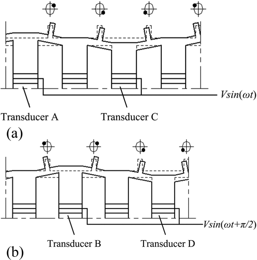
Figure 2 shows the arrangement of the four PZT element groups and electrodes. The PZT ceramics using the d33 effect are polarized in the thickness direction, and the polarized directions are signed as “+” and “−.” In addition, the support plate and frames must be grounded for voltage input.

Arrangement of the polarized ceramics and electrodes.
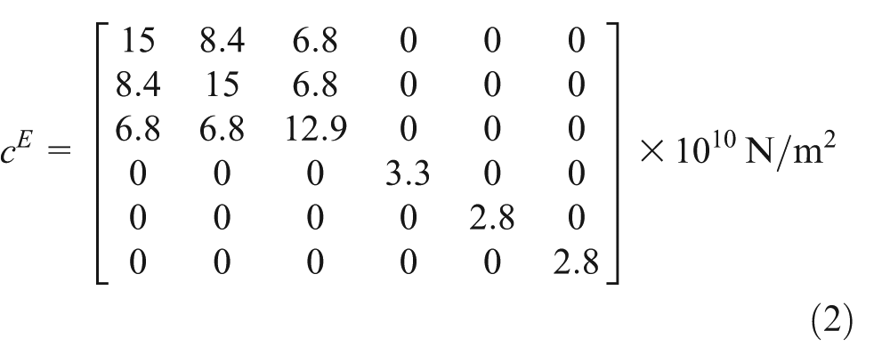
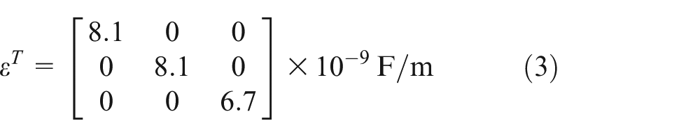
As the parameters of the PZT ceramics, PZT strain matrix d, structural stiffness matrix cE, and relative permittivity coefficient εT are expressed as

Operation principle
The operation principle of the proposed USM is that the longitudinal vibrations of the four transducers can be actuated by the PZT ceramics with applied alternating current (AC) voltage signals. Then, two orthogonal longitudinal vibration modes of the stator can be excited and degenerated by two voltage signals with a phase difference of π/2. The contraction and expansion of two adjacent transducers generate the displacements at the ends of the transducers in z-direction, and the displacements are transformed by the connect beams to drive the teeth swinging periodically. Then, the rotor is driven by the friction force between the teeth of the stator and the surfaces of two disks of rotor. As shown in Figure 1(c), the stator contains four transducers A, B, C, and D. The transducers A and C are excited by the sinusoidal voltage VA (VA = Vsinωt), where V and ω are the amplitude and angular frequency of input voltage, respectively. Because of the polarized directions of the PZT element groups A and C are opposite, group A should expand or contract in a direction contrary to group C. Then, the longitudinal vibrations of transducers A and C can be excited, and the deformation of the stator is shown in Figure 3(a) as mode A. Similarly, the longitudinal vibrations of the transducers B and D are excited by the sinusoidal voltage VB (VB = Vsin(ωt+π/2)), and the deformation of the stator is shown in Figure 3(b) as mode B.
Operation modes of the stator: (a) mode A and (b) mode B.
When the two modes are excited with the phase difference of π/2, the longitudinal displacements of the ends of any two adjacent beams can be expressed as u1 and u2

where A means the vibration amplitude at the end of the transducers.
As shown in Figure 4, the displacements in z- and x-directions of point PA on the tooth can be expressed as ξP, ςP


Displacements of point PA generated by the longitudinal vibration of two adjacent transducers.
where Ht means the height of the tooth and β means the deflection angle.
Because β is a minute angle, we could take sinβ = tanβ. The angle β can be expressed as

where LB means the length of the connecting beam.
And the oval trajectory movement equation of point PA can be expressed as

According to equation (7), a conclusion can be drawn that the vibration amplitude of point PA in x-direction should increase with the decrease in LB and the increase in Ht.
FEM analysis
A finite element model was initially used to confirm theoretical operation principle and find the proper driving frequencies of the orthogonal longitudinal vibration modes. In order to determine the optimal dimensions of the beam length (L), the tooth height (Ht), and the length of connecting beam (LB), the relationship between the dimensions and the elliptical motion displacement of teeth should be identified. The cross-sectional dimensions of the four longitudinal vibration transducers were fixed as 10 mm (C) × 10 mm (C) as shown in Figure 1(b). The optimal target of the actuator was to enlarge the vibration amplitude of all driving teeth. So, the model analysis of FEM was used to extract the vibration modes of stator. The simulated operation mode is shown in Figure 5, which is corresponding to Figure 4 in principle analysis. According to Figure 5, the thin connecting beams on which the teeth are located can enlarge the displacements of teeth, which should be beneficial to enhance the output torque.
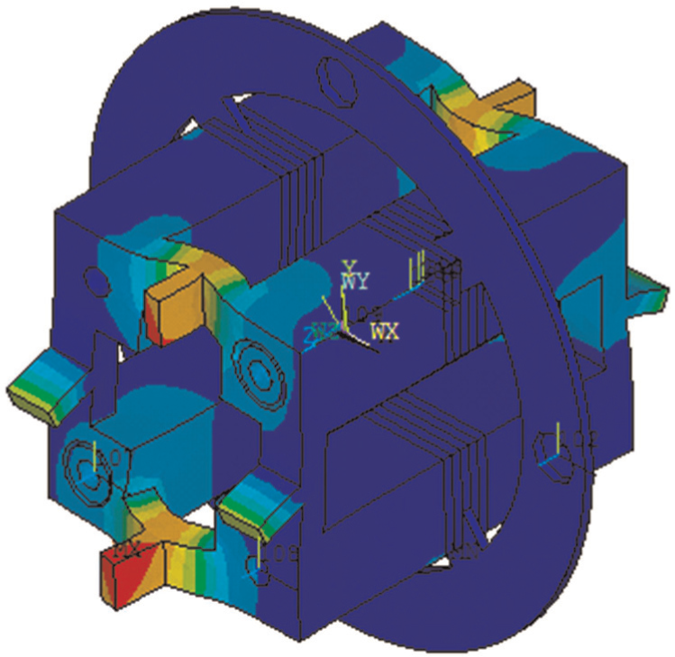
Operation mode shape of stator by FEM.
The transient analysis was accomplished to verify the formation of the teeth elliptical trajectories and identify the relationship between the dimensions of the stator and the vibration amplitude of teeth. Two sinusoidal voltage signals with a phase difference of π/2 were used to excite longitudinal vibration of the direct transducers. By changing the phase difference of the two exciting voltage signals, the rotary direction of the contact points on the stator can be altered.
Influence of the beam length on displacements of teeth in z-direction
According to the principle analysis, the elliptical motion of tooth is generated by the longitudinal vibration of two adjacent beams. Theoretically, the larger displacement of tooth means larger output torque. The maximum displacements of teeth in z-direction were simulated by changing the beam length (L). The thickness of the steel support plate was 1 mm.
Figure 6 shows the relationship between the beam length and the displacement of a tooth. The maximum displacement in z-direction occurs when L is between 37 and 42.5 mm. When L is larger than 42.5 mm, the displacement drops obviously. The reasons are that the frequency of interferential mode is too close to the working frequency, and the operation mode shape is changed severely. So, the optimal longitudinal dimension L can be considered as 40 mm by the graph.

Change in maximum displacement in z-direction of point PA depending on the beam length (L).
Influence of the tooth height on displacements of teeth in z-direction
To obtain larger vibration amplitude of the teeth, the tooth height (Ht) was changed during the simulation process, while the beam length (L) was fixed as 40 mm. As shown in Figures 1(a) and 4, point PA is on the surface of a tooth located on a connecting beam which is parallel with the x-axis. So, the displacements UX and UZ in x- and z-directions are necessary to generate an elliptical trajectory in x–z plane which can drive the rotor to rotate around the z-axis, and the displacement UY in y-direction is an undesired interferential factor which should be minimized. The displacement results of point PA are shown in Figure 7. When Ht increases from 1 to 4 mm, the displacement in x-direction UX increases from 0.8 to 4.3 μm, and it is consistent with the conclusion of equation (7). When Ht is larger than 4 mm, the displacement drops obviously. The reason is that the frequency of interferential mode is too close to the working frequency. The optimal tooth height should be 5 mm, because the displacements UX and UZ are close to each other and the displacement UY is relatively lower than the former two displacements.

Change in maximum displacement in z-direction of point PA depending on the tooth height (Ht).
Influence of the length of the connecting beam on displacements of teeth in x- and z-directions
The trajectories of point PA were simulated when LB was set as 5, 10, and 15 mm. The dimensions L and Ht were fixed as 40 and 5 mm, respectively. The projections of the three trajectories in x–z plane are shown in Figure 8. When LB is shortened from 15 to 5 mm, the maximum displacement of the trajectories in x-direction increases from 3.2 to 6.2 μm, and it is consistent with the conclusion drawn by equation (7). But the maximum displacement in z-direction occurs when LB is 10 mm, which means the enlargement effect of the thin connecting beams weakens when LB is too large or too small. So, the optimized dimension LB can be set as 10 mm.

FEM analysis results of the displacement of point PA.
As shown in Figure 1(b), the relationship between LB and B can be expressed as B = LB+ 2C, where C means the width of the direct beam. Because C is fixed as 10 mm, the optimized width of the motor is 30 mm.
Experiments
Figure 9 shows a photograph of a manufactured prototype of the proposed USM and the stator.
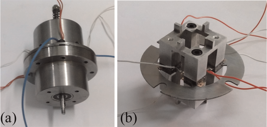
The prototype of proposed motor: (a) the motor and (b) the stator.
The vibration modes and the corresponding resonance frequencies of the prototype were measured by a scanning laser Doppler vibrometer (PSV-400-M2; Polytec, Germany). The end surface of the stator on which the teeth were located was taken as the test surface to gain the longitudinal vibration mode shapes and the vibration velocity average response spectrum. Figure 10 shows the test results. The deformed shapes are in agreement with the results of FEM modal analysis. The resonant frequencies of the two modes are 50.813 and 50.953 kHz, respectively. The results are about 1.9 kHz lower than the FEM mode analysis results. The major reasons of the discrepancy should be the manufacture error and the simplification of some detailed characters in the FEM model foundation, such as the screws and screw holes. However, thanks to the characteristic of rotationally symmetrical structure, the frequency difference between the two modes is only 0.14 kHz, and it is not necessary to consider mode degeneration.
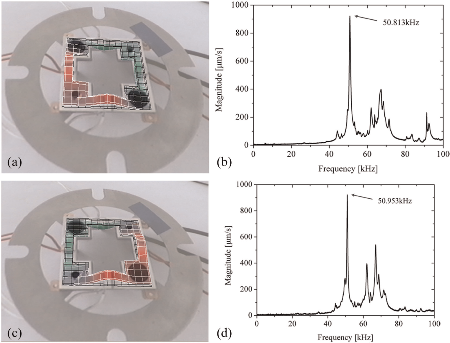
Vibration scanning results of stator: (a) vibration shape of mode A, (b) vibration velocity response spectrum under mode A excitation, (c) vibration shape of mode B, and (d) vibration velocity response spectrum under mode B excitation.
The speed and output torque can be affected by changing the driving voltage amplitude, driving voltage frequency, and phase difference between two-phase driving voltages. 18 For this prototype, as the simplest method, higher speed and torque can be obtained by improving the voltage. Figure 11 shows the output torque characteristics of the motor versus the speed with the exciting frequency of 50.93 kHz and excitation sinusoidal voltages of 200 and 300 VP-P.
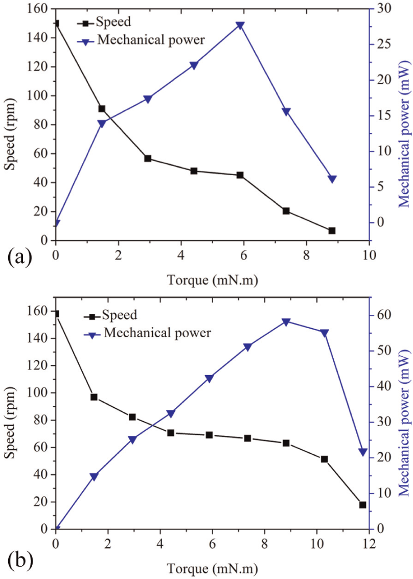
Mechanical output characteristics: (a) voltage 200 VP-P and (b) voltage 300 VP-P.
The typical speed–torque characteristics of USM are shown, which is high speed with low thrust force and low speed with high thrust force. The maximum no-load speed and maximum output torque of the prototype are tested to be 150 r/min and 8.8 mN m with 200 VP-P, and 157.9 r/min and 11.76 mN m with 300 VP-P. In Figure 11(a), the maximum mechanical power is 27.8 mW at the torque of 5.88 mN m. In Figure 11(b), the maximum mechanical power is 58.3 mW at the torque of 8.82 mN m. As shown in Figure 11(a) and (b), the no-load speed and maximum output torque increase 5.3% and 33.6%, respectively, when the applied voltage increases from 200 to 300 VP-P. Comparing with the output characteristics of the motor presented by Petit et al., 14 the proposed motor has more than 175% of maximum no-load speed, but the maximum output torque and output power are relatively lower. The major reason is that the volume percentage of PZT material in the prototype is too low. Therefore, the thickness of the PZT ceramics should be increased to improve the output characteristics and acquire larger torque. In fact, the contact condition of the teeth and the rotor is a crucial factor which affects the output characteristics of the motor directly. So, the parallelism of the two rotor disks should be ensured. And the height of the teeth should be consistent in order that all teeth can fully contact with the rotor disks and drive them well.
Conclusion
A novel rotary USM with rotationally symmetrical structure was proposed, designed, and tested. Four sandwich-type transducers are connected by thin beams as the stator, and two orthogonal longitudinal vibration modes can be actuated to generate elliptical trajectories of teeth and to drive the rotor. Comparing with other rotary USM excited by sandwich-type transducers, the common part of “disk” or “cylinder” is eliminated, and the motor is simpler in structure. The operation principle is analyzed by a simplified mathematical model. By using finite element analysis, the feasibility of the proposed motor was validated and the influences of the dimensions on the driving teeth motion were determined. According to the results of analysis, the motor has no frequency matching problem between two similar vibration modes with very close frequencies. So, the process of design and fabrication is more convenient. A manufactured prototype motor has been experimentally characterized and exhibited a maximal no-load speed of 157.9 r/min and a maximum output torque of 11.76 mN m, driven by AC signals with the driving frequency of 50.93 kHz and voltage 300 VP-P.
Future study will focus on the following aspects: adjusting the dimensions of the PZT ceramics to acquire larger deformation of the transducers and higher output torque of motor, testing different frictional materials to reduce the abrasion at the contact surface of the motor, and optimizing the structure for miniaturization.
Footnotes
Academic Editor: Seyed N Mahmoodi
Declaration of conflicting interests
The authors declare that there is no conflict of interest.
Funding
This research was financially supported by the National Natural Science Foundation of China (No. 51375107) and State Key Laboratory of Robotics and System (HIT No. SKLRS201408B).