
Abstract
In this article, a degradation assessment model has been proposed for electro-hydraulic shift valve in power-shift steering transmission. Our work is motivated by the failure mechanism of abrasive wear with a mathematic model. Abrasive wear will consecutively enlarge the clearance between the friction pairs. It is an overwhelming wear mechanism in the degradation of shift valve within serious contaminated fluid. Herein, a mathematic model is proposed by considering particle morphology and abrasion theory. Such model has been verified for its applicability and accuracy through comparison between the theoretical and experimental results.
Introduction
An electro-hydraulic shift valve, which is applied for switching hydraulic fluid paths through a displacement of spool relatively to grooves, controls the combination or separation of the wet shift clutch in power-shift steering transmission (PSST). 1 In consideration of the critical clearance space between valve body and spool, solid particles entrained in fluid can be the most crippling substances. 2 Such contaminant-entrained fluid will induce two kinds of failure modes for a valve: one is the contaminant lock, which will increase the spool motion force even to the point of seizure; another is the abrasive wear, which will gradually enlarge the flow of internal leakage fluid. 3 Such enlargement, shown as performance degradation of a valve, will obviously shorten its service lifetime.
The prediction, control, and prevention of particulate-related failures of hydraulic and lubricated machinery have become popular issues from the early 1970s. Since then, the abrasive (particulate) wearing characteristics are introduced into the promotion of performance and reliability. 4 There are three ways in which particulates contact with the mating surfaces of a valve: friction lock, plowing and cutting, and clogging and wedging. 5 However, most investigations have focused on the effects of friction lock as contaminant sensitivity in hydraulic valves.
Abrasive wear occurs when hard particles slide on a softer surface and damage the interface by plastic deformation or fracture. Solid particles that are sufficiently harder will potentially stick into the mating surfaces. 6 Thus, three-body abrasion, one of abrasive wearing modes, will abrade either one or both of those surfaces. It is generally acknowledged that adhesion, one of the wear mechanisms, occurs at the initial wearing stage. 7 After abundant particles get trapped at the interface, three-body abrasive wear generates. Therefore, it is an overwhelming wear mechanism for friction pair within serious contaminated fluids. 8 Wherein shape, size, and material hardness of particles; particulate concentrations; and sliding velocity of the interface are the influencing factors for the intensity of three-body abrasive wear.
Failure analysis
An electro-hydraulic shift valve (Figure 1) is a cartridge valve combining a set of regular valves with an electromagnetic switching valve (as a pilot valve). The liquid under a certain pressure controlled by the pilot valve is applied to provide motion force for spool, which acts make-break switching to control the fluid flow. The particles that have one aspect exceeding the clearance space can become implanted into the wall surface—by lodging between asperities, wedging due to irregular particle shape or clearance space, and by the radial displacement of the spool due to hydraulic unbalance. 9
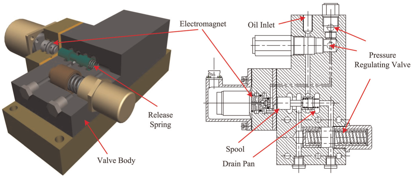
Electro-hydraulic shift valve.
Within a shift valve, direct contact between the mating surfaces has a much lower probability due to the lubricant capability and hydrodynamic effect of hydraulic fluid. Besides, there are large quantities of particles with different sizes suspended in the fluid as cumulative normal distribution. Hence, three-body abrasive wear will be induced by these solid particles trapped at the interface. The mating surfaces will generate plastic deformation due to those hard particles entrained in oils plowed or pitted on them. It is concluded that abrasive wear, especially a three-body wearing mode, causes consecutive enlargement of the internal leakage flow and then acts logically as a vital factor in performance degradation and lifetime shortening of a shift valve (Figure 2).

Internal leakage.
Material removal from the surfaces via abrasive deformation occurs by several deformation modes that include plowing, wedge formation, and cutting. 10 Plowing results in a series of grooves as a result of the plastic flow of the softer material. The plowing process also causes subsurface plastic deformation and may contribute to the nucleation of surfaces and subsurface cracks. Further loading and unloading (low-cycle, high stress fatigue) cause these cracks and pre-existing voids and cracks to propagate (in the case of subsurface cracks to propagate parallel to the surface at some depth) and join neighboring cracks which eventually shear to the surface leading to thin wear platelets. As a result, plowing process included in abrasion will gradually increase the roughness of the mating surfaces and thereby enlarge the clearance space for leaking more fluid.
According to the above analysis, when solid particles entrained in leakage fluid squeeze into the annular gap (Table 2), they will simultaneously damage the mating surfaces so as to increase the flow of internal leakage fluid. Such abrasive process will cause performance degradation ultimately up to a certain failure threshold. Therefore, in this article, a mathematic model of degradation assessment and life prediction will be proposed under contaminant circumstances. Besides, the effects of factors which will shorten a valve’s service lifetime will be tested and separately discussed for evaluating contaminant resistance capacity.
Morphology simplifications of particles
In contaminant oils, each particle either generated from any abrasion mechanism or derived from multifarious sources has a unique geometric form. If an identical description of particle morphology can be recommended to approximately represent all particle shapes in the proposed model, the modeling process of abrasive deformation can be simplified. In this section, a discrete Fourier transform (DFT) method is applied to analyze two-dimensional images of particles with the purpose of extracting morphological characteristics and therewith acquiring a consistent, proximate, and geometric description of the particles. 11
Particle morphologies
In previous tests, substantial samples of used oils have been accumulatively gathered from hydraulic and lubrication system in PSST as research objects. We diluted those oil samples and then passed them over the slides to produce ferrograms. By observing under a microscope, various particulate morphologies were acquired as images (Figure 3). Those images carried with the morphological information were instantly imported into Photoshop (PS) to draw out the particulate contours and then be exported as binary images (Figure 4).

Ferro-graphic images.

Processed binary images.
Simplification with DFT
By selecting the barycenter of particle contour as the pole of polar coordinate (Figure 5), any point from among the particulate contour can be represented as
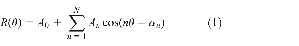
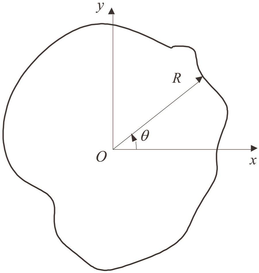
Polar coordinates.
Assuming that
Four kinds of geometric form were provided to approximate the shape of the particles (Figure 6). Each of them corresponds to a Fourier coefficient and a form-proportional coefficient
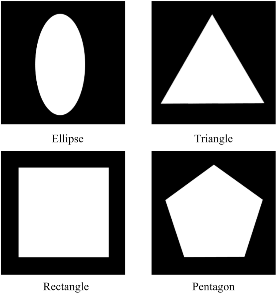
Geometric forms.
Corresponding relation.

In general, a particle contour is discretely constituted by a series of points in limited quantity. Therefore, DFT method has been applied for acquiring the binary images as follows

where
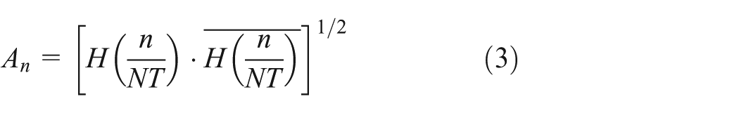
It is difficult to directly solve equation (3) because there are
Through programmed FFT in MATLAB, four kinds of form-proportional coefficients were acquired by processing the binary images of particles. We randomly selected 20 sets of data as examples and listed them in Table 2. Therein, the maximum coefficient
Form-proportional coefficient.
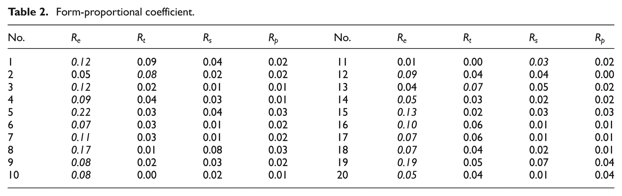
A total of 200 particles have been analyzed and thereby the frequencies and its percentage of all samples have been calculated (Figure 7). Wherein more than 87 per samples can be represented as ellipse (equal to spheroidicity in three dimensions). It is concluded that spheroidicity can approximately represent as a simplified shape of all particles and be used in the following model.

Percentage of
Degradation model
When solid particles entrained in fluid squeeze into the annular gap, they will simultaneously damage the mating surfaces. In consideration of plastic deformation, service life
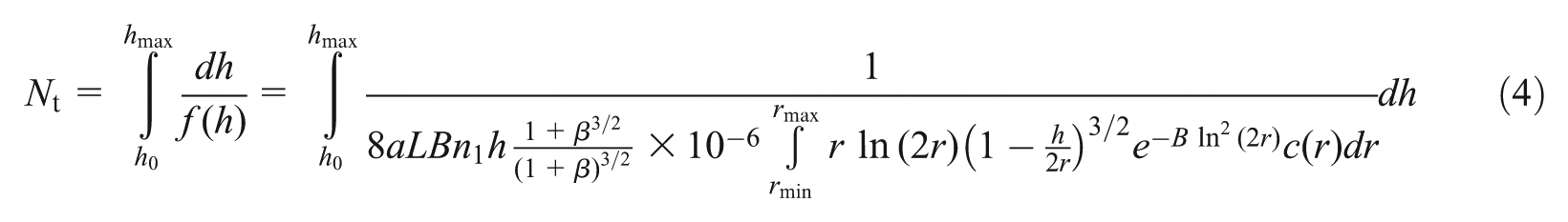
Substituting parameters (Table 3) into equation (4), the theoretical maximum motion times of the valve under abrasion are solved as

Parameters.

Experiment study
The mathematic model is proposed for the performance degradation and the life prediction of an electro-hydraulic shift valve. Through comparing the results of prediction to a test, the mathematic model will be examined for its applicability and accuracy. 14
An electro-hydraulic shift valve degrades in performance due to particle abrasive wear. The term “contaminant service life” denotes the degradation in performance of a component due to the presence of contaminant in the fluid. Three variables can be used to evaluate the level of contaminant wear. These are as follows: (1) the spool motion times, (2) downstream flow, and (3) the internal leakage flow. 15 These data gained from the test can be evaluated and a unique service life can be assigned to the valve.
Experimental methodology
A test facility is used, as illustrated in Figure 8. The test fluid temperature must be 65 °C (150 °F). An obconic oil tank ensures that particles will not deposit together at the bottom. The oil supply system needs an insensitive pump for contamination, like a gear pump. Meanwhile, the effect of particle fragmentation in gear pump is inconspicuous.

Test facility.
Install the valve in the test facility and attach suitable measurement equipment, as shown in Figure 9. Electro-hydraulic valve (cartridge valve) that operates the wet shifting clutch in PSST is the test object. It mainly consists of the spool, the pilot electromagnet valve, and the pressure regulating valve. The internal leakage rate will consecutively increase with the gap size enlargement due to the degradation of the mating surfaces’ abrasion. Hence, the leakage rate is the most applicable criteria for the evaluation of abrasive wear.

Tested valve.
The valve will be repetitively operated under the circumstance of contamination. Meanwhile, the trend of the leakage flow enlargement is observed and the interval value with the corresponding motion times is recorded. After test, a morphology comparison to verify the wear mechanism with the original spool’s surface is made.
The valve locates backward at the precise filter in the hydraulic circuit of PSST. Evidence shows that the dynamically balanced contamination level at the position of a valve located is 10 (NAS). Thus, how to simulate actual contaminant circumstance with selecting appropriate test dust has become a key problem. In recent years, with the development of contamination control research, the air cleaner fine test dust (ACFTD) is common in compounding contamination oils. 16 As shown in Figure 10, the morphologies of most ACFTD particles approximate spheroidicity. Moreover, the chemical compounds of particles are predominantly SiO2 and Al2O3.

Dust morphology.
Test procedure is as follows: (1) compound ACFTD particles with oils according to gain necessary contamination level and therewith inject the mixed contamination oil into the oil tank. (2) When the test pressure and flow rise up to a rated value, the tested valve is operated as reciprocating motion at a frequency of 20 times per minute. The data gained from this test can be evaluated and a unique leakage flow is assigned to the valve if desired.
Experimental results and validation
Internal leakage flow
The curve of internal leakage flow is presented as consecutive and slow enlargement, as shown in Figure 11. The thing to note here was that the data gained from the test are unilateral flow, which was half of the total leakage flow. At the very beginning, initial leakage flow was theoretically determined by the minimal clearance under structural constraint. The test stopped at the operating time of 170 h after the leakage flow had approached the maximum allowable value. During the time, there were 7.13e5 times of switching motions in all for the spool under a constraint of leakage flow.
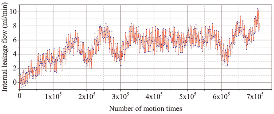
Test results.
Under a limitation of the maximum leakage flow, the theoretical life-cycle is compared with the test value, as shown in Table 4. Therein, the theoretical value is less than the test value for about 67,000 times, which are 10.4 per error.
Life-cycle comparison.

Worn-out morphology
At the end of the test, morphologies of the surface in the overhauled valve have been observed under scanning electron microscope (SEM). 17 The spool was selected as the observation object due to its smaller size. It can be seen that the morphologies of worn surfaces have greater differences than the initial (unworn) surfaces (Figure 12). This was because the particles, which were trapped at the interface, caused severe abrasion on the surface as the reciprocating motion of the spool. The vertical and regular patterns were the machine marks in circumferential direction (Figure 12(a)). After the test, there were only wear grooves that parallel the axis (Figure 12(b)). This was the mark that hard particles slide on the surfaces in valves. Moreover, a series of grooves were the plastic flow of the material as a result of plowing. After the surface has been plowed for several times, material removal occurred by a low-cycle fatigue mechanism, which is the primary material removal mode.

Spool surface (100×). (a) Before worned and (b) after worned. X axis represents as axial direction; Y axis represents as radial direction.
A high-power image clearly showed the width of several grooves under plowing (Figure 13). The width (<10 µm) generally equaled to the diameter of implanting area which was less than a particle diameter. Moreover, besides the plowing grooves, there were several shorter scratches or “pits” that are generated by the rolling action of particles.

Spool surface (1000×) (a) Before worned and (b) after worned. X axis represents as axial direction; Y axis represents as radial direction.
In conclusion, there are two kinds of morphologies in abrasive wear. One is the groove that is generated by plowing; another is the pit that is generated by rolling. The proportion of plowing or rolling relates to the hardness ratio of the material between the particles to spool. That is, when the hardness of the particle is greater than the spool, the proportion of plowing will increase (and vice versa).
Result analysis
Solid contaminants will silt in the clearance space. These contaminants, especially particles, make a direct contact with the mating surfaces. 18 Meanwhile, several particles implant into the surfaces with a rotatable motion. As a result, abrasive wear that generates at the mating surfaces will enlarge the clearance space consecutively with the same to leakage flow. There are three characteristics concluded for abrasive wear:
When a severe pressure is forced on a particle, it will crack into debris eventually under a pressure value that exceeds the ultimate strength of the material. Therefore, in the region less than the ultimate strength, the effect of abrasive wear shows as a series of discrete pit on the mating surfaces.
In general, the particles implant and act together with a lower hardness surface, the valve body. After an adequate reciprocating motion times of a spool, the wear grooves or furrows that parallel the axis are distributed uniformly on frictional surfaces.
In most cases, the effects of abrasive wear for the mating surfaces are only performed as the plastic and elastic deformation, not the micro-cutting wearing mechanism. Therefore, the fatigue wear induced by the multiple plowing is the primary material removal mode.
Conclusion
Solid particles entrained in fluid abrasively damaged the mating surfaces so as to increase the internal leakage flow and eventually induce the performance degradation up to a certain failure threshold. In this article, DFT method has been applied for acquiring a consistent description of different particle morphologies in the proposed model. In consideration of plastic deformation and abrasive wearing process, we proposed a degradation model adapted for life prediction of shift valve. Meanwhile, numerical solution methods were applied for solving. And then, a test facility has been established to evaluate the leakage flow variation and service lifetime.
From the results, the following conclusions are obtained:
More than 87 per particles in PSST can be described as ellipse which is equivalent to spheroidicity approximately in three-dimensional space.
There are two kinds of wear morphology in particulate abrasion. One is the groove, which is generated by plowing; another is the pit, which is generated by rolling. In most cases, the effects of particulate wear are only performed as plastic and elastic deformation, not the micro-cutting wearing mechanism.
Footnotes
Academic Editor: Francesco Massi
Declaration of conflicting interests
The authors declare that there is no conflict of interest.
Funding
This study was supported by the Advanced Program (40402010104) and the Innovation Program (VTDP-3503) and also by National Natural Science Foundation of China (Grant No. 51475044).